- About this Guide
- Chapter 1, Install Shelf and Common Control Cards
- Chapter 2, Connect the PC and Log into GUI
- Chapter 3, Turn Up a Node
- Chapter 4, Perform Node Acceptance Tests
- Chapter 5, Provision Transponder and Muxponder Cards
- Chapter 6, Turn Up a Network
- Chapter 7, Create Channels and Circuits
- Chapter 8, Manage Alarms
- Chapter 9, Monitor Performance
- Chapter 10, Manage the Node
- Chapter 11, Provision DWDM Cards
- Chapter 12, Add and Remove Cards and Nodes
- Chapter 13, Maintain a Node
- Chapter 14, Power Down a Node
- Chapter 15, Shelf Hardware Reference
- Chapter 16, Card Reference
- Chapter 17, Node Reference
- Chapter 18, Network Reference
- Chapter 19, CTC Operation Reference
- Chapter 20, Security Reference
- Chapter 21, Timing Reference
- Chapter 22, Management Connectivity Reference
- Chapter 23, Alarm Management Reference
- Appendix A, CTC Information and Shortcuts
- Appendix B, Hardware Specifications
- Appendix C, DWDM Administrative and Service States
- Appendix D, Network Element Defaults
- Before You Begin
- NTP-G128 Manage Pluggable Port Modules
- NTP-G33 Create a Y-Cable Protection Group
- NTP-G96 Modify Line Settings and PM Parameter Thresholds for TXP_MR_10G and TXP_MR_10E Cards
- DLP-G216 Change Card Settings for TXP_MR_10G and TXP_MR_10E Cards
- DLP-G217 Change Line Settings for TXP_MR_10G and TXP_MR_10E Cards
- DLP-G218 Change Section Trace Settings for the TXP_MR_10G and TXP_MR_10E Cards
- DLP-G219 Change the TXP_MR_10G or TXP_MR_10E Card Line Thresholds for SONET or SDH Payloads
- DLP-G319 Change the TXP_MR_10G or TXP_MR_10E Card Line Thresholds for 10G Ethernet LAN Phy
- DLP-G301 Provision the TXP_MR_10G and TXP_MR_10E Trunk Port Alarm and TCA Thresholds
- DLP-G302 Provision the TXP_MR_10G and TXP_MR_10E Client Port Alarm and TCA Thresholds
- DLP-G221 Change OTN Settings for TXP_MR_10G and TXP_MR_10E Cards
- NTP-G97 Modify Line Settings and PM Parameter Thresholds for MXP_2.5G_10G and MXP_2.5G_10E Cards
- DLP-G222 Change Card Settings for MXP_2.5G_10G and MXP_2.5G_10E Cards
- DLP-G223 Change Line Settings for MXP_2.5G_10G and MXP_2.5G_10E Cards
- DLP-G224 Change Section Trace Settings for MXP_2.5G_10G and MXP_2.5G_10E Cards
- DLP-G225 Change Trunk Settings for MXP_2.5G_10G and MXP_2.5G_10E Cards
- DLP-G226 Change Line Thresholds Settings for MXP_2.5G_10G and MXP_2.5G_10E Cards
- DLP-G303 Provision the MXP_2.5G_10G and MXP_2.5G_10E Trunk Port Alarm and TCA Thresholds
- DLP-G304 Provision the MXP_2.5G_10G and MXP_2.5G_10E Client Port Alarm and TCA Thresholds
- DLP-G228 Change Line OTN Settings for MXP_2.5G_10G and MXP_2.5G_10E Cards
- NTP-G98 Modify Line Settings and PM Parameter Thresholds for TXP_MR_2.5G and TXPP_MR_2.5G Cards
- DLP-G229 Change Card Settings for TXP_MR_2.5G and TXPP_MR_2.5G Cards
- DLP-G230 Change Line Settings for TXP_MR_2.5G and TXPP_MR_2.5G Cards
- DLP-G231 Change Section Trace Settings for TXP_MR_2.5G and TXPP_MR_2.5G Cards
- DLP-G232 Change TXP_MR_2.5G and TXPP_MR_2.5G Cards Line Threshold Settings for SONET or SDH Payloads
- DLP-G320 Change the TXP_MR_2.5G or TXPP_MR_2.5G Card Line Thresholds for 1G Ethernet or 1G FC/FICON Payloads
- DLP-G305 Provision the TXP_MR_2.5G and TXPP_MR_2.5G Trunk Port Alarm and TCA Thresholds
- DLP-G306 Provision the TXP_MR_2.5G and TXPP_MR_2.5G Cards Client Port Alarm and TCA Thresholds
- DLP-G234 Change OTN Settings for TXP_MR_2.5G and TXPP_MR_2.5G Cards
- NTP-G99 Modify Line Settings and PM Parameter Thresholds for MXP_MR_2.5G and MXPP_MR_2.5G Cards
- DLP-G235 Change Card Settings for MXP_MR_2.5G and MXPP_MR_2.5G Cards
- DLP-G236 Change Client Line Settings for MXP_MR_2.5G and MXPP_MR_2.5G Cards
- DLP-G237 Change Distance Extension Settings for MXP_MR_2.5G and MXPP_MR_2.5G Cards
- DLP-G238 Change OC-48/STM-16 Settings for MXP_MR_2.5G and MXPP_MR_2.5G Cards
- DLP-G239 Change Section Trace Settings for MXP_MR_2.5G and MXPP_MR_2.5G Cards
- DLP-G240 Change MXP_MR_2.5G and MXPP_MR_2.5G Card Line Threshold Settings for SONET or SDH Payloads
- DLP-G321 Change the MXP_MR_2.5G or MXPP_MR_2.5G Card Line Thresholds for 1G Ethernet or 1G FC/FICON Payloads
- DLP-G307 Provision the MXP_MR_2.5G and MXPP_MR_2.5G Trunk Port Alarm and TCA Thresholds
- DLP-G308 Provision the MXP_MR_2.5G and MXPP_MR_2.5G Client Port Alarm and TCA Thresholds
Provision Transponder and Muxponder Cards
This chapter explains how to provision transponder (TXP) and muxponder (MXP) cards. The provisioning must be performed before you provision the dense wavelength division multiplexing (DWDM) network and create circuits.

Note ![]() Unless otherwise specified, "ONS 15454" refers to both ANSI and ETSI shelf assemblies.
Unless otherwise specified, "ONS 15454" refers to both ANSI and ETSI shelf assemblies.
Before You Begin
Before performing any of the following procedures, investigate all alarms and clear any trouble conditions. Refer to the Cisco ONS 15454 Troubleshooting Guide or the Cisco ONS 15454 SDH Troubleshooting Guide as necessary.

This section lists the chapter procedures (NTPs). Turn to a procedure for applicable tasks (DLPs).
1. ![]() G128 Manage Pluggable Port Modules—Complete this procedure to provision a multirate pluggable port module (PPM), provision or change the optical line rate of a PPM, or delete a PPM. PPMs provide the fiber interface to the TXP and MXP cards. With the exception of the TXP_MR_10G card, all TXPs and MXP accept PPMs.
G128 Manage Pluggable Port Modules—Complete this procedure to provision a multirate pluggable port module (PPM), provision or change the optical line rate of a PPM, or delete a PPM. PPMs provide the fiber interface to the TXP and MXP cards. With the exception of the TXP_MR_10G card, all TXPs and MXP accept PPMs.
2. ![]() G33 Create a Y-Cable Protection Group—Complete this procedure, as needed, for TXP and MXP cards that will be protected with Y-cable protection.
G33 Create a Y-Cable Protection Group—Complete this procedure, as needed, for TXP and MXP cards that will be protected with Y-cable protection.
3. ![]() G96 Modify Line Settings and PM Parameter Thresholds for TXP_MR_10G and TXP_MR_10E Cards—As needed, complete this procedure to change the transmission settings for TXP_MR_10G and TXP_MR_10E cards.
G96 Modify Line Settings and PM Parameter Thresholds for TXP_MR_10G and TXP_MR_10E Cards—As needed, complete this procedure to change the transmission settings for TXP_MR_10G and TXP_MR_10E cards.
4. ![]() G97 Modify Line Settings and PM Parameter Thresholds for MXP_2.5G_10G and MXP_2.5G_10E Cards—As needed, complete this procedure to change the transmission settings for MXP_2.5G_10G and MXP_2.5G_10E cards.
G97 Modify Line Settings and PM Parameter Thresholds for MXP_2.5G_10G and MXP_2.5G_10E Cards—As needed, complete this procedure to change the transmission settings for MXP_2.5G_10G and MXP_2.5G_10E cards.
5. ![]() G98 Modify Line Settings and PM Parameter Thresholds for TXP_MR_2.5G and TXPP_MR_2.5G Cards—As needed, complete this procedure to change the transmission settings for TXP_MR_2.5G and TXPP_MR_2.5G cards.
G98 Modify Line Settings and PM Parameter Thresholds for TXP_MR_2.5G and TXPP_MR_2.5G Cards—As needed, complete this procedure to change the transmission settings for TXP_MR_2.5G and TXPP_MR_2.5G cards.
6. ![]() G99 Modify Line Settings and PM Parameter Thresholds for MXP_MR_2.5G and MXPP_MR_2.5G Cards—As needed, complete this procedure to change the transmission settings for MXP_MR_2.5G and MXPP_MR_2.5G cards.
G99 Modify Line Settings and PM Parameter Thresholds for MXP_MR_2.5G and MXPP_MR_2.5G Cards—As needed, complete this procedure to change the transmission settings for MXP_MR_2.5G and MXPP_MR_2.5G cards.
NTP-G128 Manage Pluggable Port Modules
Note ![]() The hardware device that plugs into a TXP or MXP card faceplate to provide a fiber interface to the card is called a Small Form-factor Pluggable (SFP). In Cisco Transport Controller (CTC), SFPs are called PPMs.
The hardware device that plugs into a TXP or MXP card faceplate to provide a fiber interface to the card is called a Small Form-factor Pluggable (SFP). In Cisco Transport Controller (CTC), SFPs are called PPMs.
Step 1 ![]() Complete the "DLP-G46 Log into CTC" task to log into an ONS 15454 on the network. If you are already logged in, continue with Step 2.
Complete the "DLP-G46 Log into CTC" task to log into an ONS 15454 on the network. If you are already logged in, continue with Step 2.
Step 2 ![]() Click the Alarms tab:
Click the Alarms tab:
a. ![]() Verify that the alarm filter is not turned on. See the "DLP-G128 Disable Alarm Filtering" task as necessary.
Verify that the alarm filter is not turned on. See the "DLP-G128 Disable Alarm Filtering" task as necessary.
b. ![]() Verify that no unexplained conditions appear on the network. If unexplained conditions appear, resolve them before continuing. Refer to the Cisco ONS 15454 Troubleshooting Guide or the Cisco ONS 15454 SDH Troubleshooting Guide.
Verify that no unexplained conditions appear on the network. If unexplained conditions appear, resolve them before continuing. Refer to the Cisco ONS 15454 Troubleshooting Guide or the Cisco ONS 15454 SDH Troubleshooting Guide.
c. ![]() Complete the "DLP-G114 Export CTC Data" task to export alarm and condition information.
Complete the "DLP-G114 Export CTC Data" task to export alarm and condition information.
Step 3 ![]() Complete the "DLP-G277 Provision a Multirate PPM" task. If you preprovisioned a multirate PPM (G273 Preprovision an SFP or XFP Slot), skip this step and continue with Step 4. Single-rate PPMs do not require provisioning.
Complete the "DLP-G277 Provision a Multirate PPM" task. If you preprovisioned a multirate PPM (G273 Preprovision an SFP or XFP Slot), skip this step and continue with Step 4. Single-rate PPMs do not require provisioning.
Step 4 ![]() If you are provisioning an IBM External Time Reference - Control Link Oscillator (ETR_CLO) or InterSystem Coupling link (ISC) service on the PPM, complete "DLP-G274 Verify Topologies for ETR_CLO and ISC Services" task. Otherwise, continue with Step 5.
If you are provisioning an IBM External Time Reference - Control Link Oscillator (ETR_CLO) or InterSystem Coupling link (ISC) service on the PPM, complete "DLP-G274 Verify Topologies for ETR_CLO and ISC Services" task. Otherwise, continue with Step 5.
Step 5 ![]() Complete the "DLP-G278 Provision the Optical Line Rate" task to assign a line rate to a TXP or MXP port.
Complete the "DLP-G278 Provision the Optical Line Rate" task to assign a line rate to a TXP or MXP port.
Step 6 ![]() Complete the "DLP-G279 Change the Optical Line Rate" task as needed. Table 5-1 lists the available rates for each TXP and MXP card.
Complete the "DLP-G279 Change the Optical Line Rate" task as needed. Table 5-1 lists the available rates for each TXP and MXP card.
Step 7 ![]() Complete the "DLP-G280 Delete a PPM" task as needed.
Complete the "DLP-G280 Delete a PPM" task as needed.
Stop. You have completed this procedure.
DLP-G277 Provision a Multirate PPM
Purpose |
This task provisions a multirate PPM in CTC. If the PPM was preprovisioned using the "DLP-G273 Preprovision an SFP or XFP Slot" task, or the SFP or XFP is physically installed, this task is unnecessary unless the PPM has an Out-of-Service and Autonomous Management, Unassigned (OOS-AUMA,UAS) (ANSI) or unlocked-disabled, unassigned (ETSI) service state. |
Tools/Equipment |
None |
Prerequisite Procedures |
|
Required/As Needed |
Required |
Onsite/Remote |
Onsite or remote |
Security Level |
Provisioning or higher |
Step 1 ![]() In node view, double-click the TXP or MXP card where you want to provision PPM settings.
In node view, double-click the TXP or MXP card where you want to provision PPM settings.
Step 2 ![]() Click the Provisioning > Pluggable Port Modules tabs.
Click the Provisioning > Pluggable Port Modules tabs.
Step 3 ![]() In the Pluggable Port Modules area, click Create. The Create PPM dialog box appears.
In the Pluggable Port Modules area, click Create. The Create PPM dialog box appears.
Step 4 ![]() In the Create PPM dialog box, complete the following:
In the Create PPM dialog box, complete the following:
•![]() PPM—Choose the slot number where the SFP is installed from the drop-down list.
PPM—Choose the slot number where the SFP is installed from the drop-down list.
•![]() PPM Type—Choose the number of ports supported by your SFP from the drop-down list. If only one port is supported, PPM (1 port) is the only option.
PPM Type—Choose the number of ports supported by your SFP from the drop-down list. If only one port is supported, PPM (1 port) is the only option.
Note ![]() The first port can be created only if the trunk is in the Out-of-Service and Management, Disabled (OOS-MA,DSBLD) service state (ANSI) (or the Locked-enabled,disabled service state [ETSI]).
The first port can be created only if the trunk is in the Out-of-Service and Management, Disabled (OOS-MA,DSBLD) service state (ANSI) (or the Locked-enabled,disabled service state [ETSI]).
Step 5 ![]() Click OK. The newly created port appears on the Pluggable Port Modules area. The row on the Pluggable Port Modules area turns white and the Actual Equipment Type column lists the equipment name.
Click OK. The newly created port appears on the Pluggable Port Modules area. The row on the Pluggable Port Modules area turns white and the Actual Equipment Type column lists the equipment name.
Step 6 ![]() Verify that the PPM appears in the list on the Pluggable Port Modules area. If it does not, repeat Steps 3 through 5.
Verify that the PPM appears in the list on the Pluggable Port Modules area. If it does not, repeat Steps 3 through 5.
Step 7 ![]() Repeat the task to provision a second PPM.
Repeat the task to provision a second PPM.
Step 8 ![]() Return to your originating procedure (NTP).
Return to your originating procedure (NTP).
DLP-G274 Verify Topologies for ETR_CLO and ISC Services
Step 1 ![]() Display your site plan in Cisco MetroPlanner.
Display your site plan in Cisco MetroPlanner.
Step 2 ![]() Verify that the topology where you plan to run the ETR_CLO or ISC service is one of the topologies that supports these services:
Verify that the topology where you plan to run the ETR_CLO or ISC service is one of the topologies that supports these services:
•![]() Single span—Two terminal sites with no intermediate sites in between and the following cards installed:
Single span—Two terminal sites with no intermediate sites in between and the following cards installed:
–![]() 32MUX-O and 32DMX-O cards
32MUX-O and 32DMX-O cards
–![]() 32WSS and 32DMX cards
32WSS and 32DMX cards
–![]() 32WSS and 32-DMX-O cards
32WSS and 32-DMX-O cards
Figure 5-1 shows a single-span topology as displayed in Cisco MetroPlanner.
Figure 5-1 Single-Span Topology
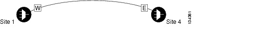
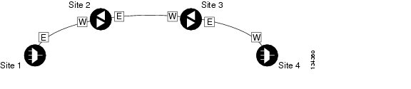
•![]() Point-to-Point—Two terminal sites with the following cards installed:
Point-to-Point—Two terminal sites with the following cards installed:
–![]() 32MUX-O and 32DMX-O cards
32MUX-O and 32DMX-O cards
–![]() 32WSS and 32DMX cards
32WSS and 32DMX cards
–![]() 32WSS and 32-DMX-O cards
32WSS and 32-DMX-O cards
Line amplifiers can be installed between the terminal sites, but intermediate (traffic terminating) sites cannot be installed. Figure 5-2 shows a point-to-point topology as shown in Cisco MetroPlanner.
Figure 5-2 Point-to-Point Topology
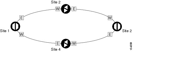
•![]() Two hubs—Two hub nodes in a ring with the following cards installed:
Two hubs—Two hub nodes in a ring with the following cards installed:
–![]() 32MUX-O and 32DMX-O cards
32MUX-O and 32DMX-O cards
–![]() 32WSS and 32DMX cards
32WSS and 32DMX cards
–![]() 32WSS and 32-DMX-O cards
32WSS and 32-DMX-O cards
Line amplifiers can be installed between the hubs. Figure 5-3 shows two hub nodes with no line amplifier nodes installed. Figure 5-4 shows two hub nodes line amplifier nodes installed.
Figure 5-3 Hubs with No Line Amplifiers
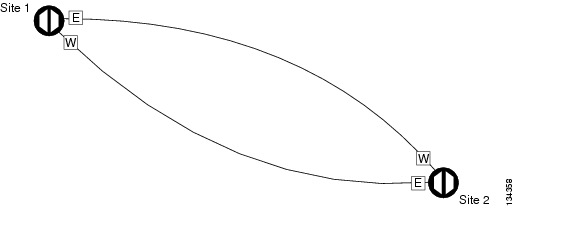
Figure 5-4 Hubs with Line Amplifiers
Step 3 ![]() Return to your originating procedure (NTP).
Return to your originating procedure (NTP).
DLP-G278 Provision the Optical Line Rate
Purpose |
This task provisions the line rate on a multirate PPM. Single-rate PPMs do not need to be provisioned. |
Tools/Equipment |
None |
Prerequisite Procedures |
G277 Provision a Multirate PPM G274 Verify Topologies for ETR_CLO and ISC Services, if you are provisioning an ETR_CLO service. |
Required/As Needed |
Required |
Onsite/Remote |
Onsite or remote |
Security Level |
Provisioning or higher |
Step 1 ![]() In node view, double-click the TXP or MXP card where you want to provision PPM ports. If the data rate you are provisioning is DV-6000, HDTV, ESCON, SDI/D1 Video, ISC-3, or ETR_CLO, complete the following steps. Otherwise, continue with Step 2.
In node view, double-click the TXP or MXP card where you want to provision PPM ports. If the data rate you are provisioning is DV-6000, HDTV, ESCON, SDI/D1 Video, ISC-3, or ETR_CLO, complete the following steps. Otherwise, continue with Step 2.
a. ![]() Click the Provisioning > OTN > OTN Lines tabs.
Click the Provisioning > OTN > OTN Lines tabs.
b. ![]() In the G.709 OTN field, choose Disable.
In the G.709 OTN field, choose Disable.
c. ![]() In the FEC field, choose Disable.
In the FEC field, choose Disable.
d. ![]() Click Apply.
Click Apply.
Step 2 ![]() Click the Provisioning > Pluggable Port Modules tabs.
Click the Provisioning > Pluggable Port Modules tabs.
Step 3 ![]() In the Pluggable Ports area, click Create. The Create Port dialog box appears.
In the Pluggable Ports area, click Create. The Create Port dialog box appears.
Step 4 ![]() In the Create Port dialog box, complete the following:
In the Create Port dialog box, complete the following:
•![]() Port—Choose the PPM number and port number from the drop-down list. The first number indicates the PPM and the second number indicates the port number on the PPM. For example, the first PPM with one port displays as 1-1 and the second PPM with one port displays as 2-1. The PPM number can be 1 to 4, but the port number is always 1.
Port—Choose the PPM number and port number from the drop-down list. The first number indicates the PPM and the second number indicates the port number on the PPM. For example, the first PPM with one port displays as 1-1 and the second PPM with one port displays as 2-1. The PPM number can be 1 to 4, but the port number is always 1.
•![]() Port Type—Choose the type of port from the drop-down list. The port type list displays the supported port rates on your PPM. See Table 5-1 for definitions of the supported rates on the TXP or MXP card.
Port Type—Choose the type of port from the drop-down list. The port type list displays the supported port rates on your PPM. See Table 5-1 for definitions of the supported rates on the TXP or MXP card.
Step 5 ![]() Click OK. The row on the Pluggable Ports area turns light blue until the actual SFP is installed, and then the row turns white.
Click OK. The row on the Pluggable Ports area turns light blue until the actual SFP is installed, and then the row turns white.
Step 6 ![]() Repeat Steps 3 through 5 to configure the port rates as needed.
Repeat Steps 3 through 5 to configure the port rates as needed.
Note ![]() The TXP_MR_10G card is the only TXP or MXP card that does not accept PPMs.
The TXP_MR_10G card is the only TXP or MXP card that does not accept PPMs.
Step 7 ![]() Return to your originating procedure (NTP).
Return to your originating procedure (NTP).
DLP-G279 Change the Optical Line Rate
Purpose |
This task edits PPM port rates for the TXP and MXP cards. Perform this task if you want to change the port rate on a multirate PPM that is already provisioned. |
Tools/Equipment |
None |
Prerequisite Procedures |
G277 Provision a Multirate PPM |
Required/As Needed |
As needed |
Onsite/Remote |
Onsite or remote |
Security Level |
Provisioning or higher |
Step 1 ![]() In node view, double-click the TXP or MXP card where you want to edit the PPM port rate.
In node view, double-click the TXP or MXP card where you want to edit the PPM port rate.
Step 2 ![]() Click the Provisioning > Pluggable Port Modules tabs.
Click the Provisioning > Pluggable Port Modules tabs.
Step 3 ![]() Click the port with the port rate you that want to change in the Pluggable Ports area. The highlight changes to dark blue.
Click the port with the port rate you that want to change in the Pluggable Ports area. The highlight changes to dark blue.
Step 4 ![]() Click Edit. The Edit Port Rate dialog box appears.
Click Edit. The Edit Port Rate dialog box appears.
Step 5 ![]() In the Change To field, use the drop-down list to select the new port rate and click OK. Table 5-1 lists the available rates.
In the Change To field, use the drop-down list to select the new port rate and click OK. Table 5-1 lists the available rates.
Step 6 ![]() Click Yes in the Confirm Port Rate Change dialog box.
Click Yes in the Confirm Port Rate Change dialog box.
Step 7 ![]() Return to your originating procedure (NTP).
Return to your originating procedure (NTP).
DLP-G280 Delete a PPM
Note ![]() This task does not apply to the TXP_MR_10G card.
This task does not apply to the TXP_MR_10G card.
Step 1 ![]() In node view, double-click the TXP or MXP card where you want to delete PPM settings.
In node view, double-click the TXP or MXP card where you want to delete PPM settings.
Step 2 ![]() Click the Provisioning > Pluggable Port Modules tabs.
Click the Provisioning > Pluggable Port Modules tabs.
Step 3 ![]() To delete a PPM and the associated ports:
To delete a PPM and the associated ports:
Note ![]() You cannot delete a port if the client is in the In Service and Normal (IS-NR) (ANSI) or Unlocked-enabled (ETSI) service state, is part of a protection group, has a generic communications channel (GCC) or data communications channel (DCC) in use, is used as a timing source, has circuits, or has overhead circuits. You can delete a port if the trunk is in service and the client is in the OOS-MA,DSBLD (ANSI)/Locked-enabled,disabled (ETSI) service state, with the exception of the last port. You can delete the last port only if the trunk is in a OOS-MA,DSBLD (ANSI)/Locked-enabled,disabled (ETSI) service state.
You cannot delete a port if the client is in the In Service and Normal (IS-NR) (ANSI) or Unlocked-enabled (ETSI) service state, is part of a protection group, has a generic communications channel (GCC) or data communications channel (DCC) in use, is used as a timing source, has circuits, or has overhead circuits. You can delete a port if the trunk is in service and the client is in the OOS-MA,DSBLD (ANSI)/Locked-enabled,disabled (ETSI) service state, with the exception of the last port. You can delete the last port only if the trunk is in a OOS-MA,DSBLD (ANSI)/Locked-enabled,disabled (ETSI) service state.
a. ![]() Click the PPM line that you want to delete that appears in the Pluggable Port Modules area. The highlight changes to dark blue.
Click the PPM line that you want to delete that appears in the Pluggable Port Modules area. The highlight changes to dark blue.
b. ![]() Click Delete. The Delete PPM dialog box appears.
Click Delete. The Delete PPM dialog box appears.
c. ![]() Click Yes. The PPM provisioning is removed from the Pluggable Port Modules area and the Pluggable Ports area.
Click Yes. The PPM provisioning is removed from the Pluggable Port Modules area and the Pluggable Ports area.
Step 4 ![]() Verify that the PPM provisioning is deleted:
Verify that the PPM provisioning is deleted:
•![]() CTC shows an empty slot after the PPM is deleted.
CTC shows an empty slot after the PPM is deleted.
•![]() If the SFP or XFP is physically present when you delete the PPM provisioning, CTC transitions to the deleted state, the ports (if any) are deleted, and the PPM is represented as a gray graphic in CTC. The SFP or XFP can be provisioned again in CTC, or the equipment can be removed, in which case the removal causes the graphic to disappear.
If the SFP or XFP is physically present when you delete the PPM provisioning, CTC transitions to the deleted state, the ports (if any) are deleted, and the PPM is represented as a gray graphic in CTC. The SFP or XFP can be provisioned again in CTC, or the equipment can be removed, in which case the removal causes the graphic to disappear.
Step 5 ![]() If you need to remove the PPM hardware (the SFP or XFP), complete the "DLP-G64 Remove an SFP or XFP" task.
If you need to remove the PPM hardware (the SFP or XFP), complete the "DLP-G64 Remove an SFP or XFP" task.
Step 6 ![]() Return to your originating procedure (NTP).
Return to your originating procedure (NTP).
NTP-G33 Create a Y-Cable Protection Group
Purpose |
This procedure creates a Y-cable protection group between the client ports of two transponder (TXP_MR_10G, TXP_MR_10E, or TXP_MR_2.5G) or two muxponder (MXP_2.5G_10G, MXP_2.5G_10E, MXP_MR_2.5G, MXPP_MR_2.5G) cards. For additional information about Y-cable protection, see the "Y-Cable Protection" section. |
Tools/Equipment |
Installed TXP or MXP cards. Cisco MetroPlanner Traffic Matrix |
Prerequisite Procedures |
G15 Install the Common Control Cards |
Required/As Needed |
As needed |
Onsite/Remote |
Onsite or remote |
Security Level |
Provisioning or higher |
Note ![]() Loss of Pointer Path (LOP-P) alarms can occur on a split signal if the ports are not in a Y-cable protection group.
Loss of Pointer Path (LOP-P) alarms can occur on a split signal if the ports are not in a Y-cable protection group.
Step 1 ![]() View the Cisco MetroPlanner Traffic Matrix (see Table 3-1) for your site. Verify the TXP or MXP cards that need Y-cable protection groups. (Cards requiring Y-cable protection are indicated with "Y-Cable" in the Traffic Matrix table Protection Type column. Refer to the Cisco MetroPlanner DWDM Operations Guide for more information.)
View the Cisco MetroPlanner Traffic Matrix (see Table 3-1) for your site. Verify the TXP or MXP cards that need Y-cable protection groups. (Cards requiring Y-cable protection are indicated with "Y-Cable" in the Traffic Matrix table Protection Type column. Refer to the Cisco MetroPlanner DWDM Operations Guide for more information.)
Step 2 ![]() Verify that the TXP or MXP cards are installed according to the requirements specified in Table 5-2. This table describes the protection types available in the ONS 15454 for DWDM client cards.
Verify that the TXP or MXP cards are installed according to the requirements specified in Table 5-2. This table describes the protection types available in the ONS 15454 for DWDM client cards.
Step 3 ![]() Verify that PPMs are provisioned for the same payload and payload rate on the TXP and MXP cards where you will create the Y-cable protection group.
Verify that PPMs are provisioned for the same payload and payload rate on the TXP and MXP cards where you will create the Y-cable protection group.
•![]() Display the TXP or MXP card in card view. Click the Provisioning > Pluggable Port Module tabs. Verify that a PPM is provisioned in the Pluggable Port Module area, and the payload type and rate is provisioned for it in the Selected PPM area.
Display the TXP or MXP card in card view. Click the Provisioning > Pluggable Port Module tabs. Verify that a PPM is provisioned in the Pluggable Port Module area, and the payload type and rate is provisioned for it in the Selected PPM area.
The PPM payload and payload rate must be the same for both TXP or MXP cards. If they are not the same, for example, if the PPM payload and payload rate are not the same, you must either change the provisioned payload rate to match, or replace the PPM (SFP or XFP).
Step 4 ![]() In node view, click the Provisioning > Protection tabs.
In node view, click the Provisioning > Protection tabs.
Step 5 ![]() In the Protection Groups area, click Create.
In the Protection Groups area, click Create.
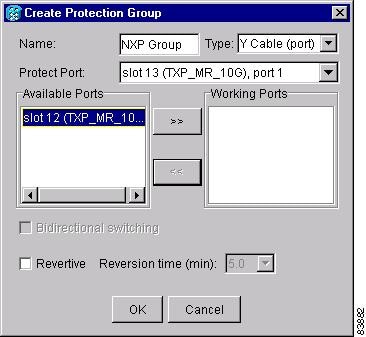
Step 6 ![]() In the Create Protection Group dialog box, enter the following:
In the Create Protection Group dialog box, enter the following:
•![]() Name—Type a name for the protection group. The name can have up to 32 alphanumeric (a-z, A-Z, 0-9) characters. Special characters are permitted. For TL1 compatibility, do not use question mark (?), backslash (\), or double quote (") characters.
Name—Type a name for the protection group. The name can have up to 32 alphanumeric (a-z, A-Z, 0-9) characters. Special characters are permitted. For TL1 compatibility, do not use question mark (?), backslash (\), or double quote (") characters.
•![]() Type—Choose Y Cable from the drop-down list.
Type—Choose Y Cable from the drop-down list.
•![]() Protect Port—From the drop-down list, choose the port that will be the standby or protection port to the active port. The list displays the available transponder or muxponder ports. If transponder or muxponder cards are not installed, no ports appear in the drop-down list.
Protect Port—From the drop-down list, choose the port that will be the standby or protection port to the active port. The list displays the available transponder or muxponder ports. If transponder or muxponder cards are not installed, no ports appear in the drop-down list.
After you choose the protect port, a list of available working ports appear in the Available Ports list, as shown in Figure 5-5. If no cards are available, no ports appear. If this occurs, you can not complete this task until you install the physical cards or preprovision the ONS 15454 slots using the "NTP-G29 Preprovision a Slot" procedure.
Figure 5-5 Creating a Y-Cable Protection Group
Step 7 ![]() From the Available Ports list, choose the port that will be protected by the port you selected in Protect Ports. Click the top arrow button to move the port to the Working Ports list.
From the Available Ports list, choose the port that will be protected by the port you selected in Protect Ports. Click the top arrow button to move the port to the Working Ports list.
Step 8 ![]() Complete the remaining fields:
Complete the remaining fields:
•![]() Revertive—Check this check box if you want traffic to revert to the working port after failure conditions remain corrected for the amount of time entered in the Reversion Time field.
Revertive—Check this check box if you want traffic to revert to the working port after failure conditions remain corrected for the amount of time entered in the Reversion Time field.
•![]() Reversion time—If Revertive is checked, select a reversion time from the drop-down list. The range is 0.5 to 12.0 minutes. The default is 5.0 minutes. Reversion time is the amount of time that will elapse before the traffic reverts to the working card. The reversion timer starts after conditions causing the switch are cleared.
Reversion time—If Revertive is checked, select a reversion time from the drop-down list. The range is 0.5 to 12.0 minutes. The default is 5.0 minutes. Reversion time is the amount of time that will elapse before the traffic reverts to the working card. The reversion timer starts after conditions causing the switch are cleared.
Step 9 ![]() Click OK.
Click OK.
Step 10 ![]() Repeat this procedure for every protection indicated in the Cisco MetroPlanner Traffic Matrix.
Repeat this procedure for every protection indicated in the Cisco MetroPlanner Traffic Matrix.
Stop. You have completed this procedure.
NTP-G96 Modify Line Settings and PM Parameter Thresholds for TXP_MR_10G and TXP_MR_10E Cards
Purpose |
This procedure changes the line and threshold settings for TXP_MR_10G and TXP_MR_10E cards. |
Tools/Equipment |
None |
Prerequisite Procedures |
G32 Install the Transponder and Muxponder Cards G277 Provision a Multirate PPM (if necessary) G278 Provision the Optical Line Rate (if necessary) |
Required/As Needed |
As needed |
Onsite/Remote |
Onsite or remote |
Security Level |
Provisioning or higher |
Note ![]() The TXP_MR_10G card does not support PPMs.
The TXP_MR_10G card does not support PPMs.
Step 1 ![]() Complete the "DLP-G46 Log into CTC" task at the node where you want to change the transponder card settings. If you are already logged in, continue with Step 2.
Complete the "DLP-G46 Log into CTC" task at the node where you want to change the transponder card settings. If you are already logged in, continue with Step 2.
Step 2 ![]() As needed, complete the "NTP-G103 Back Up the Database" procedure to preserve the existing transmission settings.
As needed, complete the "NTP-G103 Back Up the Database" procedure to preserve the existing transmission settings.
Step 3 ![]() Perform any of the following tasks as needed:
Perform any of the following tasks as needed:
•![]() G216 Change Card Settings for TXP_MR_10G and TXP_MR_10E Cards
G216 Change Card Settings for TXP_MR_10G and TXP_MR_10E Cards
•![]() G217 Change Line Settings for TXP_MR_10G and TXP_MR_10E Cards
G217 Change Line Settings for TXP_MR_10G and TXP_MR_10E Cards
•![]() G218 Change Section Trace Settings for the TXP_MR_10G and TXP_MR_10E Cards
G218 Change Section Trace Settings for the TXP_MR_10G and TXP_MR_10E Cards
•![]() G219 Change the TXP_MR_10G or TXP_MR_10E Card Line Thresholds for SONET or SDH Payloads
G219 Change the TXP_MR_10G or TXP_MR_10E Card Line Thresholds for SONET or SDH Payloads
•![]() G319 Change the TXP_MR_10G or TXP_MR_10E Card Line Thresholds for 10G Ethernet LAN Phy
G319 Change the TXP_MR_10G or TXP_MR_10E Card Line Thresholds for 10G Ethernet LAN Phy
•![]() G301 Provision the TXP_MR_10G and TXP_MR_10E Trunk Port Alarm and TCA Thresholds
G301 Provision the TXP_MR_10G and TXP_MR_10E Trunk Port Alarm and TCA Thresholds
•![]() G302 Provision the TXP_MR_10G and TXP_MR_10E Client Port Alarm and TCA Thresholds
G302 Provision the TXP_MR_10G and TXP_MR_10E Client Port Alarm and TCA Thresholds
•![]() G221 Change OTN Settings for TXP_MR_10G and TXP_MR_10E Cards
G221 Change OTN Settings for TXP_MR_10G and TXP_MR_10E Cards
Stop. You have completed this procedure.
DLP-G216 Change Card Settings for TXP_MR_10G and TXP_MR_10E Cards
Step 1 ![]() In node view, double-click the TXP_MR_10G or TXP_MR_10E card where you want to change the card settings.
In node view, double-click the TXP_MR_10G or TXP_MR_10E card where you want to change the card settings.
Step 2 ![]() Click the Provisioning > Card tabs.
Click the Provisioning > Card tabs.
Step 3 ![]() Modify any of the settings described in Table 5-3.
Modify any of the settings described in Table 5-3.
|
|
|
|
|
|---|---|---|---|
Termination Mode |
Sets the mode of operation. See the "Termination Modes" section for more details. |
• • • |
• • • |
AIS/Squelch |
(TXP_MR_10E only) Sets the transparent termination mode configuration. |
• • |
• • |
Wavelength |
Sets the wavelength of the DWDM side optical transmitter. |
• • • Note |
• • • Note |
Step 4 ![]() Click Apply.
Click Apply.
Step 5 ![]() Return to your originating procedure (NTP).
Return to your originating procedure (NTP).
DLP-G217 Change Line Settings for TXP_MR_10G and TXP_MR_10E Cards
Step 1 ![]() In node view, double-click the TXP_MR_10G or TXP_MR_10E card where you want to change the line settings.
In node view, double-click the TXP_MR_10G or TXP_MR_10E card where you want to change the line settings.
Step 2 ![]() Click the Provisioning > Line > SONET (including 10G Ethernet WAN phy) tabs.
Click the Provisioning > Line > SONET (including 10G Ethernet WAN phy) tabs.
Step 3 ![]() Modify any of the settings described in Table 5-4.
Modify any of the settings described in Table 5-4.
Note ![]() In Table 5-4, some parameter tabs do not always apply to both the TXP_MR_10G cards and the TXP_MR_10E cards. If a tab does not apply, it will not appear in CTC.
In Table 5-4, some parameter tabs do not always apply to both the TXP_MR_10G cards and the TXP_MR_10E cards. If a tab does not apply, it will not appear in CTC.
|
|
|
|
|
|---|---|---|---|
Port |
(Display only) Displays the port number. |
• • |
• • |
Port Name |
Provides the ability to assign the specified port a name. |
User-defined. Name can be up to 32 alphanumeric/special characters. Blank by default. |
User-defined. Name can be up to 32 alphanumeric/special characters. Blank by default. |
Admin State |
Sets the port service state. For more information about administrative states, see "DWDM Administrative and Service States." |
• • • • |
• • • • |
Service State |
(Display only) Identifies the autonomously generated state that gives the overall condition of the port. Service states appear in the format: Primary State-Primary State Qualifier, Secondary State. For more information about service states, see "DWDM Administrative and Service States." |
• • • • |
• • • • |
SF BER |
(SONET [ANSI] or SDH [ETSI] including 10G Ethernet WAN Phy only) Sets the signal fail bit error rate. |
• • • |
• • • |
SD BER |
(SONET [ANSI] or SDH [ETSI] including 10G Ethernet WAN Phy only) Sets the signal degrade bit error rate. |
• • • • • |
• • • • • |
AINS Soak |
(SONET [ANSI] or SDH [ETSI] including 10G Ethernet WAN Phy only) Sets the automatic in-service soak period. Double-click the time and use the up and down arrows to change settings. |
• • |
• • |
Type |
(SONET [ANSI] or SDH [ETSI] including 10G Ethernet WAN Phy only) The optical transport type. |
• • |
• • |
ALS Mode |
Sets the automatic laser shutdown (ALS) function mode. The DWDM transmitter supports ALS according to ITU-T G.644 (06/99). ALS can be disabled, or it can be set for one of three mode options. |
• • • • |
• • • • |
ProvidesSync |
(TXP_MR_10E, OC192 only) Sets the ProvidesSync card parameter. If checked, the card is provisioned as a network element (NE) timing reference. |
Checked or unchecked |
Checked or unchecked |
SyncMsgIn |
(TXP_MR_10E, OC192 only) Sets the EnableSync card parameter. Enables synchronization status messages (S1 byte), which allow the node to choose the best timing source. |
Checked or unchecked |
Checked or unchecked |
Send DoNotUse |
(TXP_MR_10E, OC192 only) Sets the Send DoNotUse card state. When checked, sends a do not use (DUS) message on the S1 byte. |
Checked or unchecked |
Checked or unchecked |
Max Size |
(TXP_MR_10E, 10_GE LAN Phy only) Sets the maximum Ethernet packet size. |
• • |
• • |
Incoming MAC Address |
(TXP_MR_10E, 10_GE LAN Phy only) Sets the incoming MAC address. |
Value of MAC address. 6 bytes in hexadecimal format. |
Value of MAC address. 6 bytes in hexadecimal format. |
Wavelength |
Displays the wavelength of the client port. |
• • • |
• • • |
Reach |
Displays the optical reach distance of the client port. |
• |
• |
Step 4 ![]() Click Apply.
Click Apply.
Step 5 ![]() Return to your originating procedure (NTP).
Return to your originating procedure (NTP).
DLP-G218 Change Section Trace Settings for the TXP_MR_10G and TXP_MR_10E Cards
Note ![]() The Section Trace tab is available for the TXP_MR_10G and TXP_MR_10E cards only if no PPM or an OC192 PPM has been provisioned. The tab is not available if a TEN_GE LAN Phy or FC10G PPM has been provisioned.
The Section Trace tab is available for the TXP_MR_10G and TXP_MR_10E cards only if no PPM or an OC192 PPM has been provisioned. The tab is not available if a TEN_GE LAN Phy or FC10G PPM has been provisioned.
Step 1 ![]() In node view, double-click the TXP_MR_10G or TXP_MR_10E card where you want to change the section trace settings.
In node view, double-click the TXP_MR_10G or TXP_MR_10E card where you want to change the section trace settings.
Step 2 ![]() Click the Provisioning > Line > Section Trace tabs.
Click the Provisioning > Line > Section Trace tabs.
Step 3 ![]() Modify any of the settings described in Table 5-5.
Modify any of the settings described in Table 5-5.
Step 4 ![]() Click Apply.
Click Apply.
Step 5 ![]() Return to your originating procedure (NTP).
Return to your originating procedure (NTP).
DLP-G219 Change the TXP_MR_10G or TXP_MR_10E Card Line Thresholds for SONET or SDH Payloads
Step 1 ![]() In node view, double-click the TXP_MR_10G or TXP_MR_10E card where you want to change the line threshold settings.
In node view, double-click the TXP_MR_10G or TXP_MR_10E card where you want to change the line threshold settings.
Step 2 ![]() Click the Provisioning > Line Thresholds > SONET Thresholds tabs.
Click the Provisioning > Line Thresholds > SONET Thresholds tabs.
Step 3 ![]() Modify any of the settings described in Table 5-6.
Modify any of the settings described in Table 5-6.
Note ![]() You must modify Near End and Far End independently; 15 Min and 1 Day independently; and Line and Section independently. To do so, choose the appropriate radio button and click Refresh.
You must modify Near End and Far End independently; 15 Min and 1 Day independently; and Line and Section independently. To do so, choose the appropriate radio button and click Refresh.
Step 4 ![]() Click Apply.
Click Apply.
Step 5 ![]() Return to your originating procedure (NTP).
Return to your originating procedure (NTP).
DLP-G319 Change the TXP_MR_10G or TXP_MR_10E Card Line Thresholds for 10G Ethernet LAN Phy
Step 1 ![]() Display the TXP_MR_10G or TXP_MR_10E card where you want to change the line threshold settings in card view.
Display the TXP_MR_10G or TXP_MR_10E card where you want to change the line threshold settings in card view.
Step 2 ![]() Click the Provisioning > Line Thresholds > RMON Thresholds tabs.
Click the Provisioning > Line Thresholds > RMON Thresholds tabs.
Step 3 ![]() Click Create. The Create Threshold dialog box appears.
Click Create. The Create Threshold dialog box appears.
Step 4 ![]() From the Port drop-down list, choose the applicable port.
From the Port drop-down list, choose the applicable port.
Step 5 ![]() From the Variable drop-down list, choose an Ethernet variable. See Table 5-7 for a list of available Ethernet thresholds.
From the Variable drop-down list, choose an Ethernet variable. See Table 5-7 for a list of available Ethernet thresholds.
Step 6 ![]() From the Alarm Type drop-down list, indicate whether the event will be triggered by the rising threshold, falling threshold, or both the rising and falling thresholds.
From the Alarm Type drop-down list, indicate whether the event will be triggered by the rising threshold, falling threshold, or both the rising and falling thresholds.
Step 7 ![]() From the Sample Type drop-down list, choose either Relative or Absolute. Relative restricts the threshold to use the number of occurrences in the user-set sample period. Absolute sets the threshold to use the total number of occurrences, regardless of time period.
From the Sample Type drop-down list, choose either Relative or Absolute. Relative restricts the threshold to use the number of occurrences in the user-set sample period. Absolute sets the threshold to use the total number of occurrences, regardless of time period.
Step 8 ![]() Type in an appropriate number of seconds for the Sample Period.
Type in an appropriate number of seconds for the Sample Period.
Step 9 ![]() Type in the appropriate number of occurrences for the Rising Threshold.
Type in the appropriate number of occurrences for the Rising Threshold.
For a rising type of alarm, the measured value must move from below the falling threshold to above the rising threshold. For example, if a network is running below a rising threshold of 1000 collisions every 15 seconds and a problem causes 1001 collisions in 15 seconds, the excess occurrences trigger an alarm.
Step 10 ![]() Enter the appropriate number of occurrences in the Falling Threshold field. In most cases a falling threshold is set lower than the rising threshold.
Enter the appropriate number of occurrences in the Falling Threshold field. In most cases a falling threshold is set lower than the rising threshold.
A falling threshold is the counterpart to a rising threshold. When the number of occurrences is above the rising threshold and then drops below a falling threshold, it resets the rising threshold. For example, when the network problem that caused 1001 collisions in 15 seconds subsides and creates only 799 collisions in 15 seconds, occurrences fall below a falling threshold of 800 collisions. This resets the rising threshold so that if network collisions again spike over a 1000 per 15-second period, an event again triggers when the rising threshold is crossed. An event is triggered only the first time a rising threshold is exceeded (otherwise, a single network problem might cause a rising threshold to be exceeded multiple times and cause a flood of events).
Step 11 ![]() Click OK.
Click OK.
Step 12 ![]() Return to your originating procedure (NTP).
Return to your originating procedure (NTP).
DLP-G301 Provision the TXP_MR_10G and TXP_MR_10E Trunk Port Alarm and TCA Thresholds
Step 1 ![]() In node view, double-click the TXP_MR_10G or TXP_MR_10E card where you want to change the trunk port alarm and TCA settings.
In node view, double-click the TXP_MR_10G or TXP_MR_10E card where you want to change the trunk port alarm and TCA settings.
Step 2 ![]() Click the Provisioning > Optics Thresholds tabs.
Click the Provisioning > Optics Thresholds tabs.
Step 3 ![]() Referring to Table 5-8, provision the trunk port (Port 2) TCA thresholds for RX Power High, RX Power Low, TX Power High, and TX Power Low.
Referring to Table 5-8, provision the trunk port (Port 2) TCA thresholds for RX Power High, RX Power Low, TX Power High, and TX Power Low.
Note ![]() You must modify 15 Min and 1 Day independently. To do so, choose the appropriate radio button and click Refresh.
You must modify 15 Min and 1 Day independently. To do so, choose the appropriate radio button and click Refresh.
Note ![]() Do not modify the Laser Bias parameters.
Do not modify the Laser Bias parameters.
Step 4 ![]() Click Apply.
Click Apply.
Step 5 ![]() Under Types, click the Alarm radio button and click Refresh.
Under Types, click the Alarm radio button and click Refresh.
Step 6 ![]() Referring to Table 5-9, provision the trunk port (Port 2) Alarm thresholds for RX Power High, RX Power Low, TX Power High, and TX Power Low.
Referring to Table 5-9, provision the trunk port (Port 2) Alarm thresholds for RX Power High, RX Power Low, TX Power High, and TX Power Low.
Note ![]() You must modify 15 Min and 1 Day independently. To do so, choose the appropriate radio button and click Refresh.
You must modify 15 Min and 1 Day independently. To do so, choose the appropriate radio button and click Refresh.
Step 7 ![]() Click Apply.
Click Apply.
Step 8 ![]() Return to your originating procedure (NTP).
Return to your originating procedure (NTP).
DLP-G302 Provision the TXP_MR_10G and TXP_MR_10E Client Port Alarm and TCA Thresholds
Purpose |
This task provisions the client port alarm and TCA thresholds for the TXP_MR_10G and TXP_MR_10E cards. |
Tools/Equipment |
None |
Prerequisite Procedures |
G278 Provision the Optical Line Rate |
Required/As Needed |
Required |
Onsite/Remote |
Onsite or remote |
Security Level |
Provisioning or higher |
Step 1 ![]() In node view, double-click the TXP_MR_10G or TXP_MR_10E card where you want to change the client port alarm and TCA settings.
In node view, double-click the TXP_MR_10G or TXP_MR_10E card where you want to change the client port alarm and TCA settings.
Step 2 ![]() Click the Provisioning > Optics Thresholds tabs. The TCA thresholds are shown by default.
Click the Provisioning > Optics Thresholds tabs. The TCA thresholds are shown by default.
Step 3 ![]() Referring to Table 5-10, provision the Port 1 (Client) TCA thresholds for RX Power High, RX Power Low, TX Power High, and TX Power Low based on the client interface at the other end. For additional information about client SFP and XFP interfaces, also known as PPMs, refer to "Hardware Specifications."
Referring to Table 5-10, provision the Port 1 (Client) TCA thresholds for RX Power High, RX Power Low, TX Power High, and TX Power Low based on the client interface at the other end. For additional information about client SFP and XFP interfaces, also known as PPMs, refer to "Hardware Specifications."
Note ![]() You must modify 15 Min and 1 Day independently. To do so, choose the appropriate radio button and click Refresh.
You must modify 15 Min and 1 Day independently. To do so, choose the appropriate radio button and click Refresh.
Note ![]() Do not modify the Laser Bias parameters.
Do not modify the Laser Bias parameters.
Step 4 ![]() Click Apply.
Click Apply.
Step 5 ![]() Under Types, click the Alarm radio button and click Refresh.
Under Types, click the Alarm radio button and click Refresh.
Step 6 ![]() Referring to Table 5-11, provision the Port 1 (Client) Alarm thresholds for RX Power High, RX Power Low, TX Power High, and TX Power Low based on the client interface that is provisioned.
Referring to Table 5-11, provision the Port 1 (Client) Alarm thresholds for RX Power High, RX Power Low, TX Power High, and TX Power Low based on the client interface that is provisioned.
Note ![]() You must modify 15 Min and 1 Day independently. To do so, choose the appropriate radio button and click Refresh.
You must modify 15 Min and 1 Day independently. To do so, choose the appropriate radio button and click Refresh.
Step 7 ![]() Click Apply.
Click Apply.
Step 8 ![]() Return to your originating procedure (NTP).
Return to your originating procedure (NTP).
DLP-G221 Change OTN Settings for TXP_MR_10G and TXP_MR_10E Cards
Step 1 ![]() In node view, double-click the TXP_MR_10G or TXP_MR_10E card where you want to change the OTN settings.
In node view, double-click the TXP_MR_10G or TXP_MR_10E card where you want to change the OTN settings.
Step 2 ![]() Click one of the Provisioning > OTN tabs, then click one of the following subtabs: OTN Lines, G.709 Thresholds, FEC Thresholds, or Trail Trace Identifier.
Click one of the Provisioning > OTN tabs, then click one of the following subtabs: OTN Lines, G.709 Thresholds, FEC Thresholds, or Trail Trace Identifier.
Step 3 ![]() Modify any of the settings described in Tables 5-12 through 5-15.
Modify any of the settings described in Tables 5-12 through 5-15.
Note ![]() You must modify Near End, and Far End independently; 15 Min and 1 Day independently; and SM and PM independently. To do so, choose the appropriate radio button and click Refresh.
You must modify Near End, and Far End independently; 15 Min and 1 Day independently; and SM and PM independently. To do so, choose the appropriate radio button and click Refresh.
Table 5-12 describes the values on the Provisioning > OTN > OTN Lines tab.
Table 5-13 describes the values on the Provisioning > OTN > G.709 Thresholds tab.
Table 5-14 describes the values on the Provisioning > OTN > FEC Thresholds tab.
Table 5-15 describes the values on the Provisioning > OTN > Trail Trace Identifier tab.
Step 4 ![]() Click Apply.
Click Apply.
Step 5 ![]() Return to your originating procedure (NTP).
Return to your originating procedure (NTP).
NTP-G97 Modify Line Settings and PM Parameter Thresholds for MXP_2.5G_10G and MXP_2.5G_10E Cards
Purpose |
This procedure changes the line and threshold settings for MXP_2.5G_10G and MXP_2.5G_10E muxponder cards. |
Tools/Equipment |
None |
Prerequisite Procedures |
G32 Install the Transponder and Muxponder Cards. G277 Provision a Multirate PPM (if necessary) G278 Provision the Optical Line Rate (if necessary) |
Required/As Needed |
As needed |
Onsite/Remote |
Onsite or remote |
Security Level |
Provisioning or higher |
Step 1 ![]() Complete the "DLP-G46 Log into CTC" task at the node where you want to change the muxponder card settings. If you are already logged in, continue with Step 2.
Complete the "DLP-G46 Log into CTC" task at the node where you want to change the muxponder card settings. If you are already logged in, continue with Step 2.
Step 2 ![]() As needed, complete the "NTP-G103 Back Up the Database" procedure to preserve the existing transmission settings.
As needed, complete the "NTP-G103 Back Up the Database" procedure to preserve the existing transmission settings.
Step 3 ![]() Perform any of the following tasks as needed:
Perform any of the following tasks as needed:
•![]() G222 Change Card Settings for MXP_2.5G_10G and MXP_2.5G_10E Cards
G222 Change Card Settings for MXP_2.5G_10G and MXP_2.5G_10E Cards
•![]() G223 Change Line Settings for MXP_2.5G_10G and MXP_2.5G_10E Cards
G223 Change Line Settings for MXP_2.5G_10G and MXP_2.5G_10E Cards
•![]() G224 Change Section Trace Settings for MXP_2.5G_10G and MXP_2.5G_10E Cards
G224 Change Section Trace Settings for MXP_2.5G_10G and MXP_2.5G_10E Cards
•![]() G225 Change Trunk Settings for MXP_2.5G_10G and MXP_2.5G_10E Cards
G225 Change Trunk Settings for MXP_2.5G_10G and MXP_2.5G_10E Cards
•![]() G226 Change Line Thresholds Settings for MXP_2.5G_10G and MXP_2.5G_10E Cards
G226 Change Line Thresholds Settings for MXP_2.5G_10G and MXP_2.5G_10E Cards
•![]() G303 Provision the MXP_2.5G_10G and MXP_2.5G_10E Trunk Port Alarm and TCA Thresholds
G303 Provision the MXP_2.5G_10G and MXP_2.5G_10E Trunk Port Alarm and TCA Thresholds
•![]() G304 Provision the MXP_2.5G_10G and MXP_2.5G_10E Client Port Alarm and TCA Thresholds
G304 Provision the MXP_2.5G_10G and MXP_2.5G_10E Client Port Alarm and TCA Thresholds
•![]() G228 Change Line OTN Settings for MXP_2.5G_10G and MXP_2.5G_10E Cards
G228 Change Line OTN Settings for MXP_2.5G_10G and MXP_2.5G_10E Cards
Step 4 ![]() As needed, complete the "NTP-G103 Back Up the Database" procedure.
As needed, complete the "NTP-G103 Back Up the Database" procedure.
Stop. You have completed this procedure.
DLP-G222 Change Card Settings for MXP_2.5G_10G and MXP_2.5G_10E Cards
Step 1 ![]() In node view, double-click the MXP_2.5G_10G or and MXP_2.5G_10E card where you want to change the card settings.
In node view, double-click the MXP_2.5G_10G or and MXP_2.5G_10E card where you want to change the card settings.
Step 2 ![]() Click the Provisioning > Card tabs.
Click the Provisioning > Card tabs.
Step 3 ![]() Modify any of the settings described in Table 5-16.
Modify any of the settings described in Table 5-16.
|
|
|
|
|---|---|---|
Termination Mode |
Sets the mode of operation. Options that do not apply to a card do not display. The MXP_2.5G_10G card is based on SONET/SDH multiplexing. The transparent mode terminates and rebuilds the B1 byte (as well as other bytes) of the incoming OC-48/STM-16 signal. The B2 byte is not touched. The MXP_2.5G_10E card is fully transparent in transparent mode based on the OTN/ITU-T G.709 multiplexing scheme. It does not terminate the B1 byte or other bytes. It encapsulates OC-48/STM-16 bytes into ODU1 first, then multiplexes them into an OTU2. See the "Termination Modes" section for more information. |
For ANSI platforms: • • • For ETSI platforms: • • • |
Wavelength |
Sets the wavelength of the DWDM side optical transmitter. You can set the wavelength to the First Tunable Wavelength or to further wavelengths in 100 GHz ITU spacing. |
• • • Note |
AIS/Squelch |
(MXP_2.5G_10E only) Sets the transparent termination mode configuration. |
• • |
Card Parameters |
Displays the settings for the card. |
Display only |
Step 4 ![]() Click Apply.
Click Apply.
Step 5 ![]() Return to your originating procedure (NTP).
Return to your originating procedure (NTP).
DLP-G223 Change Line Settings for MXP_2.5G_10G and MXP_2.5G_10E Cards
Step 1 ![]() Double-click the MXP_2.5G_10G or MXP_2.5G_10E card where you want to change the line settings.
Double-click the MXP_2.5G_10G or MXP_2.5G_10E card where you want to change the line settings.
Step 2 ![]() Click the Provisioning > Line > SONET (ANSI) or SDH (ETSI) tabs.
Click the Provisioning > Line > SONET (ANSI) or SDH (ETSI) tabs.
Note ![]() The SONET tab appears only if you have created a PPM for a given port.
The SONET tab appears only if you have created a PPM for a given port.
Step 3 ![]() Modify any of the settings described in Table 5-17.
Modify any of the settings described in Table 5-17.
Note ![]() You must modify Near End, and Far End independently; 15 Min and 1 Day independently; and Line and Section independently. To do so, choose the appropriate radio button and click Refresh.
You must modify Near End, and Far End independently; 15 Min and 1 Day independently; and Line and Section independently. To do so, choose the appropriate radio button and click Refresh.
|
|
|
|
|---|---|---|
Port # |
(Display only) Port number. Ports 1 to 4 are client ports (OC-48/STM-16). Port 5 (TXP_2.5G_10G) is the DWDM trunk (OC-192/STM-64) that provides wavelength services. |
• • • • • |
Port Name |
Provides the ability to assign the specified port a logical name. |
User-defined. Name can be up to 32 alphanumeric/ special characters. Blank by default. |
Admin State |
Sets the port service state unless network conditions prevent the change. For more information about administrative states, see "DWDM Administrative and Service States." |
• • • • |
Service State |
Identifies the autonomously generated state that gives the overall condition of the port. Service states appear in the format: Primary State-Primary State Qualifier, Secondary State. For more information about service states, see "DWDM Administrative and Service States." |
• • • • |
ALS Mode |
Sets the ALS function mode. The DWDM transmitter supports ALS according to ITU-T G.644 (06/99). ALS can be disabled or can be set for one of three mode options. |
• • • • |
SF BER |
Sets the signal fail bit error rate. |
• • • |
SD BER |
Sets the signal degrade bit error rate. |
• • • • • |
AINS Soak |
Sets the automatic in-service soak period. Double-click the time and use the up and down arrows to change settings. |
• • |
Type |
Sets the optical transport type. |
• • |
ProvidesSync |
Sets the ProvidesSync card parameter. If checked, the card is provisioned as an NE timing reference. (This parameter does not appear for the MXP_2.5G_10E trunk port.) |
Checked or unchecked |
SyncMsgIn |
Enables synchronization status messages (S1 byte), which allow the node to choose the best timing source. (This parameter does not appear for the MXP_2.5G_10E trunk port.) |
Checked or unchecked |
Send DoNotUse |
When checked, sends a DUS message on the S1 byte. (This parameter does not appear for the MXP_2.5G_10E trunk port.) |
Checked or unchecked |
Reach |
Displays the optical reach distance of the client port. |
• • • • • • • |
Wavelength |
Displays the wavelength of the client port. |
• • • |
Step 4 ![]() Click Apply.
Click Apply.
Step 5 ![]() Return to your originating procedure (NTP).
Return to your originating procedure (NTP).
DLP-G224 Change Section Trace Settings for MXP_2.5G_10G and MXP_2.5G_10E Cards
Note ![]() The Section Trace tab appears only if you have created a PPM for the card.
The Section Trace tab appears only if you have created a PPM for the card.
Step 6 ![]() In node view, double-click the MXP_2.5G_10G or MXP_2.5G_10E card where you want to change the section trace settings.
In node view, double-click the MXP_2.5G_10G or MXP_2.5G_10E card where you want to change the section trace settings.
Step 7 ![]() Click the Provisioning > Line > Section Trace tabs.
Click the Provisioning > Line > Section Trace tabs.
Step 8 ![]() Modify any of the settings described in Table 5-18.
Modify any of the settings described in Table 5-18.
Step 9 ![]() Click Apply.
Click Apply.
Step 10 ![]() Return to your originating procedure (NTP).
Return to your originating procedure (NTP).
DLP-G225 Change Trunk Settings for MXP_2.5G_10G and MXP_2.5G_10E Cards
Step 1 ![]() In node view, double-click the MXP_2.5G_10G or MXP_2.5G_10E card where you want to change the section trace settings.
In node view, double-click the MXP_2.5G_10G or MXP_2.5G_10E card where you want to change the section trace settings.
Step 2 ![]() Click the Provisioning > Line > Trunk tab.
Click the Provisioning > Line > Trunk tab.
Step 3 ![]() Modify any of the settings described in Table 5-19.
Modify any of the settings described in Table 5-19.
|
|
|
|
|---|---|---|
Port # |
(Display only) Displays the port number. Port 5 is the DWDM trunk (OC-192/STM-64) that provides wavelength services. |
5 |
Port Name |
Provides the ability to assign the specified port a logical name. |
User-defined. Name can be up to 32 alphanumeric/ special characters. Blank by default. |
Admin State |
Sets the port service state unless network conditions prevent the change. For more information about administrative states, see "DWDM Administrative and Service States." |
• • • • |
Service State |
Identifies the autonomously generated state that gives the overall condition of the port. Service states appear in the format: Primary State-Primary State Qualifier, Secondary State. For more information about service states, see "DWDM Administrative and Service States." |
• • • • |
ALS Mode |
Sets the ALS function mode. The DWDM transmitter supports ALS according to ITU-T G.644 (06/99). ALS can be disabled or can be set for one of three mode options. |
• • • • |
AINS Soak |
(OC-N and STM-N payloads only) Sets the automatic in-service soak period. |
• • |
Step 4 ![]() Click Apply.
Click Apply.
Step 5 ![]() Return to your originating procedure (NTP).
Return to your originating procedure (NTP).
DLP-G226 Change Line Thresholds Settings for MXP_2.5G_10G and MXP_2.5G_10E Cards
Step 1 ![]() In node view, double-click the MXP_2.5G_10G or MXP_2.5G_10E card where you want to change the line threshold settings.
In node view, double-click the MXP_2.5G_10G or MXP_2.5G_10E card where you want to change the line threshold settings.
Step 2 ![]() Click the Provisioning > Line Thresholds tabs.
Click the Provisioning > Line Thresholds tabs.
Step 3 ![]() Modify any of the settings described in Table 5-18.
Modify any of the settings described in Table 5-18.
Note ![]() You must modify Near End, and Far End independently; 15 Min and 1 Day independently; and Line or Multiplex Section and Section or Regeneration Section independently. To do so, choose the appropriate radio button and click Refresh.
You must modify Near End, and Far End independently; 15 Min and 1 Day independently; and Line or Multiplex Section and Section or Regeneration Section independently. To do so, choose the appropriate radio button and click Refresh.
Note ![]() In Table 5-20, some parameter tabs or selections do not always apply to both the MXP_2.5G_10G and the MXP_2.5G_10E card. If the tabs or selections do not apply, they do not appear in CTC.
In Table 5-20, some parameter tabs or selections do not always apply to both the MXP_2.5G_10G and the MXP_2.5G_10E card. If the tabs or selections do not apply, they do not appear in CTC.
Step 4 ![]() Click Apply.
Click Apply.
Step 5 ![]() Return to your originating procedure (NTP).
Return to your originating procedure (NTP).
DLP-G303 Provision the MXP_2.5G_10G and MXP_2.5G_10E Trunk Port Alarm and TCA Thresholds
Step 1 ![]() In node view, double-click the MXP_2.5G_10G or MXP_2.5G_10E card where you want to change the trunk port alarm and TCA settings.
In node view, double-click the MXP_2.5G_10G or MXP_2.5G_10E card where you want to change the trunk port alarm and TCA settings.
Step 2 ![]() Click the Provisioning > Optics Thresholds tabs.
Click the Provisioning > Optics Thresholds tabs.
Step 3 ![]() Select a 15 Min or 1 Day PM interval radio button and then click Refresh.
Select a 15 Min or 1 Day PM interval radio button and then click Refresh.
Note ![]() You must modify 15 Min and 1 Day independently. To do so, choose the appropriate radio button and click Refresh.
You must modify 15 Min and 1 Day independently. To do so, choose the appropriate radio button and click Refresh.
Step 4 ![]() Referring to Table 5-21, provision the trunk port (Port 5) TCA thresholds for RX Power High, RX Power Low, TX Power High, and TX Power Low.
Referring to Table 5-21, provision the trunk port (Port 5) TCA thresholds for RX Power High, RX Power Low, TX Power High, and TX Power Low.
Note ![]() Do not modify the Laser Bias parameters.
Do not modify the Laser Bias parameters.
Step 5 ![]() Click Apply.
Click Apply.
Step 6 ![]() Under Types, click the Alarm radio button and click Refresh.
Under Types, click the Alarm radio button and click Refresh.
Step 7 ![]() Referring to Table 5-22, provision the trunk port (Port 5) Alarm thresholds for RX Power High, RX Power Low, TX Power High, and TX Power Low.
Referring to Table 5-22, provision the trunk port (Port 5) Alarm thresholds for RX Power High, RX Power Low, TX Power High, and TX Power Low.
Note ![]() You must modify 15 Min and 1 Day independently. To do so, choose the appropriate radio button and click Refresh.
You must modify 15 Min and 1 Day independently. To do so, choose the appropriate radio button and click Refresh.
Step 8 ![]() Click Apply.
Click Apply.
Step 9 ![]() Return to your originating procedure (NTP).
Return to your originating procedure (NTP).
DLP-G304 Provision the MXP_2.5G_10G and MXP_2.5G_10E Client Port Alarm and TCA Thresholds
Purpose |
This task provisions the client port alarm and TCA thresholds for the MXP_2.5G_10G and MXP_2.5G_10E cards. |
Tools/Equipment |
None |
Prerequisite Procedures |
G278 Provision the Optical Line Rate |
Required/As Needed |
Required |
Onsite/Remote |
Onsite or remote |
Security Level |
Provisioning or higher |
Step 1 ![]() In node view, double-click the MXP_2.5G_10G or MXP_2.5G_10E card where you want to change the client port alarm and TCA settings.
In node view, double-click the MXP_2.5G_10G or MXP_2.5G_10E card where you want to change the client port alarm and TCA settings.
Step 2 ![]() Click the Provisioning > Optics Thresholds tabs. The TCA thresholds are shown by default.
Click the Provisioning > Optics Thresholds tabs. The TCA thresholds are shown by default.
Step 3 ![]() Referring to Table 5-23, provision the Port N (where N = 1 through 4) TCA thresholds for RX Power High, RX Power Low, TX Power High, and TX Power Low based on the client interface at the other end. For additional information about client SFP and XFP interfaces, also known as PPMs, refer to "Hardware Specifications."
Referring to Table 5-23, provision the Port N (where N = 1 through 4) TCA thresholds for RX Power High, RX Power Low, TX Power High, and TX Power Low based on the client interface at the other end. For additional information about client SFP and XFP interfaces, also known as PPMs, refer to "Hardware Specifications."
Note ![]() You must modify 15 Min and 1 Day independently. To do so, choose the appropriate radio button and click Refresh.
You must modify 15 Min and 1 Day independently. To do so, choose the appropriate radio button and click Refresh.
Step 4 ![]() Click Apply.
Click Apply.
Step 5 ![]() Repeat Steps 3 and 4 to provision each additional client port.
Repeat Steps 3 and 4 to provision each additional client port.
Step 6 ![]() Under Types, click the Alarm radio button and click Refresh.
Under Types, click the Alarm radio button and click Refresh.
Step 7 ![]() Referring to Table 5-24, provision the Port N (where N = 1 through 4) Alarm thresholds for RX Power High, RX Power Low, TX Power High, and TX Power Low based on the client interface that is provisioned.
Referring to Table 5-24, provision the Port N (where N = 1 through 4) Alarm thresholds for RX Power High, RX Power Low, TX Power High, and TX Power Low based on the client interface that is provisioned.
Note ![]() You must modify 15 Min and 1 Day independently. To do so, choose the appropriate radio button and click Refresh.
You must modify 15 Min and 1 Day independently. To do so, choose the appropriate radio button and click Refresh.
Step 8 ![]() Click Apply.
Click Apply.
Step 9 ![]() Repeat Steps 7 and 8 to provision each additional client port. Otherwise, continue with Step 10.
Repeat Steps 7 and 8 to provision each additional client port. Otherwise, continue with Step 10.
Step 10 ![]() Return to your originating procedure (NTP).
Return to your originating procedure (NTP).
DLP-G228 Change Line OTN Settings for MXP_2.5G_10G and MXP_2.5G_10E Cards
Step 1 ![]() In node view, double-click the MXP_2.5G_10G or MXP_2.5G_10E card where you want to change the line OTN settings.
In node view, double-click the MXP_2.5G_10G or MXP_2.5G_10E card where you want to change the line OTN settings.
Step 2 ![]() Click the Provisioning > OTN tabs, then choose one of the following subtabs: OTN Lines, OTN G.709 Thresholds, FEC Thresholds, or Trail Trace Identifier.
Click the Provisioning > OTN tabs, then choose one of the following subtabs: OTN Lines, OTN G.709 Thresholds, FEC Thresholds, or Trail Trace Identifier.
Step 3 ![]() Modify any of the settings described in Tables 5-25 through 5-28.
Modify any of the settings described in Tables 5-25 through 5-28.
Note ![]() You must modify Near End, and Far End independently; 15 Min and 1 Day independently; and SM and PM independently. To do so, choose the appropriate radio button and click Refresh.
You must modify Near End, and Far End independently; 15 Min and 1 Day independently; and SM and PM independently. To do so, choose the appropriate radio button and click Refresh.
Table 5-25 describes the values on the Provisioning > OTN > OTN Lines tab.
Note ![]() In Table 5-25, some parameter tabs or values do not always apply to both the MXP_2.5G_10G and the MXP_2.5G_10E card. When the tabs or values do not apply, they do not appear to the user.
In Table 5-25, some parameter tabs or values do not always apply to both the MXP_2.5G_10G and the MXP_2.5G_10E card. When the tabs or values do not apply, they do not appear to the user.
Table 5-26 describes the values on the Provisioning > OTN > OTN G.709 Thresholds tab.
Table 5-27 describes the values on the Provisioning > OTN > FEC Thresholds tab.
Table 5-28 describes the values on the Provisioning > OTN > Trail Trace Identifier tab.
Step 4 ![]() Click Apply.
Click Apply.
Step 5 ![]() Return to your originating procedure (NTP).
Return to your originating procedure (NTP).
NTP-G98 Modify Line Settings and PM Parameter Thresholds for TXP_MR_2.5G and TXPP_MR_2.5G Cards
Purpose |
This procedure changes the line and threshold settings for TXP_MR_2.5G and TXPP_MR_2.5G transponder cards. |
Tools/Equipment |
None |
Prerequisite Procedures |
G32 Install the Transponder and Muxponder Cards G277 Provision a Multirate PPM (if necessary) G278 Provision the Optical Line Rate (if necessary) |
Required/As Needed |
As needed |
Onsite/Remote |
Onsite or remote |
Security Level |
Provisioning or higher |
Step 1 ![]() Complete the "DLP-G46 Log into CTC" task at the node where you want to change the transponder card settings. If you are already logged in, continue with Step 2.
Complete the "DLP-G46 Log into CTC" task at the node where you want to change the transponder card settings. If you are already logged in, continue with Step 2.
Step 2 ![]() As needed, complete the "NTP-G103 Back Up the Database" procedure to preserve the existing transmission settings.
As needed, complete the "NTP-G103 Back Up the Database" procedure to preserve the existing transmission settings.
Step 3 ![]() Perform any of the following tasks as needed:
Perform any of the following tasks as needed:
•![]() G229 Change Card Settings for TXP_MR_2.5G and TXPP_MR_2.5G Cards
G229 Change Card Settings for TXP_MR_2.5G and TXPP_MR_2.5G Cards
•![]() G230 Change Line Settings for TXP_MR_2.5G and TXPP_MR_2.5G Cards
G230 Change Line Settings for TXP_MR_2.5G and TXPP_MR_2.5G Cards
•![]() G231 Change Section Trace Settings for TXP_MR_2.5G and TXPP_MR_2.5G Cards
G231 Change Section Trace Settings for TXP_MR_2.5G and TXPP_MR_2.5G Cards
•![]() G232 Change TXP_MR_2.5G and TXPP_MR_2.5G Cards Line Threshold Settings for SONET or SDH Payloads
G232 Change TXP_MR_2.5G and TXPP_MR_2.5G Cards Line Threshold Settings for SONET or SDH Payloads
•![]() G305 Provision the TXP_MR_2.5G and TXPP_MR_2.5G Trunk Port Alarm and TCA Thresholds
G305 Provision the TXP_MR_2.5G and TXPP_MR_2.5G Trunk Port Alarm and TCA Thresholds
•![]() G306 Provision the TXP_MR_2.5G and TXPP_MR_2.5G Cards Client Port Alarm and TCA Thresholds
G306 Provision the TXP_MR_2.5G and TXPP_MR_2.5G Cards Client Port Alarm and TCA Thresholds
•![]() G234 Change OTN Settings for TXP_MR_2.5G and TXPP_MR_2.5G Cards
G234 Change OTN Settings for TXP_MR_2.5G and TXPP_MR_2.5G Cards
Stop. You have completed this procedure.
DLP-G229 Change Card Settings for TXP_MR_2.5G and TXPP_MR_2.5G Cards
Step 1 ![]() In node view, double-click the TXP_MR_2.5G or TXPP_MR_2.5G card where you want to change the card settings.
In node view, double-click the TXP_MR_2.5G or TXPP_MR_2.5G card where you want to change the card settings.
Step 2 ![]() Click the Provisioning > Card tabs.
Click the Provisioning > Card tabs.
Step 3 ![]() Modify any of the settings described in Table 5-29.
Modify any of the settings described in Table 5-29.
|
|
|
|
|---|---|---|
Termination Mode |
Sets the mode of operation (option only supported for SONET/SDH payloads). See the "Termination Modes" section for more information. |
• • • |
Wavelength |
Sets the wavelength of the DWDM side optical transmitter. |
• • • Note |
Regeneration Peer Slot |
Sets the slot containing another TXP_MR_2.5G or TXPP_MR_2.5G card to create a regeneration peer group. A regeneration peer group facilitates management of two TXP_MR_2.5G or TXPP_MR_2.5G cards that are needed to perform a complete signal regeneration. The regeneration peer group synchronizes provisioning of the two cards. Payload type and ITU-T G.709 OTN changes made on one TXP_MR_2.5G or TXPP_MR_2.5G card are reflected on the peer TXP_MR_2.5G or TXPP_MR_2.5G card. Note |
• • • • • • • • • • • • • |
Regeneration Group Name |
Sets the regeneration peer group name. |
User defined. |
Step 4 ![]() Click Apply.
Click Apply.
Step 5 ![]() Return to your originating procedure (NTP).
Return to your originating procedure (NTP).
DLP-G230 Change Line Settings for TXP_MR_2.5G and TXPP_MR_2.5G Cards
Step 1 ![]() In node view, double-click the TXP_MR_2.5G or TXPP_MR_2.5G card where you want to change the line settings.
In node view, double-click the TXP_MR_2.5G or TXPP_MR_2.5G card where you want to change the line settings.
Step 2 ![]() Click the Provisioning > Line tabs and any additional PPM tabs depending on the client interface. Tabs and parameter selections vary according to PPM provisioning.
Click the Provisioning > Line tabs and any additional PPM tabs depending on the client interface. Tabs and parameter selections vary according to PPM provisioning.
Step 3 ![]() Modify any of the settings described in Table 5-30.
Modify any of the settings described in Table 5-30.
|
|
|
|
|---|---|---|
Port # |
(Display only) Displays the port number. |
• • • |
Port Name |
The user can assign a logical name for each of the ports shown by filling in this field. |
User-defined. Name can be up to 32 alphanumeric/ special characters. Blank by default. |
Admin State |
Sets the port service state unless network conditions prevent the change. For more information about administrative states, see "DWDM Administrative and Service States." |
• • • • |
Service State |
Identifies the autonomously generated state that gives the overall condition of the port. Service states appear in the format: Primary State-Primary State Qualifier, Secondary State. For more information about service states, see "DWDM Administrative and Service States." |
• • • • |
ALS Mode |
Sets the ALS function mode. The DWDM transmitter supports ALS according to ITU-T G.644 (06/99). ALS can be disabled or can be set for one of three mode options. |
• • • • |
SF BER |
(OC-N and STM-N payloads only) Sets the signal fail bit error rate. |
• • • |
SD BER |
(OC-N and STM-N payloads only) Sets the signal degrade bit error rat. |
• • • • • |
AINS Soak |
(OC-N and STM-N payloads only) Sets the automatic in-service soak period. |
• • |
Type |
(OC-N and STM-N payloads only) The optical transport type. |
• • |
Reach |
Displays the optical reach distance of the client port. |
• • • • • • • |
Wavelength |
Displays the wavelength of the client port. |
• • • |
Step 4 ![]() Click Apply.
Click Apply.
Step 5 ![]() Return to your originating procedure (NTP).
Return to your originating procedure (NTP).
DLP-G231 Change Section Trace Settings for TXP_MR_2.5G and TXPP_MR_2.5G Cards
Note ![]() This task only applies to SONET services.
This task only applies to SONET services.
Step 1 ![]() In node view, double-click the TXP_MR_2.5G or TXPP_MR_2.5G card where you want to change the section trace settings.
In node view, double-click the TXP_MR_2.5G or TXPP_MR_2.5G card where you want to change the section trace settings.
Step 2 ![]() Click the Provisioning > Line > Section Trace tabs.
Click the Provisioning > Line > Section Trace tabs.
Step 3 ![]() Modify any of the settings described in Table 5-31.
Modify any of the settings described in Table 5-31.
Step 4 ![]() Click Apply.
Click Apply.
Step 5 ![]() Return to your originating procedure (NTP).
Return to your originating procedure (NTP).
DLP-G232 Change TXP_MR_2.5G and TXPP_MR_2.5G Cards Line Threshold Settings for SONET or SDH Payloads
Step 1 ![]() In node view, double-click the TXP_MR_2.5G or TXPP_MR_2.5G card where you want to change the line threshold settings.
In node view, double-click the TXP_MR_2.5G or TXPP_MR_2.5G card where you want to change the line threshold settings.
Step 2 ![]() Click the Provisioning > Line Thresholds tabs.
Click the Provisioning > Line Thresholds tabs.
Note ![]() You must modify Near End, and Far End independently; 15 Min and 1 Day independently; and Line and Section independently. To do so, choose the appropriate radio button and click Refresh.
You must modify Near End, and Far End independently; 15 Min and 1 Day independently; and Line and Section independently. To do so, choose the appropriate radio button and click Refresh.
Step 3 ![]() Modify any of the settings in Table 5-32.
Modify any of the settings in Table 5-32.
Step 4 ![]() Click Apply.
Click Apply.
Step 5 ![]() Return to your originating procedure (NTP).
Return to your originating procedure (NTP).
DLP-G320 Change the TXP_MR_2.5G or TXPP_MR_2.5G Card Line Thresholds for 1G Ethernet or 1G FC/FICON Payloads
Step 1 ![]() Display the TXP_MR_2.5G or TXPP_MR_2.5G card where you want to change the line threshold settings in card view.
Display the TXP_MR_2.5G or TXPP_MR_2.5G card where you want to change the line threshold settings in card view.
Step 2 ![]() Click the Provisioning > Line Thresholds > RMON Thresholds tabs.
Click the Provisioning > Line Thresholds > RMON Thresholds tabs.
Step 3 ![]() Click Create. The Create Threshold dialog box appears.
Click Create. The Create Threshold dialog box appears.
Step 4 ![]() From the Port drop-down list, choose the applicable port.
From the Port drop-down list, choose the applicable port.
Step 5 ![]() From the Variable drop-down list, choose an Ethernet variable. See Table 5-33 for a list of available Ethernet thresholds.
From the Variable drop-down list, choose an Ethernet variable. See Table 5-33 for a list of available Ethernet thresholds.
Step 6 ![]() From the Alarm Type drop-down list, indicate whether the event will be triggered by the rising threshold, falling threshold, or both the rising and falling thresholds.
From the Alarm Type drop-down list, indicate whether the event will be triggered by the rising threshold, falling threshold, or both the rising and falling thresholds.
Step 7 ![]() From the Sample Type drop-down list, choose either Relative or Absolute. Relative restricts the threshold to use the number of occurrences in the user-set sample period. Absolute sets the threshold to use the total number of occurrences, regardless of time period.
From the Sample Type drop-down list, choose either Relative or Absolute. Relative restricts the threshold to use the number of occurrences in the user-set sample period. Absolute sets the threshold to use the total number of occurrences, regardless of time period.
Step 8 ![]() Type in an appropriate number of seconds for the Sample Period.
Type in an appropriate number of seconds for the Sample Period.
Step 9 ![]() Type in the appropriate number of occurrences for the Rising Threshold.
Type in the appropriate number of occurrences for the Rising Threshold.
For a rising type of alarm, the measured value must move from below the falling threshold to above the rising threshold. For example, if a network is running below a rising threshold of 1000 collisions every 15 seconds and a problem causes 1001 collisions in 15 seconds, the excess occurrences trigger an alarm.
Step 10 ![]() Enter the appropriate number of occurrences in the Falling Threshold field. In most cases a falling threshold is set lower than the rising threshold.
Enter the appropriate number of occurrences in the Falling Threshold field. In most cases a falling threshold is set lower than the rising threshold.
A falling threshold is the counterpart to a rising threshold. When the number of occurrences is above the rising threshold and then drops below a falling threshold, it resets the rising threshold. For example, when the network problem that caused 1001 collisions in 15 seconds subsides and creates only 799 collisions in 15 seconds, occurrences fall below a falling threshold of 800 collisions. This resets the rising threshold so that if network collisions again spike over a 1000 per 15-second period, an event again triggers when the rising threshold is crossed. An event is triggered only the first time a rising threshold is exceeded (otherwise, a single network problem might cause a rising threshold to be exceeded multiple times and cause a flood of events).
Step 11 ![]() Click OK.
Click OK.
Step 12 ![]() Return to your originating procedure (NTP).
Return to your originating procedure (NTP).
DLP-G305 Provision the TXP_MR_2.5G and TXPP_MR_2.5G Trunk Port Alarm and TCA Thresholds
Step 1 ![]() In node view, double-click the TXP_MR_2.5G or TXPP_MR_2.5G card where you want to change the trunk port alarm and TCA settings.
In node view, double-click the TXP_MR_2.5G or TXPP_MR_2.5G card where you want to change the trunk port alarm and TCA settings.
Step 2 ![]() Click the Pluggable Port Modules tab. Under Pluggable Ports, record the Rate that is provisioned.
Click the Pluggable Port Modules tab. Under Pluggable Ports, record the Rate that is provisioned.
Step 3 ![]() Look up the rate in Table 16-54 and determine whether it is 2R or 3R.
Look up the rate in Table 16-54 and determine whether it is 2R or 3R.
Step 4 ![]() Click the Provisioning > Optics Thresholds tabs.
Click the Provisioning > Optics Thresholds tabs.
Step 5 ![]() Click the 15 Min PM interval radio button and click Refresh.
Click the 15 Min PM interval radio button and click Refresh.
Step 6 ![]() Referring to Table 5-34, provision the trunk port (Port 2) TCA thresholds for RX Power High and RX Power Low depending on whether the rate is 2R or 3R.
Referring to Table 5-34, provision the trunk port (Port 2) TCA thresholds for RX Power High and RX Power Low depending on whether the rate is 2R or 3R.
Note ![]() Do not modify the Laser Bias parameters.
Do not modify the Laser Bias parameters.
Step 7 ![]() Click Apply.
Click Apply.
|
|
|
|
|---|---|---|
3R |
-23 dBm |
-9 dBm |
2R |
-24 dBm |
-9 dBm |
Step 8 ![]() Under Types, click the Alarm radio button and click Refresh.
Under Types, click the Alarm radio button and click Refresh.
Step 9 ![]() Provision the trunk port (Port 2) Alarm thresholds for RX Power High to -7 dBm and the RX Power Low to -26 dBm.
Provision the trunk port (Port 2) Alarm thresholds for RX Power High to -7 dBm and the RX Power Low to -26 dBm.
Step 10 ![]() Click Apply.
Click Apply.
Step 11 ![]() Click the 1 Day PM interval radio button, click Refresh, then repeat Steps 6 through 10 for the 1-day interval. If you have completed both intervals, continue with Step 12.
Click the 1 Day PM interval radio button, click Refresh, then repeat Steps 6 through 10 for the 1-day interval. If you have completed both intervals, continue with Step 12.
Step 12 ![]() Return to your originating procedure (NTP).
Return to your originating procedure (NTP).
DLP-G306 Provision the TXP_MR_2.5G and TXPP_MR_2.5G Cards Client Port Alarm and TCA Thresholds
Purpose |
This task provisions the client port alarm and TCA thresholds for the TXP_MR_2.5G and TXPP_MR_2.5G cards. |
Tools/Equipment |
None |
Prerequisite Procedures |
G278 Provision the Optical Line Rate |
Required/As Needed |
Required |
Onsite/Remote |
Onsite or remote |
Security Level |
Provisioning or higher |
Step 1 ![]() In node view, double-click the TXP_MR_2.5G or TXPP_MR_2.5G card where you want to change the client port alarm and TCA settings.
In node view, double-click the TXP_MR_2.5G or TXPP_MR_2.5G card where you want to change the client port alarm and TCA settings.
Step 2 ![]() Click the Provisioning > Optics Thresholds tabs. The TCA thresholds are shown by default.
Click the Provisioning > Optics Thresholds tabs. The TCA thresholds are shown by default.
Step 3 ![]() Referring to Table 5-35, provision the Port 1 (client) TCA thresholds for RX Power High, RX Power Low, TX Power High, and TX Power Low based on the client interface at the other end. For additional information about client SFP and XFP interfaces, also known as PPMs, refer to "Hardware Specifications."
Referring to Table 5-35, provision the Port 1 (client) TCA thresholds for RX Power High, RX Power Low, TX Power High, and TX Power Low based on the client interface at the other end. For additional information about client SFP and XFP interfaces, also known as PPMs, refer to "Hardware Specifications."
Note ![]() Do not modify the Laser Bias parameters.
Do not modify the Laser Bias parameters.
Note ![]() You must modify 15 Min and 1 Day independently. To do so, choose the appropriate radio button and click Refresh.
You must modify 15 Min and 1 Day independently. To do so, choose the appropriate radio button and click Refresh.
Step 4 ![]() Click Apply.
Click Apply.
Step 5 ![]() Under Types, click the Alarm radio button and click Refresh.
Under Types, click the Alarm radio button and click Refresh.
Step 6 ![]() Referring to Table 5-36, provision the Alarm thresholds for RX Power High, RX Power Low, TX Power High, and TX Power Low based on the client interface that is provisioned.
Referring to Table 5-36, provision the Alarm thresholds for RX Power High, RX Power Low, TX Power High, and TX Power Low based on the client interface that is provisioned.
Note ![]() You must modify 15 Min and 1 Day independently. To do so, choose the appropriate radio button and click Refresh.
You must modify 15 Min and 1 Day independently. To do so, choose the appropriate radio button and click Refresh.
Step 7 ![]() Click Apply.
Click Apply.
Step 8 ![]() Return to your originating procedure (NTP).
Return to your originating procedure (NTP).
DLP-G234 Change OTN Settings for TXP_MR_2.5G and TXPP_MR_2.5G Cards
Step 1 ![]() In node view, double-click the TXP_MR_2.5G or TXPP_MR_2.5G card where you want to change the OTN settings.
In node view, double-click the TXP_MR_2.5G or TXPP_MR_2.5G card where you want to change the OTN settings.
Step 2 ![]() Click the Provisioning > OTN tabs, then choose one of the following subtabs: OTN Lines, G.709 Thresholds, FEC Thresholds, or Trail Trace Identifier.
Click the Provisioning > OTN tabs, then choose one of the following subtabs: OTN Lines, G.709 Thresholds, FEC Thresholds, or Trail Trace Identifier.
Step 3 ![]() Modify any of the settings described in Tables 5-37 through 5-40.
Modify any of the settings described in Tables 5-37 through 5-40.
Note ![]() You must modify Near End and Far End; 15 Min and 1 Day; and SM and PM independently. To do so, choose the appropriate radio button and click Refresh.
You must modify Near End and Far End; 15 Min and 1 Day; and SM and PM independently. To do so, choose the appropriate radio button and click Refresh.
Table 5-37 describes the values on the Provisioning > OTN > OTN Lines tab.
Table 5-38 describes the values on the Provisioning > OTN > G.709 Thresholds tab.
|
|
|
|
|---|---|---|
Port1 |
(Display only) Port number. |
2 |
ES |
Errored seconds |
Numeric. Can be set for Near End or Far End, for 15-minute or one-day intervals, or for SM (OTUk) or PM (ODUk). Select a bullet and click Refresh. |
SES |
Severely errored seconds |
Numeric. Can be set for Near End or Far End, for 15-minute or one-day intervals, or for SM (OTUk) or PM (ODUk). Select a bullet and click Refresh. |
UAS |
Unavailable seconds |
Numeric. Can be set for Near End or Far End, for 15-minute or one-day intervals, or for SM (OTUk) or PM (ODUk). Select a bullet and click Refresh. |
BBE |
Background block errors |
Numeric. Can be set for Near End or Far End, for 15-minute or one-day intervals, or for SM (OTUk) or PM (ODUk). Select a bullet and click Refresh. |
FC |
Failure counter |
Numeric. Can be set for Near End or Far End, for 15-minute or one-day intervals, or for SM (OTUk) or PM (ODUk). Select a bullet and click Refresh. |
1 Latency for 1G-FC payload without ITU-T G.709 is 4 microseconds, and with ITU-T G.709 is 40 microseconds. Latency for 2G-FC payload without ITU-T G.709 is 2 microseconds, and with ITU-T G.709 is 20 microseconds. Consider these values when planning a FC network that is sensitive to latency. |
Table 5-39 describes the values on the Provisioning > OTN > FEC Threshold tab.
Table 5-40 describes the values on the Provisioning > OTN > Trail Trace Identifier tab.
Step 4 ![]() Click Apply.
Click Apply.
Step 5 ![]() Return to your originating procedure (NTP).
Return to your originating procedure (NTP).
NTP-G99 Modify Line Settings and PM Parameter Thresholds for MXP_MR_2.5G and MXPP_MR_2.5G Cards
Purpose |
This procedure changes the line and threshold settings for MXP_MR_2.5G and MXPP_MR_2.5G muxponder cards. |
Tools/Equipment |
None |
Prerequisite Procedures |
G32 Install the Transponder and Muxponder Cards G277 Provision a Multirate PPM (if necessary) G278 Provision the Optical Line Rate (if necessary) |
Required/As Needed |
As needed |
Onsite/Remote |
Onsite or remote |
Security Level |
Provisioning or higher |
Step 1 ![]() Complete the "DLP-G46 Log into CTC" task at the node where you want to change the muxponder card settings. If you are already logged in, proceed to Step 2.
Complete the "DLP-G46 Log into CTC" task at the node where you want to change the muxponder card settings. If you are already logged in, proceed to Step 2.
Step 2 ![]() As needed, complete the "NTP-G103 Back Up the Database" procedure to preserve the existing transmission settings.
As needed, complete the "NTP-G103 Back Up the Database" procedure to preserve the existing transmission settings.
Step 3 ![]() Perform any of the following tasks as needed:
Perform any of the following tasks as needed:
•![]() G235 Change Card Settings for MXP_MR_2.5G and MXPP_MR_2.5G Cards
G235 Change Card Settings for MXP_MR_2.5G and MXPP_MR_2.5G Cards
•![]() G236 Change Client Line Settings for MXP_MR_2.5G and MXPP_MR_2.5G Cards
G236 Change Client Line Settings for MXP_MR_2.5G and MXPP_MR_2.5G Cards
•![]() G237 Change Distance Extension Settings for MXP_MR_2.5G and MXPP_MR_2.5G Cards
G237 Change Distance Extension Settings for MXP_MR_2.5G and MXPP_MR_2.5G Cards
•![]() G238 Change OC-48/STM-16 Settings for MXP_MR_2.5G and MXPP_MR_2.5G Cards
G238 Change OC-48/STM-16 Settings for MXP_MR_2.5G and MXPP_MR_2.5G Cards
•![]() G239 Change Section Trace Settings for MXP_MR_2.5G and MXPP_MR_2.5G Cards
G239 Change Section Trace Settings for MXP_MR_2.5G and MXPP_MR_2.5G Cards
•![]() G240 Change MXP_MR_2.5G and MXPP_MR_2.5G Card Line Threshold Settings for SONET or SDH Payloads
G240 Change MXP_MR_2.5G and MXPP_MR_2.5G Card Line Threshold Settings for SONET or SDH Payloads
•![]() G307 Provision the MXP_MR_2.5G and MXPP_MR_2.5G Trunk Port Alarm and TCA Thresholds
G307 Provision the MXP_MR_2.5G and MXPP_MR_2.5G Trunk Port Alarm and TCA Thresholds
•![]() G308 Provision the MXP_MR_2.5G and MXPP_MR_2.5G Client Port Alarm and TCA Thresholds
G308 Provision the MXP_MR_2.5G and MXPP_MR_2.5G Client Port Alarm and TCA Thresholds
Note ![]() To use the Alarm Profiles tab, including creating alarm profiles and suppressing alarms, see Chapter 8 "Manage Alarms."
To use the Alarm Profiles tab, including creating alarm profiles and suppressing alarms, see Chapter 8 "Manage Alarms."
Stop. You have completed this procedure.
DLP-G235 Change Card Settings for MXP_MR_2.5G and MXPP_MR_2.5G Cards
Note ![]() Card settings can be changed only if the facilities are out of service (OOS).
Card settings can be changed only if the facilities are out of service (OOS).
Step 1 ![]() In node view, double-click the MXP_MR_2.5G or MXPP_MR_2.5G card where you want to change the card settings.
In node view, double-click the MXP_MR_2.5G or MXPP_MR_2.5G card where you want to change the card settings.
Step 2 ![]() Click the Provisioning > Card tabs.
Click the Provisioning > Card tabs.
Step 3 ![]() Modify any of the settings described in Table 5-41.
Modify any of the settings described in Table 5-41.
Step 4 ![]() Click Apply.
Click Apply.
Step 5 ![]() Return to your originating procedure (NTP).
Return to your originating procedure (NTP).
DLP-G236 Change Client Line Settings for MXP_MR_2.5G and MXPP_MR_2.5G Cards
Step 1 ![]() In node view, double-click the MXP_MR_2.5G or MXPP_MR_2.5G card where you want to change the line settings.
In node view, double-click the MXP_MR_2.5G or MXPP_MR_2.5G card where you want to change the line settings.
Step 2 ![]() Click the Provisioning > Line > Client tabs. Tabs and parameter selections vary according to PPM provisioning.
Click the Provisioning > Line > Client tabs. Tabs and parameter selections vary according to PPM provisioning.
Step 3 ![]() Modify any of the settings for the client service tab as described in Table 5-42.
Modify any of the settings for the client service tab as described in Table 5-42.
|
|
|
|
|---|---|---|
Port # |
(Display only) Port number. |
• • |
Port Name |
The user can assign a logical name for each of the ports shown by filling in this field. |
User-defined. Name can be up to 32 alphanumeric/ special characters. Blank by default. |
Admin State |
Sets the port service state unless network conditions prevent the change. For more information about administrative states, see "DWDM Administrative and Service States." |
• • • • |
Service State |
Identifies the autonomously generated state that gives the overall condition of the port. Service states appear in the format: Primary State-Primary State Qualifier, Secondary State. For more information about service states, see "DWDM Administrative and Service States." |
• • • • |
ALS Mode |
Sets the ALS function mode. The DWDM transmitter supports ALS according to ITU-T G.644 (06/99). ALS can be disabled or can be set for one of three mode options. |
• • • • |
Reach |
Displays the optical reach distance of the client port. |
The Reach options depend on the traffic type that has been selected. |
Wavelength |
Displays the wavelength of the client port. |
• • • |
Step 4 ![]() Click Apply.
Click Apply.
Step 5 ![]() Return to your originating procedure (NTP).
Return to your originating procedure (NTP).
DLP-G237 Change Distance Extension Settings for MXP_MR_2.5G and MXPP_MR_2.5G Cards
Note ![]() Distance extension settings can be changed only if the facilities are out of service (OOS).
Distance extension settings can be changed only if the facilities are out of service (OOS).
Note ![]() If distance extension is enabled for one MXP_MR_2.5G/MXPP_MR_2.5G card, it must be enabled on the MXP_MR_2.5G/MXPP_MR_2.5G card at the other end. A GFP-DE-MISMATCH alarm is raised if distance extension is enabled for a card at only one end.
If distance extension is enabled for one MXP_MR_2.5G/MXPP_MR_2.5G card, it must be enabled on the MXP_MR_2.5G/MXPP_MR_2.5G card at the other end. A GFP-DE-MISMATCH alarm is raised if distance extension is enabled for a card at only one end.
Note ![]() The MXP_MR_2.5G/MXPP_MR_2.5G cards can operate with different Fibre Channel switch buffers at each end. However, the traffic flow will be unequal.
The MXP_MR_2.5G/MXPP_MR_2.5G cards can operate with different Fibre Channel switch buffers at each end. However, the traffic flow will be unequal.
Note ![]() The distance extension parameters only apply to client ports (Ports 1 to 8) and not to the trunk ports (Port 9 for MXP_MR_2.5G card or Ports 9 and 10 for the MXPP_MR_2.5G card).
The distance extension parameters only apply to client ports (Ports 1 to 8) and not to the trunk ports (Port 9 for MXP_MR_2.5G card or Ports 9 and 10 for the MXPP_MR_2.5G card).
Step 1 ![]() In node view, double-click the MXP_MR_2.5G or MXPP_MR_2.5G card where you want to change the distance extension settings.
In node view, double-click the MXP_MR_2.5G or MXPP_MR_2.5G card where you want to change the distance extension settings.
Step 2 ![]() Click the Provisioning > Line > Distance Extension tabs. Tabs and parameter selections vary according to PPM provisioning.
Click the Provisioning > Line > Distance Extension tabs. Tabs and parameter selections vary according to PPM provisioning.
Step 3 ![]() Modify any of the settings for the Distance Extension tab as described in Table 5-43.
Modify any of the settings for the Distance Extension tab as described in Table 5-43.
Step 4 ![]() Click Apply.
Click Apply.
Step 5 ![]() Return to your originating procedure (NTP).
Return to your originating procedure (NTP).
DLP-G238 Change OC-48/STM-16 Settings for MXP_MR_2.5G and MXPP_MR_2.5G Cards
Note ![]() OC-48/STM-16 settings apply only to the trunk ports (Port 9 for the MXP_MR_2.5G card and Ports 9 and 10 for the MXPP_MR_2.5G card.)
OC-48/STM-16 settings apply only to the trunk ports (Port 9 for the MXP_MR_2.5G card and Ports 9 and 10 for the MXPP_MR_2.5G card.)
Step 1 ![]() In node view, double-click the MXP_MR_2.5G or MXPP_MR_2.5G card where you want to change the OC-48/STM-64 settings.
In node view, double-click the MXP_MR_2.5G or MXPP_MR_2.5G card where you want to change the OC-48/STM-64 settings.
Step 2 ![]() Click the Provisioning > Line > SONET (ANSI) or SDH (ETSI). Tabs and parameter selections vary according to PPM provisioning.
Click the Provisioning > Line > SONET (ANSI) or SDH (ETSI). Tabs and parameter selections vary according to PPM provisioning.
Step 3 ![]() Modify any of the settings for the SONET or SDH tab as described in Table 5-44.
Modify any of the settings for the SONET or SDH tab as described in Table 5-44.
|
|
|
|
|---|---|---|
Port # |
(Display only) Port number. |
9 (trunk for MXP_MR_2.5G) or 9 and 10 (trunks for MXPP_MR_2.5G) |
Port Name |
Provides the ability to assign the specified port a name. |
User-defined. Name can be up to 32 alphanumeric/ special characters. Blank by default. |
Admin State |
Sets the port service state unless network conditions prevent the change. For more information about administrative states, see "DWDM Administrative and Service States." |
• • • • |
Service State |
Identifies the autonomously generated state that gives the overall condition of the port. Service states appear in the format: Primary State-Primary State Qualifier, Secondary State. For more information about service states, see "DWDM Administrative and Service States." |
• • • • |
SF BER1 |
Sets the signal fail bit error rate. |
• • • |
SD BER1 |
Sets the signal degrade bit error rate. |
• • • • • |
AINS Soak |
Sets the automatic in-service soak period. Double-click the time and use the up and down arrows to change settings. |
• • |
Type |
The optical transport type. |
• • |
ALS Mode |
Sets the ALS function mode. The DWDM transmitter supports ALS according to ITU-T G.644 (06/99). ALS can be disabled or can be set for one of three mode options. |
• • • • |
ProvidesSync |
Sets the ProvidesSync card parameter. If checked, the card is provisioned as an NE timing reference. |
Checked or unchecked |
SyncMsgIn |
Sets the EnableSync card parameter. Enables synchronization status messages (S1 byte), which allow the node to choose the best timing source. |
Checked or unchecked |
Send DoNotUse |
Sets the Send DoNotUse card state. When checked, sends a DUS message on the S1 byte. |
Checked or unchecked |
1 SF BER and SD BER thresholds apply only to trunk ports (Port 9 for MXP_MR_2.5G and Ports 9 and 10 for MXPP_MR_2.5G). |
Step 4 ![]() Click Apply.
Click Apply.
Step 5 ![]() Return to your originating procedure (NTP).
Return to your originating procedure (NTP).
DLP-G239 Change Section Trace Settings for MXP_MR_2.5G and MXPP_MR_2.5G Cards
Step 1 ![]() In node view, double-click the MXP_MR_2.5G or MXPP_MR_2.5G card where you want to change the section trace settings.
In node view, double-click the MXP_MR_2.5G or MXPP_MR_2.5G card where you want to change the section trace settings.
Step 2 ![]() Click the Provisioning > Line > Section Trace tabs. Tabs and parameter selections vary according to PPM provisioning.
Click the Provisioning > Line > Section Trace tabs. Tabs and parameter selections vary according to PPM provisioning.
Step 3 ![]() Modify any of the settings in the Section Trace tab as described in Table 5-45.
Modify any of the settings in the Section Trace tab as described in Table 5-45.
Step 4 ![]() Click Apply.
Click Apply.
Step 5 ![]() Return to your originating procedure (NTP).
Return to your originating procedure (NTP).
DLP-G240 Change MXP_MR_2.5G and MXPP_MR_2.5G Card Line Threshold Settings for SONET or SDH Payloads
Step 1 ![]() In node view, double-click the MXP_MR_2.5G or MXPP_MR_2.5G card where you want to change the line threshold settings.
In node view, double-click the MXP_MR_2.5G or MXPP_MR_2.5G card where you want to change the line threshold settings.
Step 2 ![]() Click the Provisioning > Line Thresholds > SONET Thresholds (ANSI) or SDH Thresholds (ETSI) tabs.
Click the Provisioning > Line Thresholds > SONET Thresholds (ANSI) or SDH Thresholds (ETSI) tabs.
Step 3 ![]() Modify any of the settings as shown in Table 5-46.
Modify any of the settings as shown in Table 5-46.
Note ![]() You must modify Near End, and Far End independently; 15 Min and 1 Day independently; and Line and Section independently. To do so, choose the appropriate radio button and click Refresh.
You must modify Near End, and Far End independently; 15 Min and 1 Day independently; and Line and Section independently. To do so, choose the appropriate radio button and click Refresh.
Step 4 ![]() Click Apply.
Click Apply.
Step 5 ![]() Return to your originating procedure (NTP).
Return to your originating procedure (NTP).
DLP-G321 Change the MXP_MR_2.5G or MXPP_MR_2.5G Card Line Thresholds for 1G Ethernet or 1G FC/FICON Payloads
Step 1 ![]() Display the MXP_MR_2.5G or MXPP_MR_2.5G card where you want to change the line threshold settings in card view.
Display the MXP_MR_2.5G or MXPP_MR_2.5G card where you want to change the line threshold settings in card view.
Step 2 ![]() Click the Provisioning > Line Thresholds > RMON Thresholds tabs.
Click the Provisioning > Line Thresholds > RMON Thresholds tabs.
Step 3 ![]() Click Create. The Create Threshold dialog box appears.
Click Create. The Create Threshold dialog box appears.
Step 4 ![]() From the Port drop-down list, choose the applicable port.
From the Port drop-down list, choose the applicable port.
Step 5 ![]() From the Variable drop-down list, choose an Ethernet variable. See Table 5-47 for a list of available Ethernet thresholds.
From the Variable drop-down list, choose an Ethernet variable. See Table 5-47 for a list of available Ethernet thresholds.
Step 6 ![]() From the Alarm Type drop-down list, indicate whether the event will be triggered by the rising threshold, falling threshold, or both the rising and falling thresholds.
From the Alarm Type drop-down list, indicate whether the event will be triggered by the rising threshold, falling threshold, or both the rising and falling thresholds.
Step 7 ![]() From the Sample Type drop-down list, choose either Relative or Absolute. Relative restricts the threshold to use the number of occurrences in the user-set sample period. Absolute sets the threshold to use the total number of occurrences, regardless of time period.
From the Sample Type drop-down list, choose either Relative or Absolute. Relative restricts the threshold to use the number of occurrences in the user-set sample period. Absolute sets the threshold to use the total number of occurrences, regardless of time period.
Step 8 ![]() Type in an appropriate number of seconds for the Sample Period.
Type in an appropriate number of seconds for the Sample Period.
Step 9 ![]() Type in the appropriate number of occurrences for the Rising Threshold.
Type in the appropriate number of occurrences for the Rising Threshold.
For a rising type of alarm, the measured value must move from below the falling threshold to above the rising threshold. For example, if a network is running below a rising threshold of 1000 collisions every 15 seconds and a problem causes 1001 collisions in 15 seconds, the excess occurrences trigger an alarm.
Step 10 ![]() Enter the appropriate number of occurrences in the Falling Threshold field. In most cases a falling threshold is set lower than the rising threshold.
Enter the appropriate number of occurrences in the Falling Threshold field. In most cases a falling threshold is set lower than the rising threshold.
A falling threshold is the counterpart to a rising threshold. When the number of occurrences is above the rising threshold and then drops below a falling threshold, it resets the rising threshold. For example, when the network problem that caused 1001 collisions in 15 seconds subsides and creates only 799 collisions in 15 seconds, occurrences fall below a falling threshold of 800 collisions. This resets the rising threshold so that if network collisions again spike over a 1000 per 15-second period, an event again triggers when the rising threshold is crossed. An event is triggered only the first time a rising threshold is exceeded (otherwise, a single network problem might cause a rising threshold to be exceeded multiple times and cause a flood of events).
Step 11 ![]() Click OK.
Click OK.
Step 12 ![]() Return to your originating procedure (NTP).
Return to your originating procedure (NTP).
DLP-G307 Provision the MXP_MR_2.5G and MXPP_MR_2.5G Trunk Port Alarm and TCA Thresholds
Step 1 ![]() In node view, double-click the MXP_MR_2.5G or MXPP_MR_2.5G card where you want to change the trunk port alarm and TCA settings.
In node view, double-click the MXP_MR_2.5G or MXPP_MR_2.5G card where you want to change the trunk port alarm and TCA settings.
Step 2 ![]() Click the Provisioning > Optics Thresholds tabs.
Click the Provisioning > Optics Thresholds tabs.
Note ![]() You must modify 15 Min and 1 Day independently. To do so, choose the appropriate radio button and click Refresh.
You must modify 15 Min and 1 Day independently. To do so, choose the appropriate radio button and click Refresh.
Step 3 ![]() Provision the trunk port (Port 9) TCA thresholds for RX Power High to -9 dBm and for RX Power Low to -23 dBm.
Provision the trunk port (Port 9) TCA thresholds for RX Power High to -9 dBm and for RX Power Low to -23 dBm.
Step 4 ![]() Under Types, click the Alarm radio button and click Refresh.
Under Types, click the Alarm radio button and click Refresh.
Note ![]() Do not modify the Laser Bias parameters.
Do not modify the Laser Bias parameters.
Step 5 ![]() Provision the trunk port (Port 9) Alarm thresholds for RX Power High to -7 dBm and for RX Power Low to -26 dBm.
Provision the trunk port (Port 9) Alarm thresholds for RX Power High to -7 dBm and for RX Power Low to -26 dBm.
Note ![]() You must modify 15 Min and 1 Day independently. To do so, choose the appropriate radio button and click Refresh.
You must modify 15 Min and 1 Day independently. To do so, choose the appropriate radio button and click Refresh.
Step 6 ![]() Click Apply.
Click Apply.
Step 7 ![]() Return to your originating procedure (NTP).
Return to your originating procedure (NTP).
DLP-G308 Provision the MXP_MR_2.5G and MXPP_MR_2.5G Client Port Alarm and TCA Thresholds
Purpose |
This task provisions the client port alarm and TCA thresholds for the MXP_MR_2.5G and MXPP_MR_2.5G cards. |
Tools/Equipment |
None |
Prerequisite Procedures |
G278 Provision the Optical Line Rate |
Required/As Needed |
Required |
Onsite/Remote |
Onsite or remote |
Security Level |
Provisioning or higher |
Step 1 ![]() In node view, double-click the MXP_MR_2.5G and MXPP_MR_2.5G card where you want to change the client port alarm and TCA settings.
In node view, double-click the MXP_MR_2.5G and MXPP_MR_2.5G card where you want to change the client port alarm and TCA settings.
Step 2 ![]() Click the Provisioning > Optics Thresholds tabs. The TCA thresholds are shown by default.
Click the Provisioning > Optics Thresholds tabs. The TCA thresholds are shown by default.
Step 3 ![]() Referring to Table 5-48, provision the client port (Ports 1 through 8) TCA thresholds for RX Power High, RX Power Low, TX Power High, and TX Power Low based on the client interface at the other end. For additional information about client SFP and XFP interfaces, also known as PPMs, refer to "Hardware Specifications."
Referring to Table 5-48, provision the client port (Ports 1 through 8) TCA thresholds for RX Power High, RX Power Low, TX Power High, and TX Power Low based on the client interface at the other end. For additional information about client SFP and XFP interfaces, also known as PPMs, refer to "Hardware Specifications."
Note ![]() Do not modify the Laser Bias parameters.
Do not modify the Laser Bias parameters.
Note ![]() You must modify 15 Min and 1 Day independently. To do so, choose the appropriate radio button and click Refresh.
You must modify 15 Min and 1 Day independently. To do so, choose the appropriate radio button and click Refresh.
Step 4 ![]() Click Apply.
Click Apply.
Step 5 ![]() Repeat Steps 3 and 4 to provision each additional client port.
Repeat Steps 3 and 4 to provision each additional client port.
Step 6 ![]() Under Types, click the Alarm radio button and click Refresh.
Under Types, click the Alarm radio button and click Refresh.
Step 7 ![]() Referring to Table 5-49, provision the client port (Ports 1 through 8) Alarm thresholds for RX Power High, RX Power Low, TX Power High, and TX Power Low based on the client interface that is provisioned.
Referring to Table 5-49, provision the client port (Ports 1 through 8) Alarm thresholds for RX Power High, RX Power Low, TX Power High, and TX Power Low based on the client interface that is provisioned.
Note ![]() You must modify 15 Min and 1 Day independently. To do so, choose the appropriate radio button and click Refresh.
You must modify 15 Min and 1 Day independently. To do so, choose the appropriate radio button and click Refresh.
Step 8 ![]() Click Apply.
Click Apply.
Step 9 ![]() Repeat Steps 7 and 8 to provision each additional client port. Otherwise, continue with Step 10.
Repeat Steps 7 and 8 to provision each additional client port. Otherwise, continue with Step 10.
Step 10 ![]() Return to your originating procedure (NTP).
Return to your originating procedure (NTP).
 Feedback