Plan Files and Tables
This chapter provides information about the tables used in WAE plan files.
Plan Files
Plan files contain a complete representation, or model, of a network. This includes topology, configuration, state, traffic, and visualization data.
WAE creates plan files when collecting from a network and makes them available for use. CLI tools and WAE Design GUI tools also provide a means of creating and manipulating plan files.
Plans have the following file formats:
- .pln format plan—Complete plan information in the native WAE format.
- Complete.txt format plan—Complete plan information in a.txt format plan file.
- Simple.txt format plan—Simplified plan information in a.txt format plan file.
The GUI and CLI tools use these formats interchangeably for input and output files.
.pln Format Plan
The.pln format is the native WAE format for plan files. This format is small in size, so opening and saving the file is fast. When scripting, you generally work with some combination of.pln and.txt format plans and tables.
.txt Format Plan
Each.txt format plan contains plan information in plain text that you can view and edit in an Excel spreadsheet or text editor. Excel is particularly useful because most of the data has tab-delimited fields that Excel can convert to a spreadsheet.
Each file contains a collection of tables, including the required <Network> table that specifies the WAE version that created the plan and other high-level plan properties. Each table is preceded by a table heading, such as and <Nodes> and <Sites>. Rows that start with a pound sign (#) are ignored and treated as comments.
There are two types of.txt format plan files:
- Complete—Contains all of the schema of tables and columns described in External Tables. Scripts written on complete.txt format plan files do not have to verify columns and tables are present before operating on them.
- Simple—Contains a subset of the complete format, eliminating the following unnecessary tables and columns:
Example: <LSPs> table with no entries.
–![]() All columns that contain only default values.
All columns that contain only default values.
Example: Empty Protected values in the <Nodes> table default to F. So if all values in the column are F, it is not included in the.txt format plan.
This format is smaller and easier to edit manually. However, it can be more difficult for a script to parse because the script must check for missing tables and columns. We do not recommend this format when using scripts.
Convert Between Plan File Formats
The GUI and CLI use the.pln and.txt formats interchangeably. When you save a file from the GUI, the.pln format is the default. To save to a different format, choose File > Save as.
From the CLI, the format of a saved file depends on the extension of the output filename. A.pln extension produces a.pln format file and a.txt extension produces a.txt format file. A command-line argument ( -simple-txt-out-file) specifies the simple.txt format plan.
To convert one format to another, use the mate_convert CLI tool. This tool can convert formats within the current software version, or from an earlier version to the current version.
Plan Tables
All aspects of a plan are defined using a collection of tables. Developers can access and modify all tables using command-line tools. For a complete listing of tables and their columns, see the $CARIDEN_HOME/docs/table_schema.html file.
Plan Table Columns
The columns in a plan file table contain data in one of the following categories:
- Key columns—Columns that uniquely identify the rows of the table. Each table has one or more key columns. For example, the <Nodes> table has one key column, Name, which is the unique name of the node. The <Interfaces> table has two key columns: Node and Interface. This pair must (jointly) be unique for all entries in the table. Another example is the <Demands> table, which has key columns: Name, Source, Destination, and ServiceClass. If there are two demands from the same source to the same destination with the same service class, they must have different names.
In the table_schema.html file, key columns are highlighted in orange.
- Plan columns—Columns that define or configure properties of entries in a table. For example, in a <Nodes> table, the Site column specifies the site that contains the node, and is therefore a plan column. Key columns are always plan columns.
In the table_schema.html file, plan columns are highlighted in blue.
- Derived columns—Columns that provide information that is derived from the plan columns in the same table or a different table. These are not stored in plan files, but are generated by the GUI when the tables are displayed, or by
table_extractwhen the tables are extracted from the plan file. For example, Remote Node in the <Interfaces> table is derived by looking up the remote node for the interface as defined in the <Circuits> table. Some derived information can be more complex to obtain. For example, the Traff Sim column is a derived column that is the result of a simulation performed on the network.
The entries in tables generated in the GUI and from table_extract can depend on some pre-specified parameters. For example, the <Interfaces> table Traff Meas column is the measured traffic on that interface for a specified traffic level. For a particular QoS selection the column can be overall ( undifferentiated) traffic, traffic on a particular queue, or traffic for a particular service class.
In the table_schema.html file, derived columns are highlighted in gray.
Table Objects
Objects in WAE Design are represented by rows in tables, and object properties are represented by column entries in that table, or by entries in tables of related objects. For example, LSP objects are defined in the LSPs table. Columns in this table, such as Setup BW, define properties of each LSP. The paths of each LSP are also properties of the LSP, but those LSP paths are defined as objects in separate LSP Paths, Named Paths, and Named Path Hops tables.
Table 2-1 lists the notation that WAE Design uses to specify a plan object when the type of object is not known from the context. Except for the IP address, these notations have a one-to-one mapping with key columns for each object.
Table Schema and Plan Tables
In a text plan file, each table starts with <TableName> to identify the name of the table; for example, <Nodes>.
The first row of the table body contains the column headings, followed by rows that describe the table entries. The order of the columns is irrelevant, and only the key columns must be present.
Each plan table is defined using an excerpt from the database schema, the part that defines that table. For example, Table 2-2 lists a table schema excerpt for the <NamedPaths> table. Table 2-3 shows an example of a <NamedPaths> table that has been populated within a plan file.
In Table 2-3 , the first column is Name, which is described in the first row of Table 2-2 . In this case, the Name of the named path (PathA or PathB) is the same in the plan file and GUI, it’s the name of the path, has a data type of text, and is a table key. Being a key means the Name column is among the columns that uniquely define a row. In this case, the Name and Source together define a unique row.
|
|
|
|
|
|
|---|---|---|---|---|
T if all hops in path are resolved in plan, F if not, na if no hops. |
|
|
|
|
|
|---|---|---|---|
Working with Tables
This section describes how to modify plan tables from the CLI or GUI, or how to use table files as arguments for command-line tools.
Edit Plan File Tables Using CLI Tools
You can add, modify, or delete tables in a plan file. Basically, you extract the desired table, edit the extracted file, then replace the table in the plan. Changes to columns of type Derived are ignored when replacing a table. Only columns of type Plan are relevant for changes.
The replacement tool does not validate the changed table, so the resulting plan could be incomplete or incorrect. Such problems are flagged the next time the plan is opened in WAE Design.
Add or Delete Table in a Plan
Change Table in a Plan
Step 1![]() Extract the table from the plan using
Extract the table from the plan using table_extract and save it to a.txt format file.
Step 2![]() Change the data in the table using in one of the following tools:
Change the data in the table using in one of the following tools:
Step 3![]() Replace the table in a plan file with the modified table by using
Replace the table in a plan file with the modified table by using table_replace.
You normally replace the table in the original plan file, but the result of table_replace can be a different file or even a different plan format. For example, you could replace a table in a text format plan and save the result as a binary format file (.pln), leaving the original file unchanged.
Example of a Table Modification Using CLI Tools
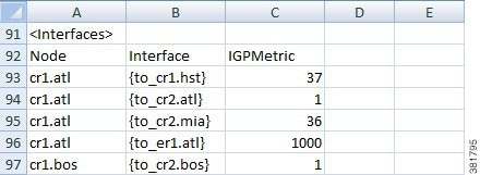
This example shows how to increase the IGP Metric for interfaces on core routers in the us_wan plan, which is in the $CARIDEN_HOME/samples directory. Figure 2-1 shows an excerpt from the original plan file. The Interfaces table has three columns: Node, Interface, and IGPMetric, which are all either “key” or “plan” columns. You only need the “key” values to uniquely define an interface.
Figure 2-1 Interfaces Table in us_wan.txt
In this simple example, you could manually update the IGPMetric column, using Excel or another text editor. To script the process, use CLI tools.
Step 1![]() Extract the Interfaces table from the plan file to a temporary file,
Extract the Interfaces table from the plan file to a temporary file, if-table.txt.
table_extract -plan-file us_wan.txt -out-file if-table.txt -tables Interfaces
Figure 2-2 Extracted Interfaces Table
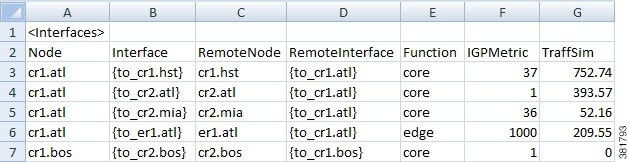
Figure 2-2 shows an excerpt from the extracted Interfaces table. The interesting part of the extracted table is that it contains more than just “key” and “plan” columns, it also has “derived” columns, which WAE Design creates when it reads a plan file or performs simulations. These extra columns make it is easier to identify the core routers in this example because there is now a Function column.
Step 2![]() The next step is to increase the IGP Metric for core router interfaces. The command below reads the extracted Interfaces file,
The next step is to increase the IGP Metric for core router interfaces. The command below reads the extracted Interfaces file, if-table.txt, finds the IGPMetric column of the Interfaces table, filters the rows to those with ‘core’ in the Function column, adds 100 to the IGPMetric in the filtered rows, and saves the result to a new file named if-table-edited.txt.
table_edit -plan-file if-table.txt -out-file if-table-edited.txt -table Interfaces -column IGPMetric -rowfilter "Function = 'core'" -value IGPMetric+100
Figure 2-3 Interfaces Table After Replacement
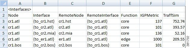
Figure 2-3 shows an excerpt from the updated file, if-table-edited.txt, which has the expected result in the IGPMetric column: the four core routers (nodes) shown have their IGP metrics increased by 100, and the edge router metric is unchanged.
Step 3![]() The last step is to update the original plan file, or to create a new one. In this case, the example command creates a new plan file, one that uses the.pln format. Changing the file format in this example shows the flexibility of the tools.
The last step is to update the original plan file, or to create a new one. In this case, the example command creates a new plan file, one that uses the.pln format. Changing the file format in this example shows the flexibility of the tools.
table_replace -table-file us_wan.txt -replace-table-file if-table-edited.txt -out-file us_wan.pln
Step 4![]() To verify the updates, open the
To verify the updates, open the us_wan.pln file. The GUI table contains the information shown in Figure 2-3.
Edit Plan File Tables Using the GUI
Although you can edit plan files in the WAE Design GUI, we recommend that you edit them in a text editor or spreadsheet so that you can easily make global changes. A spreadsheet, such as Excel, is useful because it clearly shows table columns in a tabular format.
Any time you make a change in the WAE Design GUI and save the plan file, you are, in effect, changing the tables in the plan. Additionally, you can choose Edit > Plan Tables as Database in the WAE Design GUI to view and edit tables directly in the plan file. In this dialog box, you can select one or more rows to modify attribute values in the columns. You can specify the desired selection from the Advanced Filter tab, by entering SQLite queries, and specify value changes in the Set Value tab, also using SQLite syntax.
Values defined in one table might be referenced in other tables. Be careful when changing a value that occurs in multiple places. For example, the Nodes table identifies the sites in which nodes reside. If you change a site name in the Sites table, you must also change it in the Nodes table and all other instances.

Step 1![]() Choose Edit > Plan Tables as Database. The Plan Table Database Editor opens, showing all possible tables in the left pane.
Choose Edit > Plan Tables as Database. The Plan Table Database Editor opens, showing all possible tables in the left pane.
Step 2![]() In the left pane, select the desired table. If the table already exists in the plan, it is displayed.
In the left pane, select the desired table. If the table already exists in the plan, it is displayed.
Step 3![]() Optional: Filter the table entries by using the Filter control menu or by entering text in the Search field (top right).
Optional: Filter the table entries by using the Filter control menu or by entering text in the Search field (top right).
Step 4![]() Click the field you want to change and then edit the information, or choose one of these more advanced editing options.
Click the field you want to change and then edit the information, or choose one of these more advanced editing options.
Step 5![]() Visually verify that the change is correct.
Visually verify that the change is correct.
Step 6![]() To open the new plan, click Open in WAE Design. To save the new plan without opening it, click Save as File.
To open the new plan, click Open in WAE Design. To save the new plan without opening it, click Save as File.
Error Handling When Opening Edited Plans
Because plan files can be edited directly by the user, errors must be handled when opening plan files. The default behavior for table errors is to log a warning and ignore any row of any table that is inconsistent with information already processed. For example, if the <Nodes> table lists two nodes with the same name (which is a key column) the second row is ignored.
To simplify user editing of.txt format plan files, WAE Design gracefully handles common problems encountered during the opening process. For example, although the simplest plan can contain nodes, interfaces, and circuits, there are certain situations in which only an <Interfaces> table need be specified.
WAE Design makes the following changes when opening a plan with missing or incomplete information:
- Omitted tables are assumed to be present with no entries.
- Key columns are required for each row in a table. Other columns can be entirely omitted, and default values are assumed for all their entries. The default values are listed in the Table Format Reference.
- Individual entries that are left blank (in non-key columns) are filled in with default values.
- Any nodes created in the Node column of the Interfaces table are created in the <Nodes> table if they do not already exist.
- The columns Remote Node and Remote Interface in the <Interfaces> table are derived columns, which are normally ignored when WAE Design opens a plan. However, in this case, when the Node, Interface, Remote Node, and Remote Interface unambiguously identify another interface as the remote interface for this circuit, and the two interfaces are not already defined as belonging to any circuit in the <Circuits> table, then a circuit connecting these two interfaces is created.
- In the <Nodes> table, if the site entry is blank, a new site is created for this node with the same name as the node. Sites referenced in the <Nodes> table are added to the <Sites> table if not already present.
- If Node and Interface in the <InterfaceTraffic> table are both blank, and the (derived) column IPAddress in the table contains a valid reference to an interface in the
<Interfaces>table, then (Node, Interface) for that interface is entered and the traffic is associated with that interface. This allows an <InterfaceTraffic> table to be added to the plan that references traffic measurements only by IP Address. - If Source in the <LSPTraffic> table is blank, and the (derived) column SourceIP contains a valid reference to a node, and this Node and the Name entry uniquely identify an LSP, then that node name is entered into the Source column and the traffic is associated with that LSP.
Tables as Command Arguments
Many CLI tools take arguments that require the specification of a set of plan objects. For example, merge_nodes takes a nodes-table parameter that specifies the list of nodes to merge. Such a list can be specified in a file containing a table in the WAE Design table format. Tables used as arguments must contain at least the key columns defined for that table for the tool to uniquely match the objects in the import table with the objects in the plan.
To create tables for use as command-line tools arguments, follow these steps:
Step 1![]() Extract the full table of objects from the plan that is the target of the command-line tool, using
Extract the full table of objects from the plan that is the target of the command-line tool, using table_extract.
Step 2![]() Use an editor to select the appropriate rows in the table, and delete the rest. Or, typically in a script, use
Use an editor to select the appropriate rows in the table, and delete the rest. Or, typically in a script, use mate_select to select the rows using SQL syntax.
LSP Mesh Creation Example
To create an LSP mesh between the core routers in sites ATL, MIA, and WDC of the us_wan.txt plan, you must first create a file that contains the list routers in the mesh. The following example extracts the Nodes table from the plan file, and then selects the desired core routers, and saves the result as lsp_nodes.txt.
Step 1![]() Extract the Nodes table from the plan file.
Extract the Nodes table from the plan file.
table_extract -plan-file us_wan.txt -out-file nodes-table.txt -tables Nodes
Step 2![]() Select the desired core routers and save the result as
Select the desired core routers and save the result as lsp_nodes.txt.
mate_select -table-file nodes-table.txt -out-file lsp_nodes.txt -table nodes -filter "(Site LIKE 'ATL' OR Site LIKE 'MIA' OR Site LIKE 'WDC') AND Name REGEXP '.*cr.*'" -show-columns Name

Note![]() The SQL query uses
The SQL query uses LIKE, rather than =, when selecting sites to avoid case-insensitivity problems.
The resulting lsp_nodes.txt file contains the following list of nodes:
<nodes>
Name
cr1.atl
cr1.mia
cr1.wdc
cr2.atl
cr2.mia
cr2.wdc
Step 3![]() Create the LSP mesh by invoking the
Create the LSP mesh by invoking the lsp_mesh_creator tool, specifying the lsp_nodes.txt file as a command-line argument.
lsp_mesh_creator -plan-file us_wan.pln -out-file us_wan_lsps.pln
-source-nodes-table lsp_nodes.txt -dest-equals-source true
SQL Queries in WAE Design
Three command-line tools in WAE Design use SQL syntax for filtering, summarizing, and manipulating plan files and reports.
-
mate_select—Filters tables in the reports. -
mate_summary—Summarizes tables in the reports, primarily to provide summary data for network visualization over time. -
mate_sql—An advanced SQL query tool.
WAE Design uses the SQLite implementation of the SQL language (see www.sqlite.org, especially www.sqlite.org/lang.html).
The following operators have special meaning in WAE Design:
REGEXP —Case-insensitive matching of regular expressions. For example, SQL expression
Is true for Name equal to 'CR', 'Cr' or 'CR01'. (But not for Name equal to 'er.cr')
MATCH —Some columns in the tables contain semicolon-delimited lists, for example a list of tags in the Tags column of the Nodes and Interfaces tables, or the list of interfaces in the Actual Path column of the LSP table. The MATCH operator tests for membership in these lists. For example,
Is true for Tags equal to 'Asia;Europe', 'EUROPE', and so on. The matching is case-insensitive.
The operator '=' is case-sensitive in SQL. The operator LIKE, which is case-insensitive, is often more useful for plan schema tables because the case is never relevant.
This function has the following syntax options:
–![]()
SUBNET(Column_Name, 'ip_address/prefixlen')
–![]()
SUBNET(Column_Name, 'ip_address/netmask')
–![]()
SUBNET(Column_Name, 'ip_address', 'prefixlen')
–![]()
SUBNET(Column_Name, 'ip_address', 'netmask')
The following examples demonstrate usage of each syntax:
–![]()
SUBNET(Column_Name, '192.168.1.0/24')
–![]()
SUBNET(Column_Name, '192.168.1.0/255.255.255.0')
–![]()
SUBNET(Column_Name, '192.168.1.0', '24')
–![]()
SUBNET(Column_Name, 'ip_address', '192.168.1.0, '255.255.255.0)
The following shows usage in a real SELECT statement:
select * from Table where subnet(IPAddress, '192.168.1.0/24');
This WHERE clause matches a row if the field IPAddress is an IP address in the 192.168.1.* network.
SQLite does not allow arbitrary functions to have infix notation, so the following notation is impossible:
Where IPAddress SUBNET '192.168.1.0/24'
Syntax: SUBSTITUTE(Column_Name, 'old', 'new')
where 'old' and 'new' are values like those used in the syntax: s/old/new
The following example shows how to replace the m with c in all node names that start with mr :
User-Defined Columns and Tables
You can add new tables of your own design and new columns to the standard tables. You might also choose to create columns for use in tools such as the RSVP-TE Optimization ( rsvp_te_opt) tool. Using these user-defined structures can help reduce the number of extra files required in a solution, and are helpful in custom scripts that need to carry information from one step to another.
Each user-defined table or column is prefixed with a namespace, which is a convenient way of grouping tables or grouping columns under one name to prevent conflicts with plan table names and plan columns.
WAE Design does not check user-defined columns and tables for errors. However, they are preserved on import and export, and their contents are displayed in the GUI and plan table hierarchy.
Create User-Defined Columns
Once a user-defined column is added to a plan table, you can manipulate it in the WAE Design GUI. You can duplicate it, delete it, or edit its value by right-clicking the table row and clicking the User tab. You can also modify or delete user-defined columns by choosing Edit > Plan Tables as Database.
Add Columns Using a Text Editor
Step 1![]() Open a plan file in a text editor.
Open a plan file in a text editor.
Step 2![]() Find the table to which you are adding the column.
Find the table to which you are adding the column.
Step 3![]() Add a tabbed space at the end of the headings and then enter the column name using the following format. Note that all columns must have a tabbed space between them.
Add a tabbed space at the end of the headings and then enter the column name using the following format. Note that all columns must have a tabbed space between them.
You can chain Namespaces together using :: between their names.
Namespace1::Namespace2::... ::ColumnName
Step 4![]() For each object to which you want to enter a value, tab to the user-defined column, and enter the value.
For each object to which you want to enter a value, tab to the user-defined column, and enter the value.
Example: Table 2-4 shows a user-defined column that was added to a <Sites> table. The first three columns are schema columns. The last is a user-defined column where the Namespace is Customer and the ColumnName is Service. Combined, they form the user-defined column named Customer::Service. The values Voice and Video were entered on their respective rows.
|
|
|
|
|
|---|---|---|---|
Add Columns Using the GUI
Step 1![]() Show the table in which you want to add the column.
Show the table in which you want to add the column.
Step 2![]() Do one of the following:
Do one of the following:
Step 3![]() In the dialog box that opens, click New ; a New User Property dialog box opens.
In the dialog box that opens, click New ; a New User Property dialog box opens.
a.![]() Enter the prefix, name, and select the type (text, real, integer, or boolean).
Enter the prefix, name, and select the type (text, real, integer, or boolean).
b.![]() If you are creating this column through the User tab, you can enter a value for the selected property.
If you are creating this column through the User tab, you can enter a value for the selected property.
Otherwise, to populate the column after adding it (after Step 4), you must open the Properties dialog box for the appropriate object and select the User tab to enter the value.
Create User-Defined Tables
Once a user-defined table is added, it is available in the WAE Design GUI and shows by default. Each user-defined table has a context menu containing Row Properties that lets you modify content directly from the table just like you would modify properties in plan tables. From this context menu, you can also delete or duplicate rows in tables. Duplications are exact, meaning, the duplicated rows do not contain objects that are renamed with the usual convention of [#].
Step 1![]() Open a plan file in a text editor.
Open a plan file in a text editor.
Step 2![]() On an empty row, enter the table name using the following format. You only need one Namespace, though you can chain them together using :: between their names.
On an empty row, enter the table name using the following format. You only need one Namespace, though you can chain them together using :: between their names.
<Namespace1::Namespace2::... ::TableName>
Note![]() Do not use plan table names as Namespaces. The TableName can be the same as a plan table name if it is used with a unique namespace. For example, Sites::Test is not a valid table, but Test::Sites is.
Do not use plan table names as Namespaces. The TableName can be the same as a plan table name if it is used with a unique namespace. For example, Sites::Test is not a valid table, but Test::Sites is.
Step 3![]() Complete the table by adding user-defined columns as described in Create User-Defined Columns.
Complete the table by adding user-defined columns as described in Create User-Defined Columns.
Example: Table 2-5 shows a new table that shows relationships between nodes and LSPs. The Namespace is LSP. The TableName is Relation. Combined, they form the user-defined table named <LSP::Relation>. (Note that singular “LSP” as a new namespace is permissible because the plan table name is the plural form “LSPs.”)
|
|
|
|
|---|---|---|
If you are going to create filter interactions that operate on object types, the objects must use the object notation defined in Table 2-1 . Table 2-6 shows an example in the Failure column. For information on creating object filters for user-defined tables, see Create Filter Interactions in Tables.
|
|
|
|
|---|---|---|
Change Column Appearance
To define the column appearance for both user-defined columns and user-defined tables, use the <ColumnData> table, which uses the columns described in Table 2-7 . Open a.txt file that is in a complete, tab-delimited format to see this table. Add one row per each user-defined column or table you are modifying.
Note that this table does not apply to plan columns in plan tables.
Example: Table 2-8 shows an example <ColumnData> table populated for the preceding two user-defined tables, and Figure 2-4 shows how they appear in the WAE Design GUI.
Table 2-8 Example: <ColumnData> Table
|
|
|
|
|
|
|
|
|---|---|---|---|---|---|---|
Figure 2-4 Example User-Defined Tables in WAE Design GUI
Create Filter Interactions in Tables
You can configure filter interactions for report tables and for user-defined tables by creating a <ReportTableInteractions> table and <UserTableInteractions> table, respectively. These tables are the same except for the Key columns.
- <ReportTableInteractions>—Defines the filter interactions between the report tables and the GUI. Report tables are available by choosing Window > Reports.
All tools that return tables have this behavior defined, though you can edit the interaction behavior. User-created reports, such as those returned by add-ons, do not have these interactions by default. Note also that not all tools return tables in their reports.
- <UserTableInteractions>—Defines the filter interactions between user-defined tables and plan tables. Without defining these interactions, while the user-defined tables are available, there is no interaction between the user-defined table and the rest of the plan file data. For information on creating tables, see User-Defined Columns and Tables.
The available filters are those that are already available from the plan file tables. For instance, in the L1 Nodes table, if you right-click an L1 node there are a number of contextual filters. If you were to create a filter interaction from a report table or user-defined table, and if that filter acted on L1 nodes, only those same L1 node filters would be available. You cannot further configure this filtering.
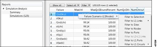
Figure 2-5 shows a Simulations table in a Simulation Analysis report filtering to L1 nodes. Note that since the Summary section of this report is not a table, no filtering interactions can be configured for it.
Figure 2-5 Simulations Table in Simulation Analysis Report Filtering to an L1 Node
<ReportTableInteractions> and <UserTableInteractions> are configured in the same manner, as defined in Table 2-9 , except for the Key columns.
|
|
|
|
|
|---|---|---|---|
Report name referenced in this entry. This must match the report named in the report output.
|
|||
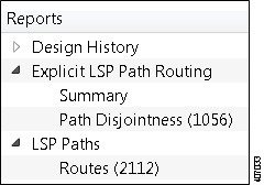
Report section name referenced in this entry. This must match the section named in the report output. Example: In the above two examples and figure, the viable Section names are Path Disjointness and Routes. The Summary section in the Explicit LSP Path Routing report is not tabular information and therefore, cannot be used. |
|||
User table name referenced in this entry. Example: If the user-defined table on which you are defining interactions is named <Object::Failures>, that is the name you would enter here. |
|||
Name that appears as the selection when you right-click a row within the report table or user-defined table. |
|||
Required if the ReferenceType is Table. Identifies the name of the plan table to which you want to filter. Do not use spaces in the name. Example: The <L1Links> table is entered as L1Links. This means if you click any item in this report table or user-defined table, the filter selection is the same as if you were in the <L1Links> table. |
|||
Required if the ReferenceType is Table. List of one or more comma-separated columns in the report table or user-defined table. Combined with the DestJoinColumns, this maps the selected row to the filtered table. There is a one-to-one, sequential mapping between the entries in each of these two columns. That is, the first entry for SourceJoinColumns maps to the first entry in the DestJoinColumn, the second entries map to each other, and so on until all entries are mapped. Therefore, the list must contain the same number of entries as DestJoinColumns. For a complete example, see Example: Filtering to Tables. Example: If the second SourceJoinColumns entry is Active, the filter maps the Active column in the report table or user-defined table to the second entry (column) identified in DestJoinColumns. |
|||
Required if the ReferenceType is Table. List of one or more comma-separated columns in the report table or user-defined table that identifies the column to use in the table from which you are filtering. The list must contain the same number of entries as SourceJoinColumns. For a complete example, see Example: Filtering to Tables. Example: If the DestJoinColumns entry is Traff Sim and the Table entry is Interfaces, the filter looks for the Traff Sim column in the <Interfaces> table. If this is the first entry in DestJoinColumns, it maps to the first entry in SourceJoinColumns. |
|||
Required if the ReferenceType is Object. Identifies the column name in the report table or user-defined table that specifies the object type on which to filter. The objects in this column must be in the object-notation format listed in Table 2-1 . For an example, see Example: Filtering to Objects. |
Example: Filtering to Tables
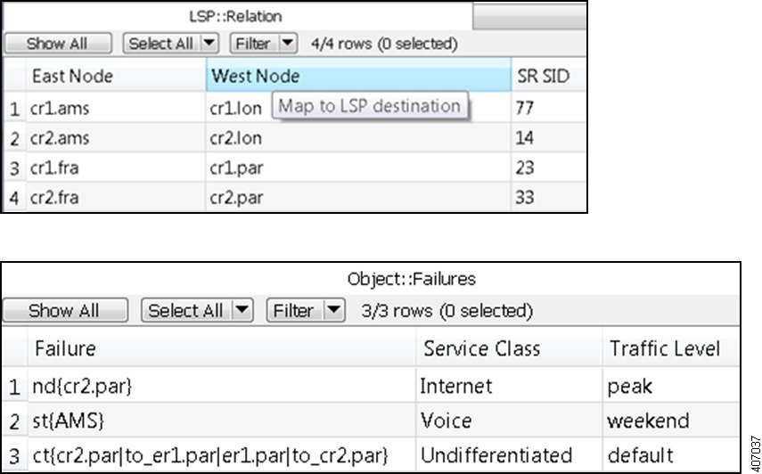
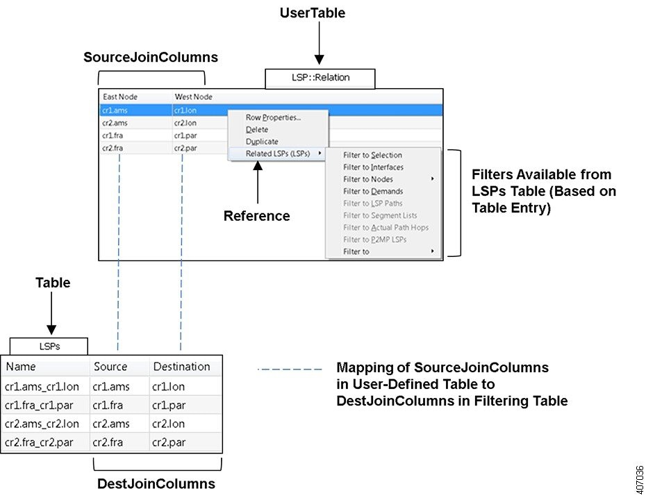
Table 2-5 shows a user-defined table named <LSP::Relation>. Notice that object definitions do not require object notation when using a ReferenceType of Table.
Table 2-10 shows a <UserTableInteractions> table that defines the following:
- UserTable defines a table interaction filter for the <LSP::Relation> table in the WAE Design GUI.
- ReferenceType is Table, so the filtering defined in this row explicitly references a plan table by name in the Table column.
- Reference defines that when you right-click a row in the <LSP::Relation> table, the context menu shows “Related LSPs.”
- Table defines that the filtering table is <LSPs>.
- To determine what to find in the <LSPs> table, the filter uses the SourceJoinColumns and DestJoinColumns to look for both of the following:
–![]() A node in the East Node column of the <LSP::Relation> table that is listed in the Source column of the <LSPs> table.
A node in the East Node column of the <LSP::Relation> table that is listed in the Source column of the <LSPs> table.
–![]() A node in the West Node column of the <LSP::Relation> table that is listed in the Destination column of the <LSPs> table.
A node in the West Node column of the <LSP::Relation> table that is listed in the Destination column of the <LSPs> table.
If an entry in the <LSPs> table satisfies both conditions, the contextual filters for LSPs is made available to the selection as shown in Figure 2-6.
Table 2-10 Example: <UserTableInteractions> Defining Two Table Filters
|
|
|
|
|
|
|
|
|---|---|---|---|---|---|---|
Figure 2-6 Example Table Filtering
Example: Filtering to Objects
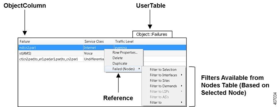
Table 2-6 shows a user-defined table named <Objects::Failures>. Note that the objects (a node, site, and circuit) listed in the Failure column use the object-notation format described in Table 2-1 .
Table 2-11 shows a <UserTableInteractions> table that defines the following:
- UserTable defines a table interaction filter for the <Objects::Failures> table in the WAE Design GUI.
- Reference defines that when you right-click a row in the <Objects::Failures> table, the context menu shows “Failed.”
- ReferenceType is Object, so the tables from which the selections filter differ depending on which object is selected.
- ObjectColumn defines the column used to identify the object on which to filter.
In Figure 2-7, if you right-clicked on the first row and selected Filter to Selection, you would go to the node named cr2.par in the Nodes table. If you selected any other filter, you would go to the same filter as if you had selected cr2.par from the Nodes table. For instance, if you selected Filter to Sites, you would go to the same site in the Sites tables as if you had selected cr2.par form the Nodes table and filtered to it.
Table 2-11 Example: <UserTableInteractions> Defining an Object Filter
|
|
|
|
|
|
|
|
|---|---|---|---|---|---|---|
Figure 2-7 Example Object Filtering
External Tables
In addition to plan tables, external tables provide input to plan files or are the result (output) of running tools on the plan file.
- Demand Mesh Table.
- Edits Table.
- Tables for importing traffic and traffic growth rates; see Importing Traffic and Growth Rates .
- Tables for exporting routes and explicit LSP path settings; see Exporting Routes .
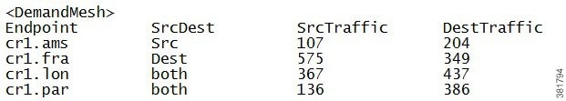
Demand Mesh Table
A <DemandMesh> table contains columns that identify the source and destination endpoints for a demand mesh, and optionally contains columns that specify the source and destination traffic for each (Figure 2-8).
- Endpoint—Represents the source/destination of a demand. For nodes, this corresponds to the node name. Other types of endpoints can also be specified. For example, 'AS{12345}' is a valid entry for an AS.
- SrcDest—Has a value of Src, Dest, or both, which specifies whether to use the endpoint as the source of the new demands, as the destination, or as both.
- SrcTraffic—Represents the source traffic (used by the dmd_traffic_creator tool).
- DestTraffic—Represents the destination traffic (used by the dmd_traffic_creator tool).
Figure 2-8 Example <DemandMesh> Table
Edits Table
The table_edit CLI tool can optionally use a file containing an <Edits> table, which is a very time-efficient means of globally modifying plan schema tables.
- Table—The name of the table to edit.
- Column—The name of the column in the table to edit. Must be one of the plan configuration columns, not derived/extended columns. If the column does not exist, it is created if the column is of the form Namespace::ColumnName.
- (RowFilter)—SQL WHERE statement selecting rows in the table. If empty, defaults to all. All columns, including derived and joined columns, are available for selection.
- Value—SQL Expression with value to insert in the column matching the filter selection. All columns, (including derived and joined columns, and including the column currently being edited, are available to use in this expression.
Example: This example shows an Edits file that change the forecast values in the demands table. The following tables show the original demands table, the edits table, and the updated demands table after running table_edit.
|
|
|
|
|---|---|---|
|
|
|
|
|
|---|---|---|---|
|
|
|
|
|---|---|---|
 Feedback