- Overview
- Plan Files and Patch Files
- User Interface
- Plan Objects
- Traffic Demand Modeling
- Simulation
- Simulation Analysis
- Forecasting Traffic
- IGP Simulation
- MPLS Simulation
- RSVP-TE Simulation
- Segment Routing Simulation
- Layer 1 Simulation
- Quality of Service Simulation
- BGP Simulation
- Advanced Routing with External Endpoints
- VPN Simulation
- Multicast Simulation
- Metric Optimization
- RSVP-TE LSP Optimization
- LSP Optimization
- SR-TE Optimization
- LSP Loadshare Optimization
- Changeover
- Reports
- Cost Modeling
- Plot Legend for Design Layouts
Cisco WAE Design 6.3.1 User Guide
Bias-Free Language
The documentation set for this product strives to use bias-free language. For the purposes of this documentation set, bias-free is defined as language that does not imply discrimination based on age, disability, gender, racial identity, ethnic identity, sexual orientation, socioeconomic status, and intersectionality. Exceptions may be present in the documentation due to language that is hardcoded in the user interfaces of the product software, language used based on RFP documentation, or language that is used by a referenced third-party product. Learn more about how Cisco is using Inclusive Language.
- Updated:
- January 7, 2016
Chapter: Segment Routing Simulation
Segment Routing Simulation
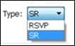
By default, WAE Design creates and routes RSVP LSPs. However, you can create Segment Routing (SR) LSPs1 by changing the LSP Type property to SR. These SR LSPs use autoroute, forwarding adjacencies, and class-based forwarding, just like RSVP LSPs. It is once the packet enters the tunnel that the different routing mechanisms determine the path. An RSVP LSP is first established along a path, with each node on the path accepting the reservation request and maintaining the reservation state. In contrast, SR LSPs rely on a segment list that is created at the LSP’s source node (head-end). This segment list, which is stored in the packet (demand), directs the traffic over a series of configured node segments and interface segments. SR LSPs use IP routing (and thus, potentially ECMP) between segments.
SR LSP Segment Types
The segment list of an SR LSP contains one or more node segments, interface segments, and/or anycast groups.
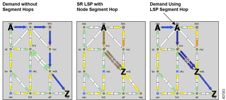
- Node segment—The SR LSP takes the shortest path to the specified node. Figure 12-1 shows an example SR LSP from cr2.kcy node to cr2.mia node using one segment node, which is cr2.okc. Since the IGP metrics are equal, the traffic is routed using ECMP to reach okc.

Note![]() The process of creating and optimizing segment lists and their segment list hops can be automated using the SR-TE Optimization tool. For information, see the SR-TE Optimization chapter.
The process of creating and optimizing segment lists and their segment list hops can be automated using the SR-TE Optimization tool. For information, see the SR-TE Optimization chapter.
- Interface segment—The SR LSP routes traffic over this interface. On routers, interface segments can only be used in segment lists if the previous segment is the node containing the interface, or if the interface is the egress of the source node. In WAE Design, there is no restriction that an interface segment is local. Meaning, there is no requirement that the segment list contain a preceding segment to the node containing the interface.
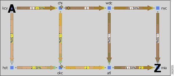
Figure 12-2 shows an example of an interface segment from cr2.chi to cr2.wdc. To ensure the path reaches cr2.chi (the node the packet must reach to use this interface segment), a node segment is configured first to reach chi. This figure also shows how a demand through an SR LSP reroutes when a node fails. The demand uses IGP to route around the failure and back to the segment, if possible.
- Anycast group segment—The SR LSP routes through the node in the anycast group that has the shortest path to it. In case of a tie between multiple nodes in an anycast group, ECMP is applied. This mechanism enables you to impose routing restrictions in terms of potential intermediate segment destinations. It also enables the SR LSP to choose among the possible next hops (next segment list hops), potentially reducing latency and improving load balancing.
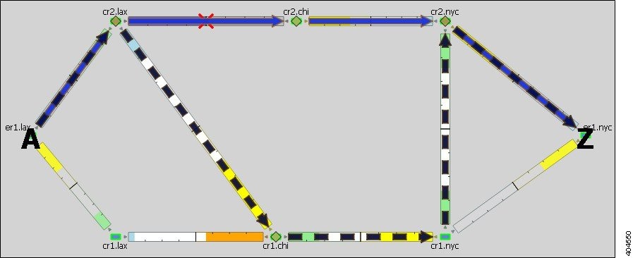
Figure 12-3 shows an example of anycast group nodes cr2.chi and cr1.chi. In one instance, the IGP metrics to those nodes have equal IGP metrics, so the SR LSP uses ECMP to route through both of them. When the IGP metric is increased from cr2.lax to cr1.chi, the SR LSP routes only through cr2.chi since it has the shortest path. However, as Figure 12-4 shows, if a failure prevents this shortest path from being used, the SR LSP can still route through the anycast group using the next-highest cost path.
To view a segment list, right-click the SR LSP’s source node to open the Properties dialog box, and then open the Segment tab. Alternatively, right-click an SR LSP and select Filter to Segment Lists. You can then right-click the segment list and select Filter to Segment List Hops, or double-click the segment list.
Figure 12-1 Example Node Segment
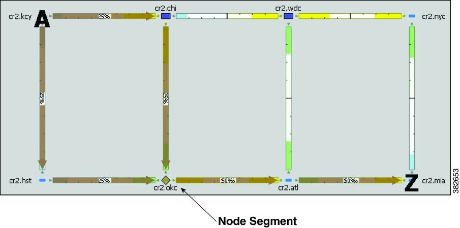
Figure 12-2 Example Interface Segment
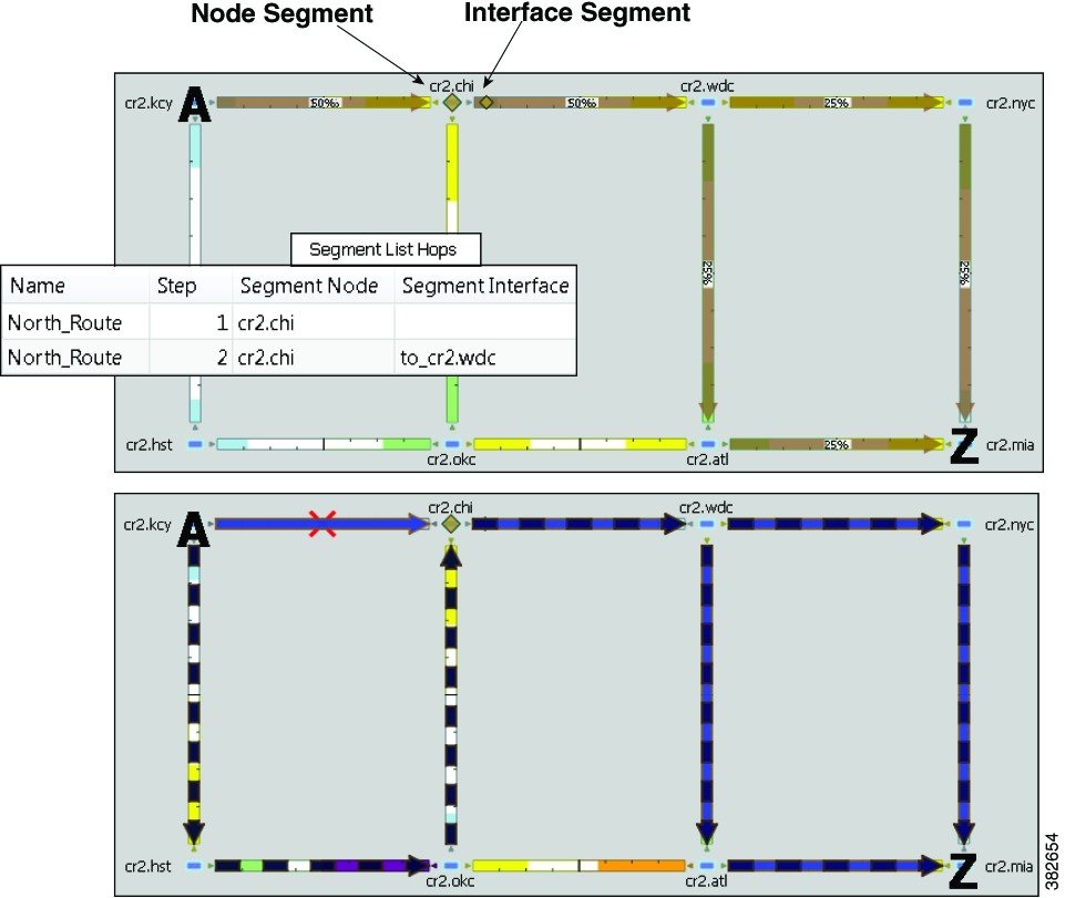
Figure 12-3 Example Anycast Group Segment
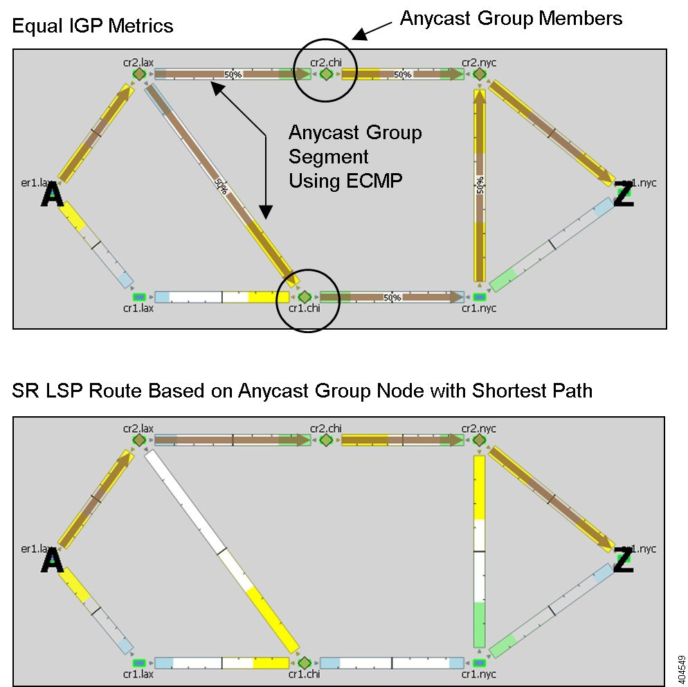
Figure 12-4 Example Anycast Group Segment Reroute Around Failure
SR LSP Paths
SR LSPs can have multiple LSP paths, where each LSP path has its own segment list. There is no distinction between standby and non-standby LSP paths for SR LSPs.
Note![]() If both the SR LSP and its SR LSP paths have segments, the segments on the LSP paths override those on the SR LSP.
If both the SR LSP and its SR LSP paths have segments, the segments on the LSP paths override those on the SR LSP.
Figure 12-5 shows an SR LSP from kcy to mia that has a primary and a secondary path. The primary path is configured with a chi node segment and chi-to-wdc interface segment, and the secondary path is configured with a node segment in okc. This can be seen by selecting the LSP paths individually from the LSP Paths table.
Figure 12-5 Example SR LSP Paths
SR LSP Routing
Assuming the common LSP mechanisms, such as autoroute and forwarding adjacencies have determined that a demand will enter an SR LSP, the LSP traffic is routed as follows. Note that if the destination node or any of the segments are not reachable, the SR LSP is not established.
Note![]() These descriptions are for the default behavior where SR LSPs take the shortest IGP path. Using the SR-TE LSP Optimization tool, you can optimize SR LSPs to use paths that are based on TE metrics or delays (latencies). You can also use this tool to avoid specified nodes. For information, see the SR-TE Optimization chapter.
These descriptions are for the default behavior where SR LSPs take the shortest IGP path. Using the SR-TE LSP Optimization tool, you can optimize SR LSPs to use paths that are based on TE metrics or delays (latencies). You can also use this tool to avoid specified nodes. For information, see the SR-TE Optimization chapter.
If the SR LSP has a segment list, the demand is routed using the segments within the segment list in the sequential order in which they appear.
If it is using an interface segment, the demand takes the shortest path of the source node of that interface, and then routes to that interface’s destination node.
If it is using an anycast group segment, the demand routes through the node with the shortest path. In case of a tie between multiple nodes in an anycast group, the SR LSP uses ECMP to route.
- If you select both a node segment and an anycast group segment when creating the segment list hop, the node segment has precedence.
- If the SR LSP contains LSP paths, then the demand is routed on the LSP path with the lowest path option for which the demand can be routed from source to destination. Demands for SR LSP paths route in the same manner as described above for SR LSPs.
- If the demand cannot be routed on the segments defined in the SR LSP or its LSP paths (for example, because of a failure in a node segment), the demand is routed to the destination using the IGP shortest path.
Note that if a hop (nodes, interfaces, anycast groups, or LSPs [demands only]) contains a segment ID (SID), the segment list hop inherits that SID. If necessary, you can edit this value in the object’s Properties dialog box.
Demands with Segment Lists
Demands can have segment lists, which is a way to model external control of SR LSP routes. For instance, data centers often push a segment list on to the traffic before it enters the modeled network. This can be represented by defining demands to have initial segment lists, thus configuring external control of the SR routes.
The demand segment lists contain the same segment hop types as SR LSPs: node, interface, and anycast groups. Additionally, demands can contain LSP segment hops, which enables you to model tunnel mapping. Using LSP segment hops, you can direct demands to use specific LSPs (SR or RSVP-TE). This enables external applications to choose route characteristics, such as latency and node avoidance.
Example: Figure 12-6 shows a demand without hops and how it is rerouted using an LSP segment hop.
Figure 12-6 Demand Route without and with LSP Segment Hop
Create SR LSPs and Their LSP Paths
SR LSPs and mesh SR LSPs are created the same way RSVP-TE LSPs are created. The difference is that you must set the Type property to SR. Once created, the next step is to either create the segment list or create LSP paths and their segment lists.
Likewise, LSP paths are created in the same way as RSVP-TE LSP paths. Since you are creating them from SR LSPs, the only editable properties are Path Option and Active.
For information on creating LSPs and LSP paths, see the MPLS Simulation chapter.
Create Segment Lists
Note![]() You create demand segment lists and LSP segment lists in exactly the same way. The difference being that demand segment lists can contain LSPs as segment hops.
You create demand segment lists and LSP segment lists in exactly the same way. The difference being that demand segment lists can contain LSPs as segment hops.
Step 1![]() In the LSP Properties dialog box, LSP path Properties dialog box, or demand Properties dialog box, click the Segments tab. Add the segments in the order in which they are to be followed.
In the LSP Properties dialog box, LSP path Properties dialog box, or demand Properties dialog box, click the Segments tab. Add the segments in the order in which they are to be followed.
- To add a new segment, select an existing segment (if applicable), and then click either the Insert Before or Insert After button to determine where the new segment goes sequentially. Go to step 2.
- To edit an existing segment, select it from the list and then select the Edit button. This opens the Edit Segment List dialog box. Go to step 2.
- To delete an existing segment, select it from the list, select the Delete button, and then press OK. You need not continue.
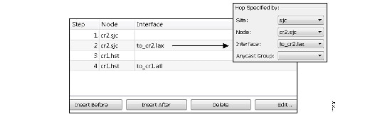
Step 2![]() To continue creating or editing a segment, use the following options and then click OK in the Edit Segment List dialog box. As needed, select the site, node, interface, or anycast group.
To continue creating or editing a segment, use the following options and then click OK in the Edit Segment List dialog box. As needed, select the site, node, interface, or anycast group.
Note![]() Interface segments must be the egress interface of a node segment.
Interface segments must be the egress interface of a node segment.
Once the segment list is created, another way to manage segments is to click one from the Segments List Hops table. From there you can change the site, node, and interface, though you cannot change the sequence.
Create Anycast Groups
Step 1![]() Follow one of these two steps to open the Anycast Group dialog box.
Follow one of these two steps to open the Anycast Group dialog box.
Step 2![]() Enter a unique name to identify the anycast group.
Enter a unique name to identify the anycast group.
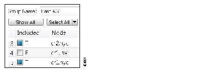
Step 3![]() For each node you want to include in or exclude from the anycast group, click the T (true) or F (false) check box, respectively. Then click OK.
For each node you want to include in or exclude from the anycast group, click the T (true) or F (false) check box, respectively. Then click OK.
Related Topics
- Traffic Demand Modeling chapter
- MPLS Simulation chapter
- SR-TE Optimization chapter
- LSP Loadshare Optimization chapter
 Feedback