Configure Devices Using Converged Access Deployment Templates for Campus and Branch Networks

What Are Converged Access Workflows?

The Converged Access workflow simplifies, automates and optimizes deployment of various enterprise-class next generation wireless deployment models for campus and branch networks. Cisco Prime Infrastructurecan automate the converged access deployment of wireless networks using converged access components such as Catalyst 3650, 3850, 4500 SUP 8-E switches, and Cisco 5760 Wireless LAN controller (WLC). The catalyst switches can be deployed as Mobility Agent (MA), Mobility Controller (MC), and Guest Anchor controller (GA).

The following figure illustrates the wireless converged access deployment mode.

Figure 1. Converged Access Workflow Overview


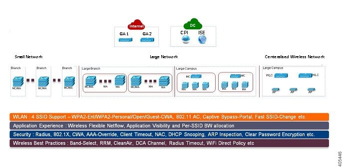
Single-Switch Small Network Deployment Model

This deployment model assumes single Catalyst 3650, 3850 or 4500 SUP 8-E switch deployed in Access layer in combined MA and MC roles. The Catalyst switches can be deployed in individual standalone system mode or in stackwise redundant supervisor mode.

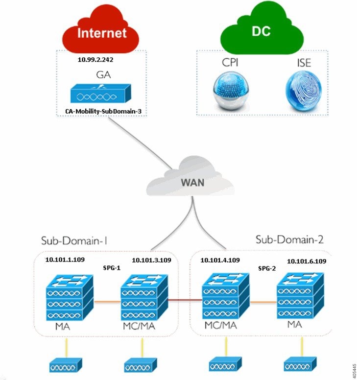
Controller-Less Single/Multi-Domain Deployment Model

This deployment model consists of multiple sub-domains and allows inter-domain MC peering for end-to-end seamless roaming across sub-domains. The MA switches are deployed in Access layer while the MC switches can be placed in Distribution layer.

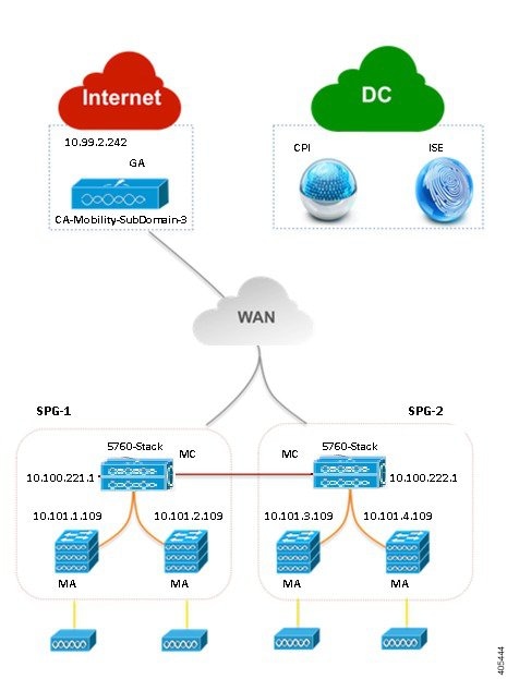
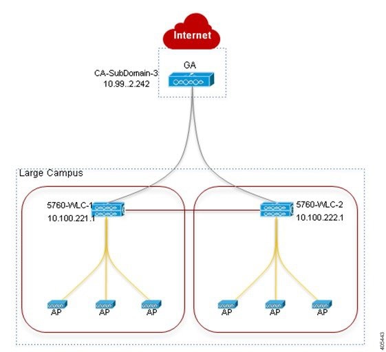
Controller-Based Single/Multi-Domain Deployment Model

A large scale converged access campus building is deployed with external 5760 WLC as MC. The Access layer switches are deployed as MA across multiple buildings with centralized 5760 MC. In such large network, multiple 5760 WLCs may co-exist for better load balancing and redundancy. Depending on the roaming requirement across different buildings, the inter-domain mobility peering between 5760 WLCs can be established.

Centralized Wireless Campus Deployment Model

In this deployment model, the switches in Access layer remain in traditional switching mode and wireless communication between Access Point (AP) and WLC is built as overlay network. In large scale campus deployments, multiple 5760 WLCs can be deployed for better load balancing and redundancy. To provide seamless large mobility domains, the inter-domain mobility peering 5760 WLCs can be established.

Key Benefits

  • Simple Automated Deployment—Simplifies the converged access deployment by automating the device configuration process. Requires only a few deployment specific inputs from the network administrator and pushes the complete converged access configurations to the network devices.
  • Error Free Deployment—The template-based configuration used by Cisco Prime Infrastructure avoids manual misconfigurations, making it easier to build/maintain enterprise-wide standardized configurations that are well understood by the network administrator.
  • Optimized Deployment—The configuration templates used by Cisco Prime Infrastructure incorporates a large number of Cisco best practice guidelines, improving the deployment quality. Some of the best practice wireless technologies/features that are automatically included in the template are Band-Select, Radio Resource Management (RRM), Fast SSID-Change, CleanAir, and Wireless QoS.
  • High Scalability—Supports large enterprises with thousands of branches. It not only reduces efforts to deploy greenfield branches, but also simplifies large scale conversion of traditional Ethernet based branch networks to converged access branches in an error-free way.

Supported Cisco IOS-XE Platforms

The following tables describe the supported Cisco IOS-XE platforms for small, large, and centralized network deployment models.

Table 1. Supported Cisco IOS-XE for Small Network Deployment Mode

Device Role

Cisco IOS-XE Platform

System Mode

Software Version

Mobility Agent/Mobility Controller (Single-Switch)

Catalyst 3650

Single or StackWise

3.6.0 and later

Catalyst 3850

Single or StackWise

3.6.0 and later

Catalyst 4500 SUP 8-E

Single or Dual-SUP

3.7.0 and later

Guest Anchor WLC

CT5760 WLC

Single or StackWise

3.6.0 and later

Table 2. Supported Cisco IOS-XE for Large Network Deployment Model

Device Role

Cisco IOS-XE Platform

System Mode

Software Version

Mobility Agent

Catalyst 3650

Single or StackWise

3.6.0 and later

Catalyst 3850

Single or StackWise

3.6.0 and later

Catalyst 4500 SUP 8-E

Single or Dual-SUP

3.7.0 and later

Mobility Controller

Catalyst 3650

Single or StackWise

3.6.0 and later

Catalyst 3850

Single or StackWise

3.6.0 and later

Catalyst 4500 SUP 8-E

Single or Dual-SUP

3.7.0 and later

CT5760 WLC

Single or StackWise

3.6.0 and later

Guest Anchor Controller

CT5760 WLC

Single or StackWise

3.6.0 and later

Table 3. Supported Cisco IOS-XE for Centralized Wireless Deployment Mode

Device Role

Cisco IOS-XE Platform

System Mode

Software Version

Mobility Controller

CT5760 WLC

Single or StackWise

3.6.0 and later

Guest Anchor WLC

CT5760 WLC

Single or StackWise

3.6.0 and later

Prerequisites for Converged Access Deployment

To successfully deploy the Converged Access solution using the Converged Access Workflow, the wired infrastructure of the network should be set for further configuration required for converged access. This section describes the prerequisite configurations for Converged Access Workflow based deployment.

You can view the prerequisites using the click here link in the Before you Begin page in the Converged Access Workflow ( Services > Network Services > Converged Access).

Prerequisites for Layer 2 and Layer 3

The following table describes the Layer 2 and Layer 3 prerequisites, and sample configuration for the Converged Access Workflow. In the sample configuration, the following nomenclature is used to represent the various wireless management VLANs in the MA and MC.

  • WM_VLAN - Name of the Wireless Management VLAN
  • WM_VLAN_id - ID of the Wireless Management VLAN
  • WLAN1_Client_VLAN_Name - VLAN name of WLAN 1
  • WLAN2_Client_VLAN_Name - VLAN name of WLAN 2
  • WLAN3_Client_VLAN_Name - VLAN name of WLAN 3
  • WLAN1_Client_VLAN_id - VLAN ID of WLAN 1
  • WLAN2_Client_VLAN_id - VLAN ID of WLAN 2
  • WLAN3_Client_VLAN_id - VLAN ID of WLAN 3

Note


WLANx_Client_VLAN_id represents all the three client VLAN Ids.
Table 4. Layer 2 and Layer 3 Prerequisites for Converged Access Switches for Device Roles MA and MC

Task on Converged Access Switch

Sample Configuration

Wireless Management VLAN

  • Create wireless management VLAN with a network wide unique name.
  • Configure access ports connected to APs under this VLAN.

! Mgmt VLAN on Access Switch 
vlan <WM_VLAN_id>
name <WM_VLAN>
! Apply VLAN to access ports connected to Access Points
interface GigabitEthernet 1/0/x
description Connected to Access-Points
switchport mode access
switchport access vlan <WM_VLAN_id>

Create Wireless Client VLANs

  • Create wireless client VLANs in VLAN database. The VLAN names are common across campus and branches.

! Create the wireless Client VLANs on Access Switch
vlan <WLAN1_Client_VLAN_id>
name <WLAN1_Client_VLAN_Name>        
vlan <WLAN2_Client_VLAN_id>
name <WLAN2_Client_VLAN_Name>        
vlan <WLAN3_Client_VLAN_id>
name <WLAN3_Client_VLAN_Name> 

DHCP Snooping /ARP Inspection

  • Enable DHCP snooping and ARP inspection on each WLAN client VLANs in the access switch (for static or dynamic VLAN).
  • Configure upstream Layer 2 trunk as trusted for ARP inspection and DHCP snooping.

! Enable DHCP Snooping & ARP Inspection on all WLAN 
! Client VLANs (Static or Dynamic)
ip dhcp snooping
ip dhcp snooping vlan name 
<WLANx_Client_VLAN_id>
no ip dhcp snooping information option
ip arp inspection vlan <WLANx_Client_VLAN_id>
ip arp inspection validate source destination allow-zeros
interface Port-Channel <id>
description L2 Trunk to Upstream Router/Switch
ip dhcp snooping trust
ip arp inspection trust

Switch Trunk Ports

  • Configure trunk ports to the WAN router(s). The trunk must allow WM_VLAN and the Client VLANs, and must be a trusted port for DHCP snooping or ARP inspection.
  • Ensure that the other ends of the trunk ports are properly configured (not shown).

! Configure trunk port to other connected switches/router
interface Port-channel1
description Connected to Upstream System
switchport trunk allowed vlan add <WM_VLAN_id>, <WLAN1_Client_VLAN_id>,<WLAN2_Client_VLAN_id>, <WLAN3_Client_VLAN_id>,
ip arp inspection trust
ip dhcp snooping trust

Default Gateway

  • Ensure that default gateway is configured.

! Configure default-gateway
<ip default-gateway
>

Wireless Mobility Controller

  • If you want Catalyst 3650, 3850, and 4500 SUP 8-E switches to be deployed as MC then configure the switches as MC, and reload them to make the configuration effective.

wireless mobility controller
write memory
reload

AP Licenses

  • MC must have sufficient AP licenses to support all APs in its sub-domain, and activate the licenses on the APs. The activation does not require a reboot.
  • The GA does not require AP license.

! Activate AP license on branch converged access switch
license right-to-use activate ap-count <count> slot <ID> acceptEULA

Security

  • Convert relevant authentication commands on the access switches to their Class-Based Policy Language (CPL) equivalents.

authentication convert-to new-style

This command permanently converts the legacy configuration on the switch to identity-based networking services. On entering this command, a message is displayed for your permission to continue. Permit the conversion.

Update AP Interface Template

  • Add wireless management VLAN to the AP interface template LAP_INTERFACE_TEMPLATE.
  • Apply the updated template to each switch port connected to an AP.
  • Verify that the VLANs are applied using the following command:

show derived-config interface <interface id
>

This step is not necessary if autoconf enable command is globally configured. In this case, the switch automatically detects the device types of the connected devices, and applies appropriate interface templates.


template LAP_INTERFACE_TEMPLATE
switchport access vlan <Wireless_Mgmt_VLAN_id>
! Associate the LAP_INTERFACE_TEMPLATE to switch 
! ports connected to APs. This puts the interface
! in shutdown state; so issue a “no shut” command
interface Gig 1/0/x
source template LAP_INTERFACE_TEMPLATE
no shutdown

The following describes the Layer 2 and Layer 3 prerequisites, and sample configuration for GA. In the sample configuration, the following nomenclature is used to represent the wireless management VLAN and Guest VLAN details for GA:

  • WM_VLAN - Name of the Wireless Management VLAN
  • WM_VLAN_id - ID of the Wireless Management VLAN
  • GUEST_VLAN_Name - VLAN name of Guest Anchor Controller
  • GUEST_VLAN_id - VLAN ID of Guest Anchor Controller
Table 5. Layer 2 and Layer 3 Prerequisites for Guest Anchor Controller

Task on Guest Anchor Controller

Sample Configuration for Guest Access Controller

Wireless Management VLAN

  • Create wireless management VLAN with a network wide unique name.

! Mgmt VLAN on Access Switch 
vlan <WM_VLAN_id>
name <WM_VLAN>

Create Wireless Guest VLAN

  • Create wireless Guest VLANs in VLAN database. The VLAN name must be common across all GAs.

! Create the wireless guest VLANS on Access Switch
vlan <GUEST_VLAN_id>
name <GUEST_VLAN_Name> 

DHCP Snooping / ARP Inspection

  • Enable DHCP snooping and ARP inspection on the Guest VLAN.
  • Configure Layer 2 trunk connected to the network as trusted for ARP inspection and DHCP snooping.

! Enable DHCP Snooping & ARP Inspection on Guest 
! VLAN
ip dhcp snooping
ip dhcp snooping vlan name <GUEST_VLAN_Name>
no ip dhcp snooping information option
ip arp inspection vlan <GUEST_VLAN_id>
ip arp inspection validate source destination allow-zeros
interface Port-Channel <id>
description L2 Trunk to network
ip dhcp snooping trust
ip arp inspection trust

Default Gateway

  • Ensure that default gateway is configured.

ip default-gateway <ip address>

Security

  • Convert relevant authentication commands on the access switches to their Class-Based Policy Language (CPL) equivalents.

authentication convert-to new-style

This command permanently converts the legacy configuration on the switch to identity-based networking services. On entering this command, a message is displayed for your permission to continue. Permit the conversion.

Prerequisites for Server Configuration

  • Cisco Prime Infrastructure
    • All network-wide catalyst switches and 5760 WLCs must be configured with SNMP.
    • The Converged Access switches must be added to the inventory of Cisco Prime Infrastructure . You need to provide SNMP and Telnet credentials to add the devices to the inventory.
    • Link Cisco Prime Infrastructure with Cisco ISE engine as external server to centrally monitor end-to-end client connectivity and policy enforcement details.
  • Cisco ISE/ACS
    • All network devices including catalyst switches and Guest Anchor WLC must be configured in Cisco ISE/ACS to enable centralized policy engine function.
    • AAA configuration is not required for converged access on individual network devices as it is automatically generated by Converged Access Workflow.
  • DHCP Server—Internal or external DHCP server must be preconfigured with appropriate pool settings for wireless clients.
  • DNS Server—Must be preconfigured with appropriate name-lookup process to successfully connect to the network.

Configure Devices Using Converged Access Templates

Prime Infrastructure uses different templates for different deployment models. You need to select the appropriate template-based on your network topology as explained in the following table:

Network Topology

Configuration Template

Single-switch small network

IOS-XE Controller - Small Network

Controller-less single/multi-domain branch

IOS-XE Controller - Large Network

Controller-based single/multi-domain branch

IOS-XE Controller - Large Network

Centralized wireless campus

IOS-XE Centralized Wireless Network

To deploy a converged access template:

Procedure


Step 1

Choose Services > Converged Access.

Step 2

Click Next to choose the deployment model.

Step 3

From the Select Deployment Model drop-down list, choose any one of the following options:

  • IOS-XE Controller - Small Network

  • IOS-XE Controller - Large Network

  • IOS-XE Centralized Wireless Network

Step 4

Click Next to choose the devices to be deployed.

Step 5

Choose the devices and click Next to apply the selected network configuration.

The selected device will be listed out in the left pane, and in the right pane you can configure the templates by entering the values for the Wireless Management, WLANs, Guest WLAN, Mobility, Security, Application Visibility and Control (AVC), and Quality of Services (QoS).

Step 6

Choose the devices individually and enter the Wireless Management configuration values.

Step 7

Click Apply and then Next.

Step 8

Enter the WLANs configuration values that are common to all the selected devices.

By default, the All Selected Devices check box is enabled. You can enter the WLAN configuration values for all the devices at the same time.

Step 9

Click Applyand then Next.

Step 10

(Optional) Enter the Radio configuration values that are common to all the selected devices. By default, the All Selected Devices check box is enabled.

Step 11

Click Applyand then Next.

Step 12

(Optional) Enter the Guest WLAN configuration values that are common to all the selected devices.

By default, the All Selected Devices check box is enabled.

Step 13

Click Apply.

Step 14

Choose the devices individually and enter the Guest Controller configuration values.

Step 15

Click Apply and then Next.

Step 16

Select the individual devices and enter the Mobility configuration values. The Mobility configuration fields will be available in the Converged Access Wizard only for large and centralized network deployments.

Step 17

Click Applyand then Next.

Step 18

(Optional) Enter the Security configuration values that are common to all the selected devices. By default, the All Selected Devices check box is enabled.

Step 19

Click Apply and then Next.

Step 20

(Optional) Enter the AVC and QoS configuration values that are common to all the selected devices. By default, the All Selected Devices check box is enabled.

Step 21

Click Apply and then Next to view the confirmation screen.

The confirmation screen allows you to view the device configuration information before deployment.

Step 22

(Optional) Enter the job name and click the Date radio button to schedule the deployment job.

Step 23

Click Deploy.


Guidelines for Entering Configuration Values

This section provides the field descriptions for converged access template and guidelines for entering the global and local configuration values for the following deployment models with specific examples.

  • Controller-less single-switch deployment model
  • Controller-less single/multi-domain deployment model
  • Controller-based single/multi-domain deployment model
  • Centralized wireless campus deployment model

Field Reference: Converged Access Templates

This section contains the field descriptions for converged access template.
Table 6. Wireless Management Field Descriptions

Field Name

Description

VLAN ID

VLAN ID of the selected device.

IP Address

Wireless management IP of the selected device.

Subnet mask

Subnet mask allocated to the selected device.

Table 7. WLAN Field Descriptions

Field

Description

SSID

Name of the wireless LAN.

ID

Wireless LAN ID. If SSID > 16, you need to manually enter the AP group name.

Security

Allows you to customize the login window for configuring an external web server such as ISE. The following security options are available for WLAN:

  • WPA2-Enterprise
  • WPA2-Personal
  • OPEN

For Guest WLAN, WebAuth (external) option alone is available.

Pre-Shred Key

This is a mandatory field, if you have a selected WPA2-Personal.The value must be alphanumeric and at least eight characters long.

Client VLAN Name

Name of the client VLAN. Can be alphanumeric.

AP Group

AP Group name is used to assign group name for the APs associated with WLAN and Client VLAN.

DHCP Required

This is an optional field. Check the DHCP Required check box for WLAN. This forces the wireless clients to use DHCP to get IP addresses. Clients with static address cannot access the network.

Radio

Radio bands used by WLAN.

Device Classification

You can turn on/off the device classification on the switch, using OUI and DHCP.

Device Profiling

You can turn on/off the device profiling. The following two options are available for device profiling:

  • Local profiling based on HTTP attributes
  • Radius profiling based on HTTP attributes

Client Exclusion

Turns on/off the client exclusion for the WLAN. When it is turned on, the misbehaving clients are added in an exclusion list so that they cannot access the network until the timeout is over. Clients may be added in the exclusion list due to excessive authentication attempts and using IP address of another client.

Client Exclusion Timeout (sec)

The timeout period for excluded clients.

Session Timeout (sec)

The timeout period for a client session. The client is re-authenticated before this period is over.

Table 8. Wireless Radio Field Descriptions

Field

Description

RF Group Name

Name of the RF group. Multiple MCs can be placed under a single RF group, to perform RRM in a globally optimized manner and perform network calculations on a per-radio basis.

Radio 2 GHz

This is an optional check box.

Radio 5 GHz

This check box is checked by default and it’s mandatory. You cannot uncheck this check box.

Disable Rates

These data rates are disabled. Clients cannot use these data rates to connect to access points.

Mandatory Rates

Clients must support these data rates in order to associate to an access point, although it may connect to the AP using one of the supported data rates.

Supported Rates

Clients that support this data rate may communicate with the access using the supported date rate. However, clients are not required to use this data rate in order to associate with the AP.

Country Code

Country code enables you to specify a particular country of operation. Configuring a country code ensures that each radio’s broadcast frequency bands, interfaces, channels, and transmit power levels are compliant with country-specific regulation.

Table 9. Guest Services Field Descriptions

Field

Description

Anchor Controller IP

Wireless management IP of Guest Anchor device.

Anchor Group Name

Group name of Anchor device.

Foreign Controller

Wireless management IP of MC to which the Guest Anchor device is associated.

Table 10. Security Field Descriptions

Field

Description

Radius Server (IPs)

IP address of the Remote Authentication Dial In User Service (RADIUS) server.

Key

Password of Radius server.

Device HTTP TACACS Authentication

Select this in order to enable TACACS based device authentication to access the converged access device.

TACACS+ Server IP(s)

IP address of the TACACS server.

Key

Password of the TACACS server.

Table 11. Application Services Field Descriptions

Field Name

Description

Netflow Collectors (IP:Port)

IP—The IP address of the Prime Infrastructure server.

Port—The port on which the NetFlow monitor will receive the exported data. For Prime Infrastructure the default port is 9991.

Example: 172.20.114.251:9991

WLAN-1 SSID Bandwidth(%)

Specify the maximum bandwidth percentage allowed for first WLAN.

WLAN-2 SSID Bandwidth(%)

Specify the maximum bandwidth percentage allowed for second WLAN.

WLAN-3 SSID Bandwidth(%)

Specify the maximum bandwidth percentage allowed for third WLAN.

Guest SSID Bandwidth(%)

Specify the maximum bandwidth percentage allowed for Guest WLAN.

Table 12. Wireless Mobility Field Descriptions

Field Name

Description

Role

Mobility Controller or Mobility Agent.

Controller IP

Wireless Management IP of Controller device.

Switch Peer Group Name

Peer group name in which the Agent is added.

Mobility Agent IP(s)

Wireless management IP of Mobility Agent devices. If you are entering more than one IP addresses, use semicolon to separate the IP addresses.

Peer Controller IP(s)

Wireless Management IP of peer controller device. If you are entering more than one IP addresses, use semicolon to separate the IP addresses.

Example: Controller-Less Single-Switch Network

A small-sized remote branch office or retail store may consists of a single converged access switch (standalone or stack) to provide network connectivity to the wired and wireless users.

For such network designs, the switch integrates both MC and MA functions. These networks may need guest wireless services, as well as common security and network access policy enforcement across all deployed sites.

The network administrator can use Prime Infrastructure IOS-XE Controller Small Network template to deploy converged access. The following figure 405448 illustrates the reference network for single-switch small network that shows three branch offices. Each site can be independently deployed using the workflow. Alternatively, one deployment workflow can deploy multiple sites. Prime Infrastructure allows you to configure the devices in five WLANs. The following figure illustrates three WLAN configuration scenario in the single-switch small network topology.

Figure 2. Controller-less Single-switch Small Network Model


You must enter the Wireless Management configuration values separately for each device. The following tablw describes the Wireless Management configuration values for MA/MC (10.100.1.109) and Guest Anchor (10.99.2.242) in the single-switch small network topology shown in above figure.

Table 13. Sample Wireless Management Configuration Values for MA/MC (10.100.1.109) and GA (10.99.2.242)

Data Field

MA/MC

GA

VLAN ID

155

33

IP

10.101.1.109

10.99.2.242

Subnet Mask

255.255.255.240

255.255.255.240

After applying the Wireless Management configuration values, you must enter at least one WLAN configuration values. The following table describes sample configuration of three WLANs for the single-switch small network topology shown in the above figure.

Table 14. Sample WLAN Configuration Values for MC/MA and GA

Data Field

WLAN 1

WLAN 2

WLAN 3

SSID

ABCCorp_802.1x

ABCCorp_PSK

ABCCorp_OPEN

ID

1

2

3

Security

WPA2-Enterprise

WPA2-Personal

OPEN

Pre-Shared Key

CISCO123

Client VLAN Name

8021X-WiFi_VLAN

PSK-WiFi_VLAN

OPEN_WiFi_VLAN

AP Group

Ap-group-1

Ap-group-HR

DHCP

Yes (Check the DHCP check box)

Radio

All

802.11g

802.11a/g

Device Classification

Yes (Check the Device Classification check box)

Device Profiling

None

Local

Both

Client Exclusion

Yes (check the Client Exclusion check box)

Yes (check the Client Exclusion check box)

Yes (check the Client Exclusion check box)

Timeout (sec)

60

100

100

Session Timeout (sec)

1800

2000

300

After applying the WLAN configuration values, enter the Wireless Radio configuration values for all the devices at the same time. The following table shows the Wireless Radio configuration values for MC/MA and GA in the single-switch small network topology shown in the above figure.

Table 15. Sample Wireless Radio Configuration Values for MC/MA and GA

Data Field

Sample Configuration Value

RF Group Name

CA-RF

Radio 5 GHz

Yes (This check box is checked by default and it’s mandatory. You cannot uncheck this check box.)

Disable Rates

RATE_6M;RATE_18M; RATE_54M

Mandatory Rates

RATE_6M;RATE_18M; RATE_54M

Supported Rates

RATE_6M;RATE_18M; RATE_54M

Radio 2 GHz

No (This is an optional check box)

Disable Rates

Mandatory Rates

Supported Rates

Country Code

UNITED STATES

After applying the Wireless Radio configuration values, enter the Guest Services configuration values for all the devices at the same time. The following table describes the Guest WLAN configuration values for all the devices in the single-switch small network topology shown in the above figure.

Table 16. Sample Guest WLAN Configuration Values for MC/MA and GA

Data Field

Sample Configuration Values

SSID

ABCCorp_Guest

ID

15

Security

WebAuth-External

Pre-Shared Key

Client VLAN Name

Guest_WiFi_VLAN

AP Group

AP-group-guest

DHCP

yes (check the DHCP check box)

Radio

802.11a (or 802.11a/g, 802.11b/g, 802.11g, or All)

Device Classification

Yes (check the Device Classification check box)

Device Profiling

Both

Client Exclusion

ON

Timeout (sec)

100

Session Timeout (sec)

5000

The following table describes the sample Guest Controller configuration values for MC/MA (10.100.1.109) and GA in the single-switch small network topology shown in the above figure.

Table 17. Sample Guest Controller Configuration Values for MC/MA (10.100.1.109) and GA

Data Field

MC/MA

GA

Anchor Controller IP

10.99.2.242; 10.99.2.243

10.99.2.242; 10.99.2.243

Anchor Group Name

CA-Mobility-SubDomain-3

CA-Mobility-SubDomain-3

Foreign Controllers

10.101.4.109

10.101.1. 109; 10.101.4.109; 10.101.7.109

After applying the Guest Services configuration values, enter the Security configuration values for all the devices at the same time. The following table describes the sample Security configuration values for MC/MA and GA in the single-switch small network topology shown in the above figure.

Table 18. Sample Security Configuration values for MC/MA and GA

Data Field

Sample Configuration Values

Radius Server (IPs)

10.100.1.49

Key

CISCO

Device HTTP TACACS Authentication

Yes (check the Device HTTP TACACS Authentication check box)

TACACS+ Server IP(s)

10.100.1.51

Key

cisco

After applying the Security configurations values, enter the AVC and QoS configuration values for all the devices. The following table describes the sample configuration values for MC/MA and GA in the single-switch small network topology shown in the above figure.

Table 19. Sample AVC and QoS Configuration Values for MC/MA and GA

Data Field

Sample Configuration Values

Netflow Collectors (IP:Port)

10.100.1.02:9991; 10.100.1.03:2055

WLAN-1 SSID Bandwidth(%)

40

WLAN-2 SSID Bandwidth(%)

30

WLAN-3 SSID Bandwidth(%)

20

Guest SSID Bandwidth(%)

10

Example: Controller-Less Single/Multi-Domain Wireless Network

The following figure illustrates the controller-less deployment model that leverages Catalyst switches for MA and MC roles without depending on an external WLC. This converged access deployment model is suitable for large branches and campus, and can be implemented using Prime Infrastructure IOS-XE Controller Large Network template.

Figure 3. Controller-Less Large Branch Network Model


Enter the Wireless Management, WLANs, Wireless Radio, and Guest WLAN configuration values for all the devices as described in single-switch small network deployment model. Enter the Guest Controller configuration values and Mobility configuration values for MA, MC, and GA for the topology shown in the above figure.

Table 20. Sample Guest Controller Configuration Values for MA, MC, and GA

Data Field

MA

MC

GA

Anchor Controller IP

10.99.2.242

10.99.2.242

10.99.2.242

Anchor Group Name

CA-Mobility-SubDomain-3

CA-Mobility-SubDomain-3

CA-Mobility-SubDomain-3

Foreign Controller

10.101.4.109

10.101.3.109

10.101.3.109

The following table describes the Mobility configuration values for MA, MC in SPG-1, and GA shown in the above figure.

Table 21. Sample Mobility Configuration Values for MA, MC, and GA

Data Field

MA

MC

GA

Role

Agent

Controller

Controller

Controller IP

10.101.3.109

10.101.3.109

Switch Peer Group Name

SPG-1

SPG-1

Mobility Agent IP(s)

10.101.1.109

Peer Controller IP(s)

10.101.4.109

Repeat the same procedure for MA and MC in SPG-2 as shown in the above figure.

After applying the Mobility configuration values, enter the Security, AVC and QoS configuration values as described in single-switch small network deployment model.

Example: Controller-Based Single/Multi-Domain Wireless Network

The following figure illustrates the controller-based single/multi-domain deployment model that leverages the same IOS-XE Controller Large Network template for deploying converged access with an external 5760 WLC as the MC.

Figure 4. Controller-Based Large Campus Model


Enter the configuration values as explained in controller-less single/multi-domain wireless deployment model.

Example: Centralized Wireless Campus

Prime Infrastructure IOS-XE Centralized Wireless template supports traditional wireless deployment model using next-generation 5760-WLC. In this model, any generation Access layer switches are deployed in traditional Ethernet switch mode over which WLC and the APs build an overlay network using CAPWAP Tunneling mechanism.

The following figure illustrates 5760-WLC based Centralized Wireless deployment using IOS-XE Centralized template.

Figure 5. Centralized Campus Network Model


Enter the Wireless Management, WLANs, Wireless Radio, and Guest WLAN configuration values for all the devices as described in single-switch small network deployment model. Enter the Guest Controller configuration values and Mobility configuration values for 5760 WLC in SPG-1 and GA for the topology shown in the above figure.

Table 22. Sample Guest Controller Configuration Values for 5760 WLC and GA

Data Field

5760 WLC

GA

Anchor Controller IP

10.99.2.242

10.99.2.242

Anchor Group Name

CA-Mobility-SubDomain-3

CA-Mobility-SubDomain-3

Foreign Controllers

10.100.222.1

10.100.221.1; 10.100.222.1

Table 23. Sample Mobility Configuration Values for 5760 WLC and GA

Data Field

5760 WLC

GA

Peer Controller IP(s)

10.100.222.1

Repeat the same procedure for 5760 WLC in SPG-2 shown in the above figure. After applying the Mobility configuration values, enter the Security, AVC and QoS configuration values as described in single-switch small network deployment model.