- Overview to Cisco NFVI
- Cisco NFVI Installation Overview
- Preparing for Installation on Servers Without Internet Access
- Preparing for Cisco NFVI Installation
- Installing Cisco VTS
- Installing Cisco VIM
- Installing Cisco VIM Insight
- Installing Cisco VIM through Cisco VIM Insight
- Verifying the Cisco NFVI Installation
- Overview to Cisco NFV Infrastructure
- Overview to Cisco Virtual Infrastructure Manager
- Cisco NFVI Networking Overview
- UCS C-Series Network Topologies
- Cisco VIM Management Node Networking
- IPv6 Support on Management Network
- UCS C-Series and B-Series Topologies
- Cisco NFVI High Availability
- Cisco NFVI Storage Node Overview
- Overview to Cisco Virtual Topology System
- Overview to Cisco NFVIMON
- Overview to Cisco VIM Insight
- Overview to NFVBench
- Overview to ACI Plugin Integration
- Disk Management in VIM 2.2
- OSD Maintenance
Overview to Cisco NFVI
This section contains the following topics:
- Overview to Cisco NFV Infrastructure
- Overview to Cisco Virtual Infrastructure Manager
- Cisco NFVI Networking Overview
- UCS C-Series Network Topologies
- Cisco VIM Management Node Networking
- IPv6 Support on Management Network
- UCS C-Series and B-Series Topologies
- Cisco NFVI High Availability
- Cisco NFVI Storage Node Overview
- Overview to Cisco Virtual Topology System
- Overview to Cisco NFVIMON
- Overview to Cisco VIM Insight
- Overview to NFVBench
- Overview to ACI Plugin Integration
- Disk Management in VIM 2.2
- OSD Maintenance
Overview to Cisco NFV Infrastructure
Cisco Network Function Virtualization Infrastructure (NFVI) provides the virtual layer and hardware environment in which virtual network functions (VNFs) can operate. VNFs provide well-defined network functions such as routing, intrusion detection, domain name service (DNS), caching, network address translation (NAT) and other network functions. While these network functions require a tight integration between network software and hardware in the past, the introduction to VNFs have helped decouple (losely couple) the software from the underlying hardware. The following figure shows the high-level NFVI architecture.
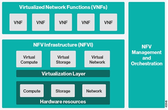
Cisco NFVI features a virtual infrastructure layer (Cisco VIM) that embeds the Red Hat OpenStack Platform (OSP).Cisco VIM includes the Newton release of OpenStack, the open source cloud operating system that controls large pools of compute, storage, and networking resources. Cisco VIM manages the OpenStack compute, network, and storage services, and all NFVI management and control functions. Key Cisco NFVI roles include:
Hardware used to create the Cisco NFVI pods include:
-
Cisco UCS® C240 M4—Performs management and storage functions and services. Includes dedicated Ceph (UCS 240-M4) distributed object store and file system. (Only Red Hat Ceph is supported).
-
Cisco UCS C220/240 M4—Performs control and compute services.
-
Cisco UCS B200 M4 blades—Can be used instead of the UCS C220 for compute and control services. The B200 blades and C240 Ceph server are connected with redundant Cisco Fabric Interconnects managed by UCS Manager.
The UCS C240 and C220 servers are M4 Small Form Factor (SFF) models with Cisco FlexFlash 64 GB Secure Digital cards and two 24 solid state storage disks (SSDs). Each UCS C240, C220, and B200 has two 10 GE Cisco UCS Virtual Interface Cards.
The B-Series pod consists of Cisco UCS B200 M4 blades for the Cisco NFVI compute and controller nodes with dedicated Ceph on a UCS C240 M4. The blades and the Ceph server are connected to redundant fabric interconnects (FIs) managed by Cisco UCS Manager. When you install Cisco VIM on a B-Series pod, you can dynamically allocate VLANs on the provider networks for both Virtio and SRIOV using the optional Cisco UCS Manager plugin. The Cisco VIM installer performs bare metal installation and deploys OpenStack services using Docker™ containers to allow for OpenStack services and pod management software updates.
The following table shows the functions, hardware, and services performed by Cisco NFVI nodes.
 Note | Internal SSD is the boot device for storage node. |
Note | Users can use any ToR that supports virtual port channel. We recommend you to use N9K SKUs as TOR, so that they can take advantage of automated ToR configuration feature which is released as part of Cisco VIM. |
Software applications that manage Cisco NFVI hosts and services include:
-
Red Hat Enterprise Linux 7.4 with OpenStack Platform 10.0—Provides the core operating system with OpenStack capability. RHEL 7.4 and OPS 10.0 are installed on all Cisco NFVI UCS servers.
-
Cisco Virtual Infrastructure Manager (VIM)—An OpenStack orchestration system that helps to deploy and manage an OpenStack cloud offering from bare metal installation to OpenStack services, taking into account hardware and software redundancy, security and monitoring. Cisco VIM includes the OpenStack Newton release with additional features and usability enhancements tested for functionality, scale, and performance.
-
Cisco Insight—Deploys, provisions, and manages Cisco VIM on Cisco UCS servers.
-
Cisco UCS Manager—Used to perform certain management functions when UCS B200 blades are installed. Supported UCS Manager firmware versions are 2.2(5a) and above.
-
Cisco Integrated Management Controller (IMC)-Provides embedded server management for Cisco UCS C-Series Rack Servers. Supported Cisco IMC firmware versions for fresh install of Cisco VIM 2.2 is: 2.0(13i) or above. Prior to upgrade of Pod from CVIM 1.0 to CVIM 2.2, it is expected that users manually upgrade to 2.0(13i) or greater. Under no circumstances can the Cisco IMC version be running 3.0 series.
-
Cisco Virtual Topology System (VTS)—is a standards-based, open, overlay management and provisioning system for data center networks. It automates DC overlay fabric provisioning for physical and virtual workloads. This is an optional service that is available through Cisco VIM.
-
Cisco Virtual Topology Forwarder (VTF)—Included with VTS, VTF leverages Vector Packet Processing (VPP) to provide high performance Layer 2 and Layer 3 VXLAN packet forwarding.
Two Cisco VNF orchestration and management applications used with Cisco NFVI include:
-
Cisco Network Services Orchestrator, enabled by Tail-f—Provides end-to-end orchestration spanning multiple network domains to address NFV management and orchestration (MANO) and software-defined networking (SDN). (For information about Cisco NSO, see Network Services Orchestrator Solutions.)
-
Cisco Elastic Services Controller—Provides a single point of control to manage all aspects of the NFV life cycle for VNFs. ESC allows you to automatically instantiate, monitor, and elastically scale VNFs end-to-end. (For information about Cisco ESC, see the Cisco Elastic Services Controller Data Sheet.)
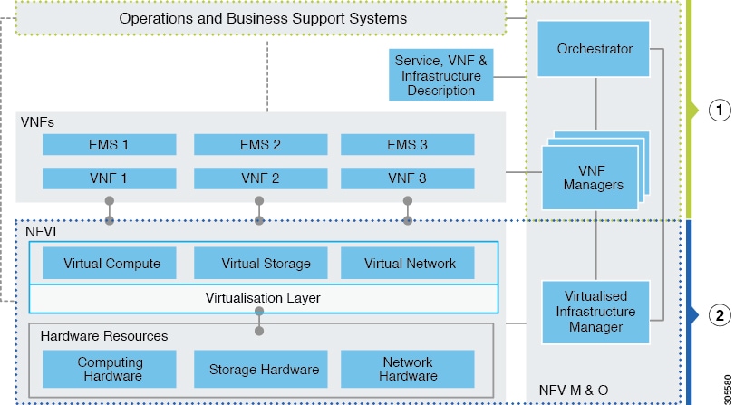
At a high level the NFVI architecture includes a VNF Manager and the NFV Infrastructure.
|
1 |
|
|
2 |
Cisco NFVI: |
For cloud networking, Cisco NFVI supports either Linux bridge over Virtual Extensible LAN (VXLAN) or Open vSwitch over VLAN as the cloud network solution for both UCS B- and C-Series pods. However, the UCS B-Series pods using the Cisco UCS Manager plugin supports only OVS/VLAN as a tenant network. Both B-Series and C-Series deployments support provider networks over VLAN. In addition, in a C-series pod, you can choose to run with augmented performance mechanism by replacing OVS/LB with VPP/VLAN (virtual packet processor). Also, in a C-series pod, you can choose to have the cloud integrated with VTC (virtual topology system), which is an SDN controller option.
The Cisco NFVI uses OpenStack services running inside containers with HAProxy load balancing and providing high availability to API and management network messaging. Transport Layer Security (TLS) protects the API network from external clients to the HAProxy. Cisco VIM installation also includes service assurance, OpenStack CloudPulse, built-in control, and data plane validation. Day two pod management allows you to add and remove compute and Ceph nodes, and replace controller nodes. The Cisco VIM installation embeds all necessary RHEL licenses as long as you use the Cisco VIM BOM and the corresponding release artifacts.
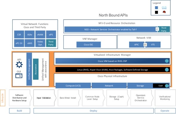
The following illustration shows a detailed view of the Cisco NFVI architecture and the Cisco NFVI Installation flow.
Overview to Cisco Virtual Infrastructure Manager
Cisco Virtual Infrastructure Manager (VIM) 2.2 is a fully automated cloud lifecycle management system. VIM helps to bring up a fully functional cloud in hours, with integrated end-to-end control and data plane verification in place. Beyond day 0 cloud bring up and deployment, VIM offers fully automated day 1 to day n cloud lifecycle management. These include capabilities such as pod scaling (expansion), software update, upgrade, or reconfigure parameters, consolidated logging with rotation and export, software update and upgrade. These have been implemented in line with the operational and security best practices of service providers and enterprises.
The following figure provides the high-level overview of all day-0 and day-n items of Cisco VIM.
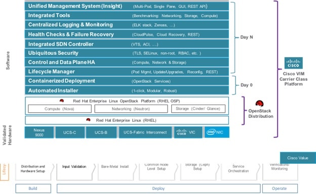
Features of Cisco VIM
Cisco VIM 2.2 is the only standalone fully automated cloud lifecycle manager offering from Cisco for private cloud. The current version of VIM, integrates with Cisco C or B-series UCS servers and Cisco or Intel NIC. This document and its accompanying admin guide help the cloud administrators to setup and manage the private cloud. Listed in table is the summary of the feature set that is offered.
Cisco NFVI Networking Overview
Cisco VIM supports installation on two different type of pods. The B-series and C-series offering supports NICs that are from Cisco (called as Cisco VIC). You can choose the C-series pod to run in a pure Intel NIC environment, and thereby obtain SRIOV support on the C-series pod. This section calls out the differences in networking between the Intel NIC and Cisco VIC installations.
To achieve network level security and isolation of tenant traffic, Cisco VIM segments the various OpenStack networks. The Cisco NFVI network includes six different segments in the physical infrastructure (underlay). These segments are presented as VLANs on the Top-of-Rack (ToR) Nexus switches (except for the provider network) and as vNIC VLANs on Cisco UCS servers. You must allocate subnets and IP addresses to each segment. Cisco NFVI network segments include: API, external, management and provisioning, storage, tenant and provider.
API Segment
The API segment needs one VLAN and two IPv4 addresses (four if you are installing Cisco VTS) (not a full subnet) in an externally accessible subnet different from the subnets assigned to other Cisco NFVI segments. These IP addresses are used for:
-
OpenStack API end points. These are configured within the control node HAProxy load balancer.
-
Management node external connectivity.
-
The Cisco Virtual Topology Services (VTS) (if included in your Cisco NFVI package) Virtual Topology Controller (VTC) node (optional for VTS).
-
VTC (optional for VTS).
External Segment
The external segment needs one VLAN to configure the OpenStack external network. Provide the VLAN during installation in the the Cisco NFVI setup_data.yaml file, but configure the actual subnet using the OpenStack API after the installation. Then use the external network to assign OpenStack floating IP addresses to VMs running on Cisco NFVI.
Management and Provisioning Segment
The management and provisioning segment needs one VLAN and one subnet with an address pool large enough to accommodate all the current and future servers planned for the pod for initial provisioning (PXE boot Linux) and, thereafter, for all OpenStack internal communication. This VLAN and subnet can be local to Cisco NFVI for C-Series deployments. For B-Series pods, the UCS Manager IP and management network must be routable. You must statically configure Management IP addresses of Nexus switches and Cisco UCS server Cisco IMC IP addresses, redundant0 , not DHCP. They must be through the API segment. The management/provisioning subnet can be either internal to Cisco NFVI (that is, in a lab it can be a non-routable subnet limited to Cisco NFVI only for C-Series pods), or it can be an externally accessible and routable subnet. All Cisco NFVI nodes (including the Cisco VTC node) need an IP address from this subnet.
Storage Segment
Cisco VIM has a dedicated storage network used for Ceph monitoring between controllers, data replication between storage nodes, and data transfer between compute and storage nodes. The storage segment needs one VLAN and /29 or larger subnet internal to Cisco NFVI to carry all Ceph replication traffic. All the participating nodes in the pod, have IP addresses on this subnet.
Tenant Segment
The tenant segment needs one VLAN and a subnet large enough to manage pod tenant capacity internal to Cisco NFVI to carry all tenant virtual network traffic. Only Cisco NFVI control and compute nodes have IP addresses on this subnet. The VLAN/subnet can be local to Cisco NFVI.
Provider Segment
Provider networks are optional for Cisco NFVI operations but are often used for real VNF traffic. You can allocate one or more VLANs for provider networks after installation is completed from OpenStack.
Cisco NFVI renames interfaces based on the network type it serves. The segment Virtual IP (VIP) name is the first letter of the segment name. Combined segments use the first character from each segment for the VIP, with the exception of provisioning whose interface VIP name is mx instead of mp to avoid ambiguity with the provider network. The following table shows Cisco NFVI network segments, usage, and network and VIP names.
For each C-series pod node, two vNICs are created using different ports and bonded for redundancy for each network. Each network is defined in setup_data.yaml using the naming conventions listed in the preceding table. The VIP Name column provides the bonded interface name (for example, mx or a) while each vNIC name has a 0 or 1 appended to the bonded interface name (for example, mx0, mx1, a0, a1).
The Cisco NFVI installer creates the required vNICs, host interfaces, bonds, and bridges with mappings created between all elements. The number and type of created vNICs, interfaces, bonds, and bridges depend on the Cisco NFVI role assigned to the UCS server. For example, the controller node has more interfaces than the compute or storage nodes. The following table shows the networks that are associated with each Cisco NFVI server role.
|
|
Management Node |
Controller Node |
Compute Node |
Storage Node |
|---|---|---|---|---|
|
Management/Provisioning |
+ |
+ |
+ |
+ |
|
ACIINFRA* |
|
+ |
+ |
|
|
API |
|
+ |
|
|
|
Tenant |
|
+ |
+ |
|
|
Storage |
|
+ |
+ |
+ |
|
Provider |
|
|
+ |
|
|
External |
|
+ |
|
Note | *ACIINFRA is only applicable when using ACI as a mechanism driver. |
In the initial Cisco NFVI deployment, two bridges are created on the controller nodes, and interfaces and bonds are attached to these bridges. The br_api bridge connects the API (a) interface to the HAProxy. The HAProxy and Keepalive container has VIPs running for each OpenStack API endpoint. The br_mgmt bridge connects the Management and Provisioning (mx) interface to the HAProxy container as well.
The following diagram shows the connectivity between Cisco NFVI nodes and networks.
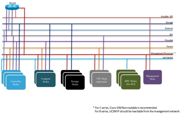
Supported Layer 2 networking protocols include:
-
Virtual extensible LAN (VXLAN) over a Linux bridge.
-
VLAN over Open vSwitch(SRIOV with Intel 710NIC).
-
VLAN over VPP/VLAN for C-series Only.
-
For UCS B-Series pods, Single Root Input/Output Virtualization (SRIOV). SRIOV allows a single physical PCI Express to be shared on a different virtual environment. The SRIOV offers different virtual functions to different virtual components, for example, network adapters, on a physical server.
Any connection protocol can be used unless you install UCS B200 blades with the UCS Manager plugin, in which case, only OVS over VLAN can be used. The following table shows the available Cisco NFVI data path deployment combinations.
|
NFVI Pod Type |
Pod Type |
Mechanism Driver |
Tenant Virtual Network Encapsulation
|
Provider Virtual Network Encapsulation |
SRIOV for VM |
PCI Passthrough Ports |
MTU Values
|
||
|---|---|---|---|---|---|---|---|---|---|
|
|
|
|
VLAN |
VxLAN |
VLAN |
|
|
1500 |
9000 |
|
UCS C-series |
Full on |
LinuxBridge |
No |
Yes |
Yes |
No |
No |
Yes |
No |
|
UCS C-series |
Full on, micro, HC |
Openvswitch |
Yes |
No |
Yes |
Yes* |
No |
Yes |
Yes |
|
UCS C-series |
Full on, micro |
VPP |
Yes |
No |
Yes |
No |
No |
Yes |
Yes |
|
UCS C-series |
Full on, micro |
ACI |
Yes |
No |
Yes |
No |
No |
Yes |
Yes |
|
UCS C-series |
Full on |
VTF with VTC*** |
No |
Yes |
Yes |
No |
No (except through DPDK) |
Yes |
Yes |
| UCS B |
Full on |
Openvswitch | Yes | No | Yes | Yes | No | Yes | Yes |
Note | Fullon: Indicates dedicated control, compute and ceph nodes. |
Micro: Indicates converged control, compute and ceph nodes
HC (Hyperconverged): Indicates dedicated control, compute, but all ceph nodes are compute nodes also
Note | *** VTF with VTC is only supported on C-series Cisco VIC. |
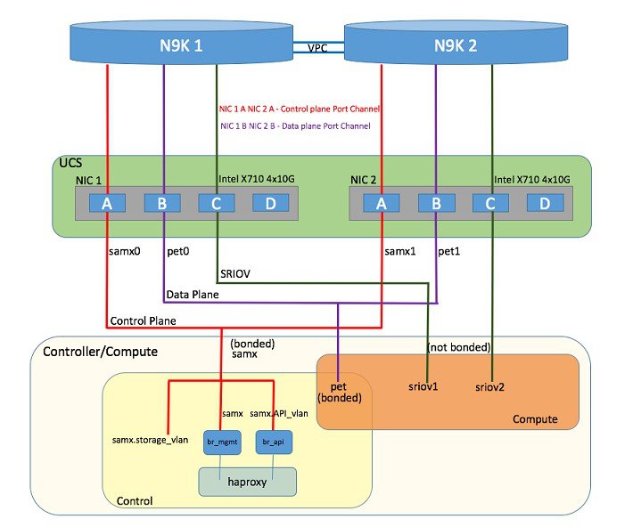
Pod with Intel NICs In case of the pod having Intel NICs (X710), the networking is slightly different. First of all, the requirement is to have atleast two NICs (4x10G) single server, so that we can support NIC level redundancy. Each NIC is connected to each ToR (connections explained later in the chapter). Since vNICs are not supported in the Intel card, the idea is to bond the physical interfaces at the host and then create sub-interfaces based on the segment VLAN. Lets call the two NIC cards as NIC_1 and NIC_2 and call their four ports as A, B, C, D. Unlike Cisco VIC based pod, the traffic here is classified into the following.
-
Control Plane.
- Data plane (external, tenant and non-SRIOV provider network).
- SRIOV (optional for provider network); if SRIOV is used the Data plane network only carries external and tenant network traffic.
Control Plane.
The control plane is responsible for carrying all the control and management traffic of the cloud. The traffic that flows through control plane are:
The control plane interface is created by bonding the NIC_1 A port with NIC_2 A port. The bonded interface name is called as samx, indicating that it is carrying Storage, API, Management/Provision traffic (naming convention is similar to Cisco VIC pod). The slave interfaces (physical interfaces) of the bonded interface are renamed as samx0 and samx1. samx0 belongs to NIC_1 and samx1 belongs to NIC_2. Sub interfaces are then carved out of this samx interface based on the Storage, API VLANs. The management/provision traffic will be untagged/native VLAN in order to support pxe booting.
Data Plane
The data plane is responsible for carrying all the VM data traffic. The traffic that flows through the data plane are
The data plane is created by bonding the NIC_1 B port with NIC_2 B port. The bonded interface name here would be pet, indicating that it is carrying Provider, External and Tenant traffic. The slave interfaces of this bonded interface would be visible as pet0 and pet1. pet0 belongs to the NIC_1 and pet1 belongs to NIC_2.
In case of OVS/VLAN, the "pet" interface is used as it is (trunked to carry all the data VLANs) to the Openstack cloud, as all the tagging and untagging happens at the Openstack level. In case of Linux Bridge/VXLAN, there will be sub-interface for tenant VLAN to act as the VXLAN tunnel endpoint.
SRIOV
In case of Intel NIC pod, the third (and optionally the fourth) port from each NIC can be used for SRIOV traffic. This is optional and is set/unset through a setup_data.yaml parameter. Unlike the control and data plane interfaces, these interfaces are not bonded and hence there is no redundancy. Each SRIOV port can have maximum of 32 Virtual Functions and the number of virtual function to be created are configurable through the setup_data.yaml. The interface names of the sriov will show up as sriov0 and sriov1 on each host, indicating that sriov0 belongs to NIC_1 C port and sriov1 belongs to NIC_2 C port.
In the case of Intel NIC testbeds, the following table summarizes the above discussion
|
Network |
Usage |
Type of traffic |
Interface name |
|---|---|---|---|
|
Control Plane |
To carry control/management traffic |
Storage, API, Management/Provision |
samx |
|
Data Plane |
To carry data traffic |
Provider, External, Tenant |
pet |
|
SRIOV |
To carry SRIOV traffic |
SRIOV |
sriov0, sriov1 |
The following table shows the interfaces that are present on each type of server (role based).
|
|
Management Node |
Controller Node |
Compute Node |
Storage Node |
|---|---|---|---|---|
|
Installer API |
+ |
|
|
|
|
Control plane |
+ |
+ |
+ |
+ |
|
Data plane |
|
+ |
+ |
|
|
SRIOV |
|
|
+ |
|
Note | On an Intel testbed, all kind of OpenStack networks should be created using physnet1 as the physnet name. |
UCS C-Series Network Topologies
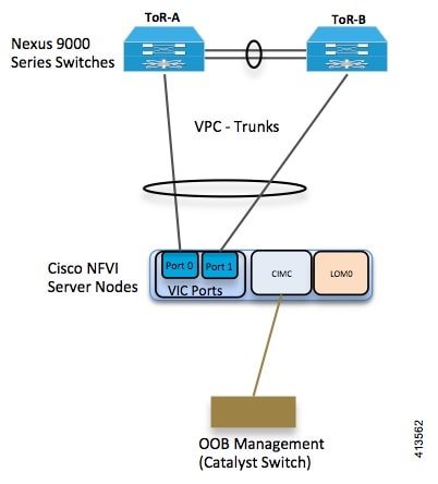
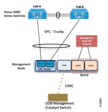
Cisco NFVI UCS servers connect to the ToR switches using Cisco UCS dual-port Virtual Interface Cards (VICs). The VIC is an Enhanced Small Form-Factor Pluggable (SFP+) 10 Gigabit Ethernet and Fibre Channel over Ethernet (FCoE)-capable PCI Express (PCIe) card designed for Cisco UCS C-Series Rack Servers. Each port connects to a different ToR using a Virtual Port Channel (VPC). Each VIC is configured with multiple vNICs that correspond to specific Cisco VIM networks. The UCS Cisco IMC port is connected to an out-of-band (OOB) Cisco management switch. The following figure shows the UCS C-Series pod Cisco NFVI host to ToR topology.
In the case of Intel NIC, a single two port Cisco VIC in the preceding diagram, is replaced with two 4-port 710 Intel NIC. The addition of an extra Intel NIC has been done to incorporate the user request of providing card level redundancy which the Cisco VIC solution does not have.
Of the four ports that are available in each NIC card, port A is used for management traffic (provision, API, storage, etc), whereas the port B is used for data plane (tenant and provider network) traffic. Port C (and optionally Port D) is dedicated for SRIOV (configured optionally based on setup_data.yaml). Sub-interfaces are carved out of the data and control plane interfaces to provide separate traffic based on specific roles. While port A and B from each NIC help in forming bonded interface, ports C and D over which SRIOV traffic for provider network flows is not bonded. Extreme care should be taken during pod setup, so that ports A, B and C for the Intel NIC is connected to the ToRs. In VIM 2.2,Port D can be optionally used as a 2nd pair of SRIOV ports.
In VIM 2.2, computes running a Cisco 1227 VIC, and 2 2-port Intel 520 NIC is also supported. In this combination, SRIOV is running on the Intel NIC, where as rest of the control and data plane are carried by vritual interfaces over Cisco VIC.
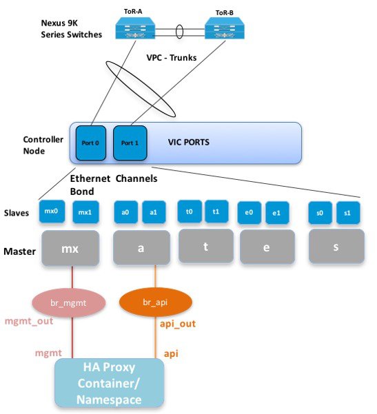
The Cisco NFVI controller node has four bonds: mx, a, t, and e. Each has a slave interface that is named with the network name association and a mapped number. For example, the management and provisioning network, mx, maps to mx0 and mx1, the API network, a, to a0 and a1, and so on. The bonds map directly to the vNICs that are automatically created on the controller node when it is deployed. The following figure shows the controller node network-to-bond-to-vNIC interface mapping.
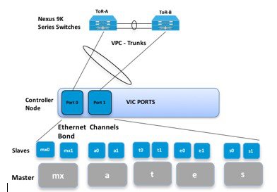
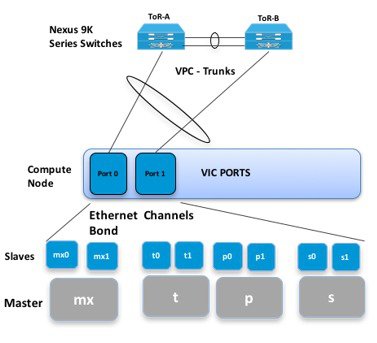
The Cisco NFVI compute node has three bonds: mx, t, and p. Each has a slave interface that is named with the network name association and a mapped number. For example, the provider network, p, maps to p0 and p1. The bonds map directly to the vNICs that are automatically created on the compute node when it is deployed. The following figure shows the compute node network-to-bond-to-vNIC interfaces mapping.
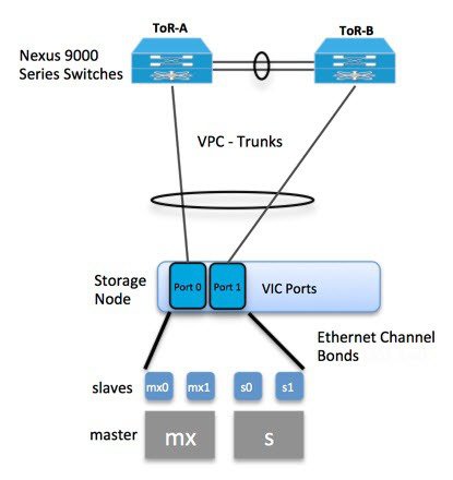
The Cisco NFVI storage node has two bonds: mx and s. Each has a slave interface that is named with the network name association and a mapped number. For example, the storage network, s, maps to s0 and s1. Storage nodes communicate with other storage nodes over the mx network. The storage network is only used for Ceph backend traffic. The bonds map directly to the vNICs that are automatically created on the storage node when it is deployed. The following figure shows the network-to-bond-to-vNIC interfaces mapping for a Cisco NFVI storage node.
The initial Cisco NFVI installation creates two bridges on the controller nodes and interfaces and bonds are attached to the bridges. The br_api bridge connects the API (a) interface to the HAProxy container. The HAProxy and Keepalive container has VIPs running for each OpenStack API endpoint. The br_mgmt bridge connects the Management and Provisioning (mx) interface to the HAProxy container as well.
The figure below shows the connectivity between the mx interface and the br_mgmt bridge. It also shows the connectivity between the br_mgmt and the HAProxy container/namespace using mgmt_out and mgmt interfaces. The figure shows the connectivity between the api interface and the br_api bridge as well as the link between the br_mgmt bridge and the HAProxy container using api_out and mgmt_out interfaces.
A sample routing table is shown below. br_api is the default route and br_mgmt is local to the pod.
[root@c43-bot-mgmt ~]# ip route
default via 172.26.233.193 dev br_api  proto static  metric 425
172.26.233.0/25 dev br_mgmt  proto kernel  scope link  src 172.26.233.104  metric 425
172.26.233.192/26 dev br_api  proto kernel  scope link  src 172.26.233.230  metric 425

[root@c43-bot-mgmt ~]# ip addr show br_api
6: br_api: <BROADCAST,MULTICAST,UP,LOWER_UP> mtu 1500 qdisc noqueue state UP
    link/ether 58:ac:78:5c:91:e0 brd ff:ff:ff:ff:ff:ff
    inet 172.26.233.230/26 brd 172.26.233.255 scope global br_api
       valid_lft forever preferred_lft forever
    inet6 fe80::2c1a:f6ff:feb4:656a/64 scope link
       valid_lft forever preferred_lft forever

[root@c43-bot-mgmt ~]# ip addr show br_mgmt
7: br_mgmt: <BROADCAST,MULTICAST,UP,LOWER_UP> mtu 1500 qdisc noqueue state UP
    link/ether 58:ac:78:5c:e4:95 brd ff:ff:ff:ff:ff:ff
    inet 172.26.233.104/25 brd 172.26.233.127 scope global br_mgmt
       valid_lft forever preferred_lft forever
    inet6 fe80::403:14ff:fef4:10c5/64 scope link
       valid_lft forever preferred_lft forever
Cisco VIM Management Node Networking
In Cisco VIM, the management node has two interfaces. One for API and the other for provisioning. This was primarily done for security reasons so that internal pod management or control plane messages (RabbitMQ, Maria DB and so on) do not leak out, and hence reduce the attack vector to the pod. As the name indicates, the API interface is to access the VIM installer API and also is used to SSH to the management node. All external services (installer API, Insight, ELK and so on) are password protected and hangs off the API interface. Default route of the management node points to the API interface.
The second interface, also called the provisioning interface is used to PXE boot the various nodes that constitute the OpenStack pod. Typically, this is a non-routable interface reserved for OpenStack management traffic.
In the case of B-series pod, the networks between provisioning and the UCSM IP need to be routable. Proper ACL should be applied in the upstream router so that other networks does not interfere with the provisioning network. Depending on the overall deployment, the management node will also act as a jump-server to the OpenStack nodes. Listed figure is the high level layout of the Cisco VIM pod, along with the management-node networking design.
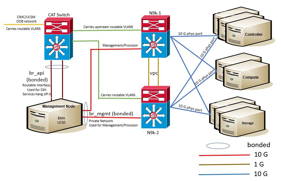
Cisco NFVI UCS C-Series management node physically connects to the network. Unlike other nodes, the management node does not use multiple vNICs corresponding to specific Cisco NFVI networks. Instead, it connects to the management and API networks using two different physical connections. The management node connects to the management network using a Cisco two-port VIC with each port connecting to a different ToR switch in a VPC configuration. The Cisco VIC card utilizes the default vNICs, but requires the vNICs to be in trunk mode and the default VLAN set to the management network VLAN. The management node connects to the API network using both one Gbps LAN On Motherboard (LOM) ports connected in a port channel configuration. These ports can either connect to the Nexus 9000 Series switch in a VPC configuration, or to an operator-managed switch(es), depending on how the operator wants to segment their network. The Cisco IMC port can optionally be connected to an out-of-band management Catalyst switch.
Management node services, which are required to start the other topology nodes, listen on the management network and the traffic flowing over the vNICs. These services, as well as many of the other management network services, are unsecured. Secure management node services listen on the management node API network, and their traffic flows over the LOM ports. This service division allows tenants to utilize tighter network access control to the management network than the management node API network. The following figure shows the Cisco NFVI management node (UCS C-Series) API network connections.
Note | Connecting Cisco IMC port to a Cisco OOB management switch is optional. |
IPv6 Support on Management Network
Users are transiting from IPv4 to IPv6 due to the limited number of available routable IPv4 networks. Today in Cisco VIM, the management network is in IPv4. In Cisco VIM, the management network uses the default IPv4 route to reach external service like NTP, DNS, AD/LDAP, SwiftStack, etc if its not locally hosted.
With limited availability of IPv4 address-space, it can become a deployment hindrance for users who cannot provide a routable IPv4 network or local/dual-home of their external services (AD/LDAP is an example where its hosted in the corporate network and require routing to get to it).
IPv 4 is obligatory in Cisco VIM, as the provision network co-locates with management network (mx/samx interface); for baremetal PXE install and Ansible orchestration.
As CEPH and OpenStack control plane communication are on the same management network, it is difficult to completely remove IPv4 from the management network. So we recommend you to run IPv4+IPv6 dual stack, in which IPv4 network can exist in a non-routable private network and IPv6 network can be in a routable semi-private network. This satisfies both requirements of the CiscoVIM and the user's accessibility to their external services.
In CiscoVIM 2.2, IPv6 addresses of the management network for servers and management node is statically allocated from a given pool. The external services, which support both IPv4 and/or IPv6 addresses, are DNS, NTP, AD/LDAP. Users, can run IPv4+IPv6 (optionally) as their cloud api end-point.
UCS C-Series and B-Series Topologies
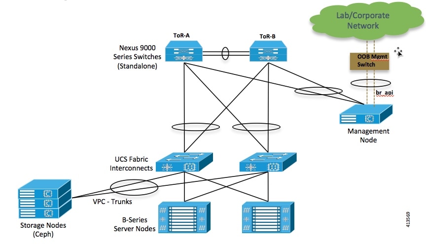
You can deploy Cisco NFVI using a combination of Cisco C-Series and B-Series servers. The figure below shows a high-level view of Cisco UCS C-Series and B-Series servers used in a Cisco NFVI deployment. The C-Series management node is connected to the Nexus 9000 Series ToRs through the Cisco VIC in a VPC configuration. The UCS Fabric Interconnects (FIs) are connected to the ToRs and the UCS B-Series blade chassis is connected to the FIs. The C-Series storage nodes are connected to the ToRs as well. The networking segment layout discussed in Cisco NFVI Networking Overview is the same for a C-Series-only implementation or the C-Series and B-Series design shown below with two exceptions:
-
For the UCS B-Series, the Cisco UCS Manager IP address must be available to the Cisco NFVI management network. For UCS C-Series, this requirement is optional.
-
The UCS Manager cluster and VIP connections are usually not attached to one of the Cisco NFVI network segments.
For C-Series pods, each host has a 2x10 GE Cisco network card 1227 from which the installer creates two vNICs for each network to ensure the network topology has built-in redundancy. The provider network, if needed, is also created from the same network card. Each link of a given network type terminates to a unique Nexus 9000 switch, which acts as the ToR. The Nexus 9000s are configured in VPC mode to ensure network redundancy is built into the design from the beginning. The networking redundancy is extended to the management node, which has a redundant vNIC for the installer API and management or provisioning networks. The figure shows the C-Series topology.
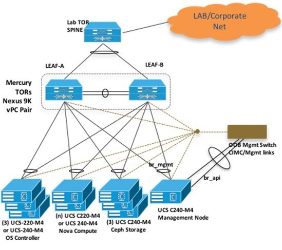
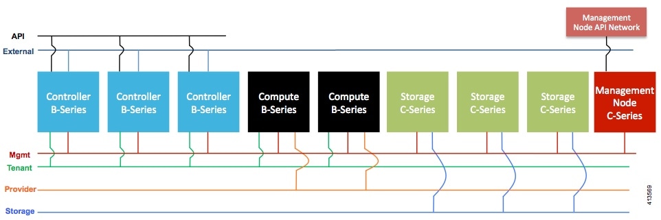
Note | While the figure depicts UCS 220 M4s as controller and compute, it also supports UCS 240 M4s as control and compute nodes. Cisco NFVI uses multiple networks and VLANs to isolate network segments. For the UCS C-Series management and storage nodes, VLANs are trunked between the ToR switches and the Cisco VICs on the C-Series nodes. For the UCS B-Series controllers and compute nodes, VLANs are trunked between the ToR switches, the UCS Fabric Interconnects, and the B-Series blades. The figure shows the network segments and how each node is attaches to them. The network segments are VLANs that are trunked between the respective upstream switch/FI and the C-Series or B-Series node. |
Cisco NFVI High Availability
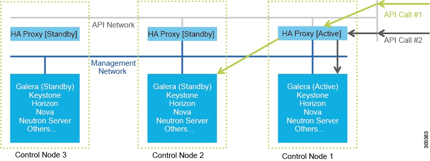
Cisco NFVI high availability (HA) is provided by HAProxy, a single-threaded, event-driven, non-blocking engine combining a very fast I/O layer with a priority-based scheduler. HAProxy architecture is layered with bypass mechanisms at each level to ensure data does not reach higher levels than needed. Most processing is performed in the kernel.
The following figure shows a detailed view of Cisco NFVI controllers connecting to the API and Management and Provisioning network. It also shows how the bridges are configured and the roles of the HAProxy container and network namespace. The dedicated HAProxy container network namespace was created to avoid split default gateway problems. The namespace allows API segment ingress and egress traffic to have a different default gateway than the one configured on each controller host for non-API traffic. In the illustration, two of the three Cisco NFVI controllers have HAProxy containers as well as a dedicated Linux network namespace. (Cisco NFVI supports three HAProxy containers.)
In the figure, Control Node 1 is attached to the API network segment through the br_api bridge. The br_api bridge connects to the Linux network namespace where the HAProxy container has an interface mapped through the api < > api_out interface mapping shown in the previous figure. The HAProxy container has a default gateway configured that points to the upstream API Layer 3 First Hop Redundancy Protocol (FHRP) VIP. This gateway is used for HAProxy container incoming and outgoing API traffic.
Outside traffic coming in through the API interface is routed into the API network. The traffic traverses the br_api bridge, goes into the Linux network namespace and then the API VIP (based on IP address/port) that is listening on the HAProxy container. The HAProxy container establishes a connection with the backend API endpoint (for example, the OpenStack Horizon dashboard) and the return traffic will pass back through the container and back out the API network following the default gateway for the container on the API network. All other non-API traffic such as the management access over SSH to the Cisco VIM controller will come into the management/provisioning network and access the node directly. Return traffic will use the host-level default gateway configured on the Linux (RHEL) operating system.
If an HA event occurs in a Cisco NFVI pod, Cisco VIM automatically shuts down machines by failing over services. Examples include:
-
For API servers, HAProxy automatically ensures that other redundant control services handle requests, avoiding the shutdown/terminated/non-responding one.
-
For quorum services, such as Galera, the remaining members of the quorum continue to provide service and HAProxy ensures that new requests go to the remaining processes.
-
For an active/standby process such as HAProxy, the system moves the endpoint IP to a standby copy and continues to operate.
All of these behaviors are automatic and do not require manual intervention. When the server is restarted, the services automatically come into service and are added to the load balancing pool, joining their quorums or are added as backup services, depending on the service type.
While manual intervention is generally not needed, some specific failure scenarios (for example, Mariadb, rabbit ) can cause problems that require manual intervention. For example, if a complete network failure occurs, the Galera and RabbitMQ clusters can go into three-way partition. While Cisco NFVI cluster is resilient to single-point failures, two switches failing simultaneously—something highly unlikely in long-running systems—can sometimes happen due to administrative error, in which case, manual intervention is needed. To repair the pod, the management node must be up and running and all the nodes accessible through password-less SSH from the management node. From the installer<tagid> dir, execute:
# ciscovim cluster-recovery
Control nodes will recover after the network partitions are resolved. After executing this command, control nodes services should come back to working state. To make sure Nova services are good across the compute nodes, execute the following command after sourcing /root/openstack-configs/openrc:
# nova service-list
To check for the overall cloud status, execute the following:
# cd installer-<tagid>/tools
# ./cloud_sanity.py -c all
Cisco NFVI Storage Node Overview
Block Storage
Cisco NFVI storage nodes utilize Ceph, an open source software for creating redundant, scalable data storage using clusters of standardized servers to store petabytes of accessible data. OpenStack Object Storage is a long-term storage system for large amounts of static data that can be retrieved, leveraged, and updated. It uses a distributed architecture with no central point of control, providing greater scalability, redundancy, and permanence. Objects are written to multiple hardware devices, with the OpenStack software responsible for ensuring data replication and integrity across the cluster. Storage clusters scale horizontally by adding new nodes. if a node fail, OpenStack replicates its content across other active storage nodes. Because Ceph uses software logic to ensure data replication and distribution across different devices, inexpensive commodity hard drives and servers can be used in lieu of more expensive equipment.
Cisco NFVI storage nodes include object storage devices (OSDs), hard disk drives (HDDs), and solid state drives (SSDs). OSDs organize data into containers called objects that a user or application determines are related. The objects reside in a flat address space where they all exist at the same level and cannot be placed inside one another. Each OSD has a unique object identifier (OID) that allows the Cisco NFVI control node to retrieve it without knowing the physical location of the data it contains.
HDDs store and retrieve digital information using one or more rigid rapidly rotating disks coated with magnetic material. The disks are paired with magnetic heads arranged on a moving actuator arm, which read and write data to the disk surfaces. Data is accessed in a random-access manner; individual data blocks can be stored or retrieved in any order and not only sequentially. HDDs are a type of non-volatile memory, retaining stored data even when powered off.
SSDs are solid-state storage devices that use integrated circuit assemblies as memory to store data persistently. SSDs primarily use electronic interfaces compatible with traditional block input/output (I/O) hard disk drives, which permit simple replacements in common applications.
Cisco NFVI storage nodes are managed by the control node applications including Ceph monitoring dashboard, Glance, and Cinder. The Ceph monitoring dashboard provides a view into the overall storage node health. Glance virtualizes pools of block storage devices and provides a self-storage API to request and consume those resources. Cinder is an OpenStack block storage service designed to present storage resources to the OpenStack compute node.
In 2.2 release of Cisco VIM, depending on the customer needs, the number of OSDs a pod can have is between 3 and 20.
Object Storage
Cisco VIM provides an integration with SwiftStack, an object storage solution. In this case, the SwiftStack is installed and managed outside the Cisco VIM ahead of time, and the VIM orchestrator adds the relevant Keystone configuration to access the SwiftStack endpoint. In addition to Keystone integration, the Cinder service is also configured to support backup of the volumes to SwiftStack object store. In the current integration, the SwiftStack endpoint has to be in a network routable to/from the CiscoVIM API network (as the VIM API is the same as the Keystone public endpoint network). In the current release, because of limitations in SwiftStack, Cisco VIM is integrated only with KeystoneV2.
Overview to Cisco Virtual Topology System
The Cisco Virtual Topology System (VTS) is a standards-based, open, overlay management and provisioning system for data center networks. It automates data center overlay fabric provisioning for both physical and virtual workloads.
Cisco VTS provides a network virtualization architecture and software-defined networking (SDN) framework that meets multitenant data center cloud service requirements. It enables a policy-based approach for overlay provisioning.
Cisco VTS automates network overlay provisioning and management tasks, integrates with OpenStack and simplifies the management of heterogeneous network environments. Cisco VTS provides an embedded Cisco VTS GUI and a set of northbound Representational State Transfer (REST) APIs that can be consumed by orchestration and cloud management systems.
Cisco VTS architecture has two main components: the Policy Plane and the Control Plane. These perform core functions such as SDN control, resource allocation, and core management function.
-
Policy Plane—Enables Cisco VTS to implement a declarative policy model that captures user intent and converts it into specific device-level constructs. Cisco VTS includes a set of modular policy constructs that can be organized into user-defined services for use cases across service provider and cloud environments. The policy constructs are exposed through REST APIs that can be consumed by orchestrators and applications to express user intent, or instantiated through the Cisco VTS GUI. Policy models are exposed as system policies or service policies.
-
Control Plane—Serves as the SDN control subsystem that programs the various data planes including the VTFs residing on the x86 servers, hardware leafs, DCI gateways. The control plane hosts the Cisco IOS XRv Software instance that provides route peering capabilities between the DCI gateways or to a BGP route reflector. (Cisco IOS XRv is the virtualized version of Cisco IOS XR Software.) The control plane enables an MP-BGP EVPN-based control plane for VXLAN overlays originating from leafs or software VXLAN tunnel endpoints (VTEPs)
The Cisco NFVI implementation of Cisco VTS includes the VTS Virtual Topology Forwarder (VTF). VTF provides a Layer 2/Layer 3 (L2/L3) software switch that can act as a software VXLAN terminal endpoint (VTEP). VTF is a lightweight, multitenant software data plane designed for high performance packet processing on x86 servers. VTF uses Vector Packet Processing (VPP). VPP is a full-featured networking stack with a software forwarding engine. VTF leverages VPP and the Intel Data Path Development Kit (DPDK) for high performance L2, L3, and VXLAN packet forwarding.
VTF allows Cisco VTS to terminate VXLAN tunnels on host servers by using the VTF as a software VXLAN Tunnel Endpoint (VTEP). Cisco VTS also supports hybrid overlays by stitching together physical and virtual endpoints into a single VXLAN segment.
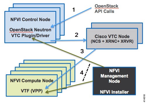
The figure below shows the Cisco VTS architecture and high-level flow when installed in Cisco NFVI. Cisco VTS is installed on separate UCS servers, the Virtual Topology Controller plugin is installed on the control node, and the VTF is installed on the compute node.
-
The OpenStack user invokes the OpenStack Neutron API.
-
Neutron uses the VTS plugin and driver to make calls to the VTC REST API.
-
VTS control components interact with the VTF agent to carry out the corresponding dataplane setup.
-
During Cisco NFVI installation, the Cisco NFVI Installer installs the OpenStack Neutron VTC plugin and driver on the Cisco NFVI controller node, and installs the VTF component (including VPP) on the Cisco NFVI compute node.
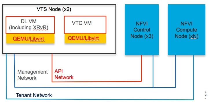
The following illustration shows the Cisco NFVI networking after Cisco VTS is installed. The SDN controller nodes are an addition to the existing Cisco NFVI pod.
Overview to Cisco NFVIMON
Cisco VIM solution uses Cisco NFVI Monitor (NFVIMON) to monitor the health and performance of the NFVI. This includes monitoring both the physical and logical components of one or multiple NFVI pods. The NFVIMON feature is enabled by Zenoss which provides for extensive monitoring and collection of performance data for various components of the cloud infrastructure including Cisco UCS blade and rack servers, service profiles, Nexus top of rack switches, fabric interconnects, and also the OpenStack instances. The monitoring system is designed such that it can monitor single or multiple pods from a single management system. NFVIMON is integrated into Cisco VIM as an optional component. NFVIMON is enabled by extending the setup_data.yaml file with relevant information. To enable NFVIMON refer to Enabling NFVIMON on Cisco VIM. Also, NFVIMON can be enabled on an existing pod, through the reconfigure option. To reconfigure through Insight UI, refer Reconfigure Optional Services. Then, the pod is added as a new VIM resource to be monitored in the Monitoring UI.
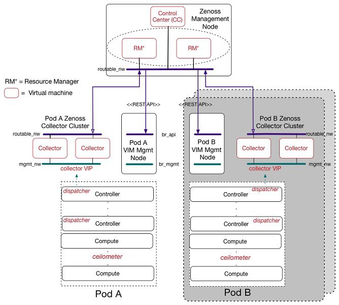
The NFVIMON architecture supports monitoring of one or more Cisco VIM pods. There is no limit on the number of pods, but note that the setup supports up to 2600 managed resources across pods, where a managed resource is a physical device, network device or virtual machine tracked from a monitoring perspective.
NFVIMON consists of four components: dispatcher, collector, resource manager (RM) and control-center (CC) with Cisco Zenpacks. As NVIFMON is a third party software, make sure its integration into VIM is loosely coupled and the VIM automation only deals with installing the minimal software piece (dispatcher) needed to monitor the pod. The installing of the other NFVIMON components (collector, resource manager (RM) and control-center (CC) with Cisco NFVI Zenpacks) are Cisco Advance Services led activity and those steps are outside the scope of the current install guide. Make sure that you have engaged with Cisco Advance Services on the planning, image information (of collector(CC) with Cisco NFVI Zenpacks and RM), and installation of the NFVIMON accessories along with its network requirements. You can start with one Cisco VIM pod (pod A in the picture) and two external nodes (one to host 2 Collector VMs and one for remote management to host 1 control-center with Cisco Zenpacks and 2 RM VMs) of multiple pods.
Cisco VIM pods can be monitored at the time of installing with NFVIMON enabled, or by adding NFVIMON as a post install feature. Install the collectors manually in the external collector node, and now the pod is added for monitoring in the control center. Also, it should be noted that NFVIMON is only supported on a pod running Keystone v2.
Overview to Cisco VIM Insight
CiscoVIM Insight, a light-weight UI, is introduced in Cisco VIM to ease the deployment and management of the NFVI platform. Also, Cisco VIM Insight offers a single pane of glass service to provide deployment visualization and to manage multiple Cisco VIM pods thereby reducing user-errors.
Cisco VIM Insight supports multi-tenancy with local RBAC support and is easily integrated with the CiscoVIM REST layer. The container based UI platform is loosely coupled, and can help manage multiple CiscoVIM pods right from day-0, or later in the lifecycle of the cloud.
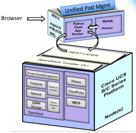
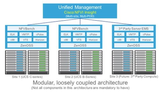
The architecture of the CiscoVIM Insight is light-weight, hierarchical and scalable. While it introduces an ease of management from the global UI, each local site is autonomous with localized toolsets. The Global Unified Management UI, provides ease of management with multi-site multi-pod capability for distributed NFV deployment at scale. Also, CiscoVIM Insight is designed to operate in HA as an option. The platform is a modular, loosely coupled architecture, that will provide the capability to manage multiple pods, with RBAC support as shown in the figure .
Overview to NFVBench
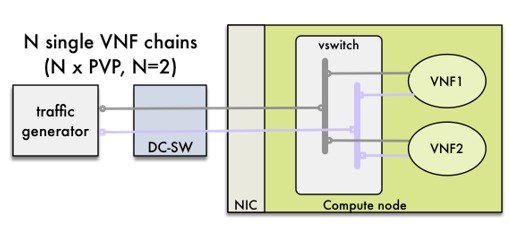
NFVBench is a containerized network benchmarking tool introduced in Cisco VIM, to bring consistent methodology to measure network performance of the cloud. NFVBench is offered in a container that is pre-installed on the management node.
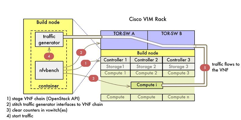
The main goal of NFVBench is to measure cloud performance based on real cloud deployments and not on synthetic, hypothetical lab test environment. Therefore, during the test, the packet path must traverse through every network element that participates in the production environment; that is traffic flows through switch (ToR) to v-switch on compute node, continues to VM representing any basic VNF in NFV deployment and comes back similar way on different ports. Network performance or throughput is computed based on sent and received traffic.
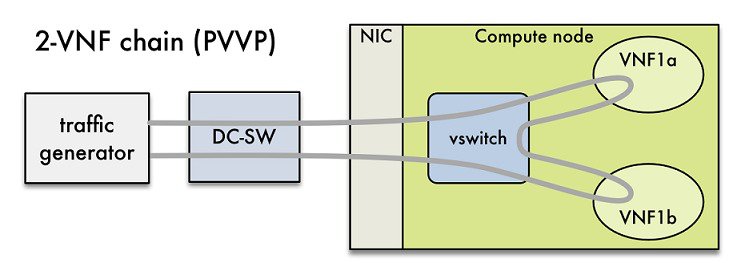
Also it helps to verify network configuration and possible bottlenecks. Reports from NFVBench show data measurements from every element in path, which makes it easier to detect configuration errors or potential bottlenecks. NFVBench sends Layer2 or Layer3 packets generated by open-source traffic generator (TRex) already included in container. Advanced testing using NFVBench allows to conduct multi-chaining and multi-flow testing. The multi-chaining testing enables to run multiple parallel independent packet paths at the same time, while the multi-flow testing performs IP ranging in packet headers within every chain.
NDR/PDR and Fixed Rate Tests
NDR/PDR Test: NFVBench offers a more advanced test (called the NDR/PDR test), provides information about network throughput using any of the standard defined packet sizes - 64B, IMIX, 1518B. NDR (No Drop Rate) value represents throughput at which no packets are dropped (this is in reality satisfied by less than 0.001 % of packets being dropped). Similarly, PDR (Partial Drop Rate) represents throughput at which only small number of packets is dropped (usually less than 0.1 % of packets sent).
Fixed Rate Test: NFVBench offers a simple test to run traffic at fixed rate, which verifies that every network component of packet path works properly. It is also very useful for identifying bottlenecks in the test environment. Traffic generator generates packets at fixed rate for period of time specified by user. From the statistics collected, drop rates and latencies are computed and displayed.
Both the NDR/PDR Test and Fixed Rate Test types of test provide good way of verifying network performance of NFV solution.
Overview to ACI Plugin Integration
The following section gives you an overview of a typical architecture for an ACI fabric with an OpenStack deployment. An ACI with OpenStack deployment consists of a Nexus 9000 Spine/Leaf topology, an APIC cluster, a minimum of 3-node cluster of Controllers (which are also acting as the Neutron network node),and two or more compute nodes to host Virtual Machine (VM) instances.
An ACI External Routed Network connection as a Layer 3 connection outside of the fabric can be used to provide connectivity outside the OpenStack cloud, as depicted in the following figure.
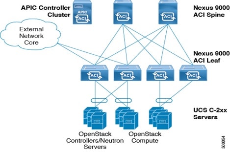
Note | Basic ACI architecture can be obtained at documentation available in CCO. |
In Cisco VIM 2.2, we have integrated the Opflex ML2 plugin (in Unified mode) to manage the tenant VLANs dynamically, as VMs come and go in the cloud. By utilizing OpFlex, the policy model native to ACI can be extended all the way down into the virtual switches running on OpenStack Nova compute hosts. OpFlex extension to the compute host allows ACI to use Open vSwitch (OVS) to support common OpenStack features such as Source NAT (SNAT) and Floating IP in a distributed manner.
Cisco VIM 2.2 also extends the automation to include the day-0 ToR level configuration needed to work with ACI, except for L3 out. The exception for L3 out was made because users can configure their upstream infrastructure in different ways.
Note | Cisco VIM 2.2 has been validated against APIC 3.0, hence it is imperative to use APIC 3.0 version only. |
Disk Management in VIM 2.2
Cisco VIM 2.2 uses the disk-maintenance tool that gives the user the ability to check the status of all hard disk drives present in the running and operational mode in the following nodes:
Status of the disks such as online, offline, rebuilding helps you to identify which particular disks in which slot have potentially gone bad and require to be physically replaced in the server. It can be run on servers that have either a RAID controller or an SAS passthrough controller.
Once the disk(s) is physically replaced, Disk management tool can be used to add the new disk back into the system as part of the RAID system (recommended one server at a time).
Note | Disk Maintenance tool is useful only when one or at most two (in RAID6) go bad and need to be replaced. Failure of more than one disks at a time puts the entire server in an irrecoverable state and at that point the server has to be necessarily replaced using remove and add operations through ciscovim. |
OSD Maintenance
OSD maintenance tool gives the user the ability to check the status of all OSDs and their corresponding physical hard disk drives present in the running and operational storage nodes. The status of the OSDs is reported along with the HDD mapping.
OSD Maintenance tool helps you to identify the status of the OSD (Up/Down) and its corresponding hard disk drive slot in the server that requires to be physically replaced. OSD Maintenance tool can run on servers that have either a RAID or an SAS passthrough controller.
Once the HDD to be physically replaced is identified, the same OSD tool can be used to first rebalance the ceph tree, remove the OSD from the cluster and unmount the disk drive, in preparation for the disk removal. After the disk has been physically replaced, the tool can also be used to add the new disk back into the system as part of the Ceph cluster and recreate the OSD (only one HDD/OSD at a time). It ensures that just to replace a bad HDD, it is not necessary to remove the ceph cluster from operation and then add it back through remove-storage and add-storage options in ciscovim.
Note | OSD tool in this release does not support the replacement of the internal OS drives and the external journal drives, for which the user still needs to use add/remove of OSD nodes. |
 Feedback