- Overview to Cisco NFVI
- Cisco NFVI Installation Overview
- Preparing for Installation on Servers Without Internet Access
- Preparing for Cisco NFVI Installation
- Installing Cisco VTS
- Installing Cisco VIM
- Installing Cisco VIM Insight
- Installing Cisco VIM through Cisco VIM Insight
- Verifying the Cisco NFVI Installation
- Registering New Pod to Insight
- Configuring OpenStack Installation
- Post Installation Features for Active Blueprint
- Monitoring the Pod
- Cross Launching Horizon
- NFVI Monitoring
- Run VMTP
- Run CloudPulse
- Run NFV Bench
- Reconfiguring CIMC Password through Insight
- POD Management
- System Update
- Reconfigure Password
- Reconfigure Openstack Services, TLS certs and ELK configurations
- Reconfigure Optional Services
- Pod User Administration
Installing Cisco
VIM through Cisco VIM Insight
The VIM Insight has an UI admin, who has the privilege to manage the UI offering. The Insight UI admin, has the rights to add the right users as Pod administrators. Post bootstrap, the URL for the UI will be: https://br_api:9000.
The following topics helps you to install and configure Cisco Virtual Infrastructure Manager with VIM Insight:
- Registering New Pod to Insight
- Configuring OpenStack Installation
- Post Installation Features for Active Blueprint
Registering New Pod to Insight
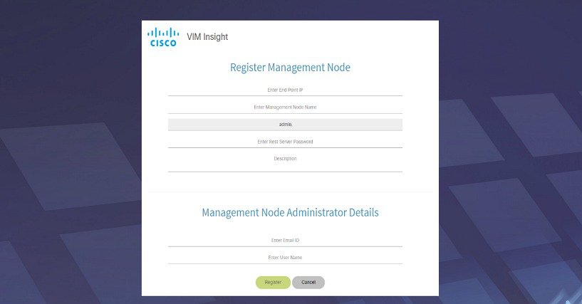
In this step the User registers a new pod to Insight. Pod registration includes the following steps:
Insight UI Admin needs to register a Pod Admin to allow the user to register a pod. Following are the steps required for UI Admin to register a Pod Admin:
Login to Insight as Pod Admin
To login to Insight as Pod Admin, complete the instructions below:
The VIM Insight UI
The VIM Insight UI is divided into four parts:
-
Dashboard
Dashboard of the VIM Installer provides the user an intuitive view of monitoring deployment. Dashboard provides a 3D view of 8 stages, which are present in the Installer CLI. The Carrousel displays the real-time status of the install steps, and it rotates automatically once an install stage is completed and a new install stage is started or scheduled. Dashboard maintains the pod state even when the User logs out. It will show the most recent data available via the VIM REST API on the management node. Dashboard provides the following rights to the administrator:
-
Deployed Blueprint Details: Shows information about the current Blueprint (Active/In-Progress). In case of an Inactive Blueprint, the table will be blank.
-
Deployment Status: This tells the status of the Blueprint. There are 3 stages of a Blueprint : Active, in-progress and Failed. Incase of in-progress and Failed states, the stage name would be mentioned in Deployment Status which is a hyperlink. If you click on the stage name, the carrousel will directly jump to that particular stage.
-
Deployment Started at: This tells the time when the installation was started.
-
Last Updated at: This tells the last updated time of the installation.
-
Click Here to check logs: If you click Here you will be redirected to the logs page in a new tab for which you will have to enter the REST Username and Password located at /opt/cisco/ui_config.json on the node. By default REST Username is "admin".
-
-
POD Operation Details: Displays the status regarding all the POD Activities done POST Installation like POD Management, Re-generate Secrets, etc. Following are the information shared in POD Operation Details table:
-
Blueprint Deployment Progress bar for a given POD: Shows the Blueprint success or failure state in percentage.
-
Switch Between Management Nodes: Will be covered later in this chapter.
Figure 2. VIM Insight Dashboard 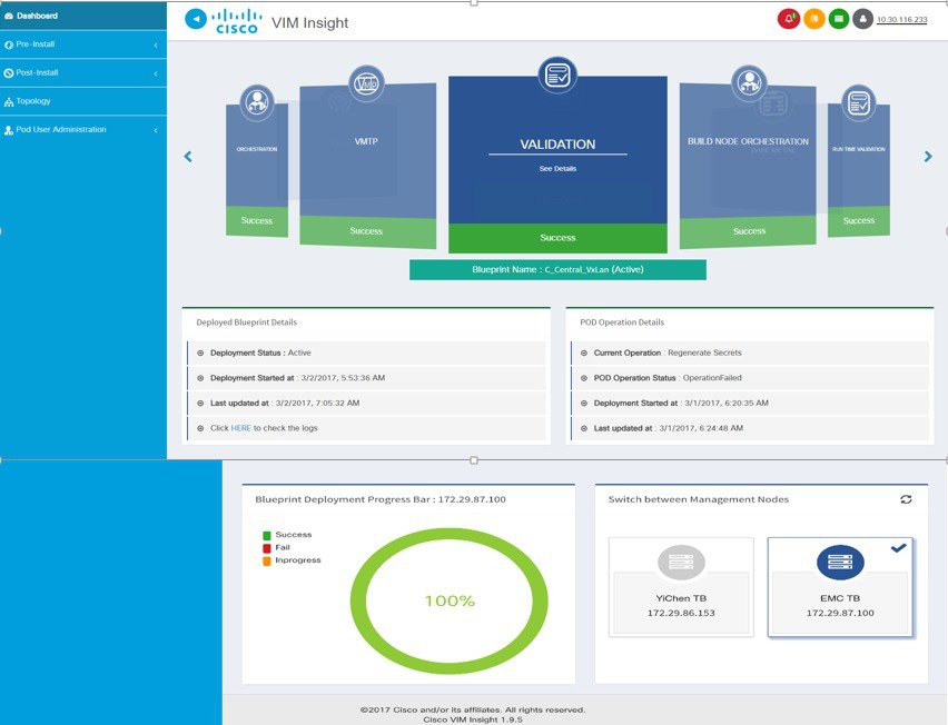
-
-
Pre-install
This section has two menus:
-
Blueprint Setup: Blueprint is the YAML (setupdata) present in the Management node. There are two ways to create a Blueprint:
In case of manual creation the user has to fill in details for Initial setup, physical setup and OpenStack, which covers core and optional features like VMTP, NFVI Monitoring, Auto configuration of ToR, Optional services like Heat, Keystonev3 and so on. In case of upload of an existing YAML, the user can just upload the file and click Upload to automatically populate all the corresponding fields in the UI. At any given point, one can initiate the offline validation of the entry, by clicking the Offline Validate button, on the upper right hand corner in the Blueprint Setup menu.
Offline Validation will only take place if all the fields marked in Blueprint are filled and there are no client side validations remaining. Even if they are the Offline Validation, pop up will show which field is missing.
Figure 3. Blueprint Creation 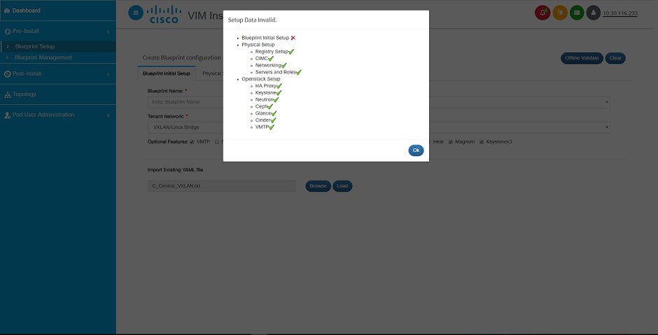
After filling all the details offline validation will take place, if successful, Save Blueprint option will be enabled, else user will not be allowed to save the Blueprint. Click Save blueprint to be redirected to Blueprint Management.
Figure 4. Blueprint Successful 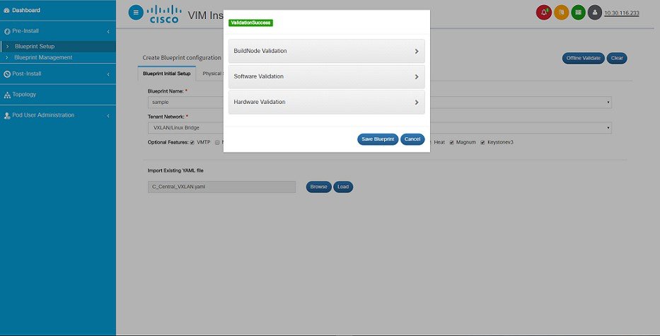
-
Blueprint Management:Blueprint Management gives CRUD access to users for Blueprints in the System. A user can use following features in Blueprint Management:
Figure 5. Blueprint Management 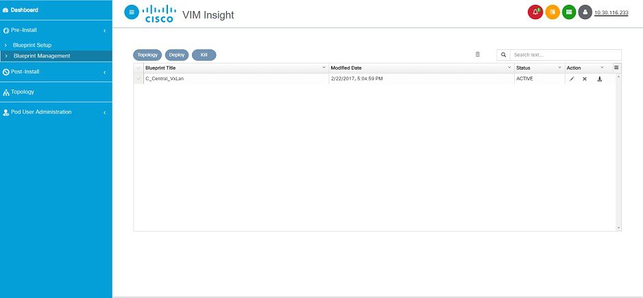
Figure 6. Blueprint Management Test 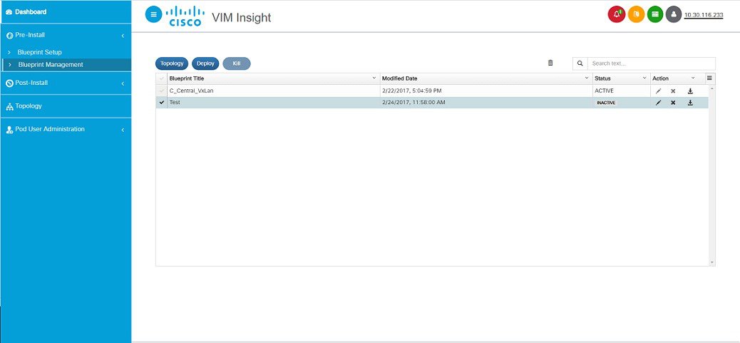
-
-
Post-install.
This section is active only when a Blueprint is in active state; that is if the install is successful, hence day-n operations are allowed.
-
Topology.
Topology is a logical representation of the Blueprint where it tells the user about the nodes connectivity with the respective networks and hardware information. Topology shows the active blueprints and user can select one among them.
Figure 7. Topology 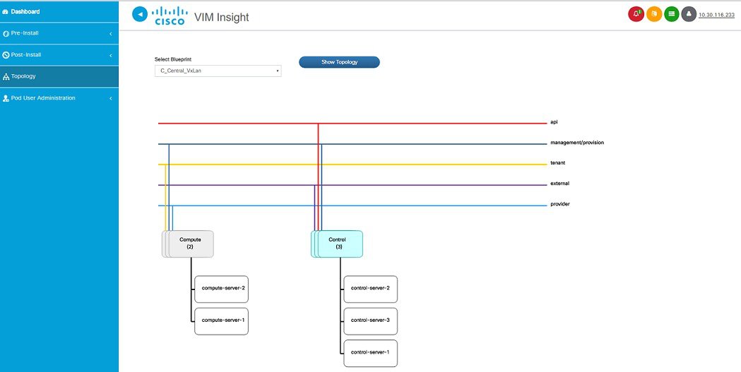
-
Pod User Administration
Pod User Administration menu is available only to admin of the Management Node. This admin can be default admin of the pod or users assigned with Pod Admin role by the default admin. It has two additional sub-panel options:
-
Manage Roles:
-
Manage Users:
-
Add/Edit/Delete Users.
-
List User name and Email ID for the users registered in the system.
-
Roles associated to users.
-
The current status of the user (Online and Offline user with Green and Red dot respectively).
-
User registration status.
-
Refresh button to get latest information about the users status.
Figure 9. Manage users 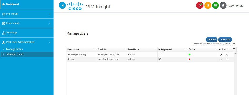
-
-
Context Switching within Insight
There are two ways that you can switch to another pod:
-
Context Switching Icon: Context Switching Icon is situated on the top right corner of the UI and is the second icon from the left tool tip. Click Management Node Context Switching, to access all pods. There can be a case when a pod has red dot right next to it which indicates that the REST Password provided during registration of Management node does not matches with the current REST Password for that particular node. The Pod Admin/User can reach out to UI Admin and ask them to update the password for that Node from Manage Nodes in Insight UI Admin Portal.
-
Switch Between Management Nodes: Switch Between Management Nodes is situated in Dashboard. You can navigate to the pods by a single click. If mouse changes from hand or cursor to a red not sign then it is the same case as mentioned above for the REST Password mismatch.
Configuring OpenStack Installation
You need to create a Blueprint (B or C Series) to initiate OpenStack Installation through the VIM.
Post Installation Features for Active Blueprint
This option is only available to a pod, which is successfully deployed. There are multiple sub-links available to manage the day-n operation of the pod. However, in many cases, Insight cross-launches the relevant services, thereby delegating the actual rendering to the individual services.
- Monitoring the Pod
- Cross Launching Horizon
- NFVI Monitoring
- Run VMTP
- Run CloudPulse
- Run NFV Bench
- Reconfiguring CIMC Password through Insight
- POD Management
- System Update
- Reconfigure Password
- Reconfigure Openstack Services, TLS certs and ELK configurations
- Reconfigure Optional Services
- Pod User Administration
Monitoring the Pod
VIM 2.2 uses ELK (elasticsearch, logstash and Kibana) to monitor the OpenStack services, by cross-launching the Kibana dashboard.
To cross launch Kibana, complete the following instructions:
| Step 1 | In the Navigation pane, click . The Authentication Required browser pop up is displayed. | ||
| Step 2 | Enter the username as admin. | ||
| Step 3 | Enter the
ELK_PASSWORD password obtained from
/root/installer-<tagid>/openstack-configs/secrets.yaml in the management
node.
Kibana
is launched in an I-Frame
|
Cross Launching Horizon
Horizon is the canonical implementation of Openstack's Dashboard, which provides a web based user interface to OpenStack services including Nova, Swift and, Keystone.
NFVI Monitoring
NFVI monitoring is a Cross launch browser same as Horizon. NFVI monitoring link is available in the post install only if the setupdata has NFVI Monitoring configuration during the cloud deployment which basically pings the monitoring and checks status of Collector VM1 Info and Collector VM2 Info.
Run VMTP
Run VMTP is divided in two sections:
-
Results for Auto Run: This will show the results of VMTP which was run during cloud deployment (Blueprint Installation).
-
Results for Manual Run: Here you have an option to run the VMTP on demand. To run VMTP on demand just click Run VMTP button.

Note
If VMTP stage was skipped/not-run during Blueprint Installation, this section of POST Install would be disabled for the user.
Run CloudPulse
Endpoints Tests:
Operator Tests:
Run NFV Bench
One can Run NFV Bench for BandC series Pod, through Cisco VIM Insight. On a pod running with CVIM 2.2, click on the NFVbench link on the NAV-Menu.
You can run either fixed rate test or NDR/PDR test. As the settings and results for the test types differ, the options to run these tests are presented in two tabs, with its own settings and results .
NDR/PDR Test
| Step 1 | Log-in to CISCO VIM Insight. | ||||||||
| Step 2 | In the Navigation pane, click Post-Install >Run NFV Bench. | ||||||||
| Step 3 | Click on NDR/PDR test and complete the following fields
|
Fixed Rate Test
| Step 1 | Log-in to CISCO VIM Insight. | ||||||||||
| Step 2 | In the Navigation pane, click Post-Install >Run NFV Bench. | ||||||||||
| Step 3 | Click on Fixed rate test and complete the following fields.
|
Reconfiguring CIMC Password through Insight
Update the cimc_password in the CIMC-COMMON section, and/or the individual cimc_password for each server and then run the update password option.
To update a password, you need to follow the password rules:
You must have a C-series pod up and running with Cisco VIM to reconfigure CIMC password.
Note | Reconfigure CIMC password section would be disabled if the pod is in failed state as indicated by ciscovim install-status. |
| Step 1 | Log-in to CISCO VIM Insight. | ||||||||
| Step 2 | In the navigation pane, select Post-Install | ||||||||
| Step 3 | Click Reconfigure CIMC Password. | ||||||||
| Step 4 | On the Reconfigure CIMC Password page of the Cisco VIM Insight,
complete the following fields:
|
POD Management
One of the key aspects of Cisco VIM is that it provides the ability for the admin to perform pod life-cycle management from a hardware and software perspective. Nodes of a given pod corrupts at times and VIM provides the ability to add, remove or replace nodes, based on the respective roles with some restrictions. Details of pod management will be listed in the admin guide, however as a summary the following operations are allowed on a running pod:
| Step 1 | Add or Remove Storage Nodes: You can add one node at a time, given that we run Ceph as a distributed storage offering. |
| Step 2 |
Add or Remove
Computes Nodes: N-computes nodes can be replaced simultaneously; however at
any given point, at least one compute node should be active.
|
| Step 3 |
Replace Control
Nodes: We do not support double fault scenarios, replacement of one
controller at a time is supported.
|
System Update
As part of the lifecycle management of the cloud, VIM has the ability to bring in patches (bug fixes related to code, security, etc.), thereby providing the additional value of seamless cloud management from software perspective. Software update of the cloud is achieved by uploading a valid tar file following initiation of a System Update from the Insight as follows:
| Step 1 | In the Navigation pane, click . |
| Step 2 | Click Browse button. |
| Step 3 | Select the valid tar file. |
| Step 4 | Click . Message stating System Update has been initiated will be displayed. Logs front-ended by hyperlink would be visible in the section below before Update Logs to help see the progress of the update. During the software update, all other pod management activities will be disabled. Post-update, normal cloud management will commence. |
Reconfigure Password
There are two options to regenerate the Password:
-
Regenerate all passwords: Click the checkbox of Regenerate all passwords and click Set Password. This will automatically regenerate all passwords in alphanumeric format.
-
Regenerate single or more password: If user wants to set a specific password for any service like Horizon's ADMIN_USER_PASSWORD they can add it by doing an inline edit. Double click on the filed under Password and then enter the password which will enable Set Password button.
Note | During the reconfiguration of password, all other pod management activities will be disabled. Post-update, normal cloud management will commence. |
Reconfigure Openstack Services, TLS certs and ELK configurations
Cisco VIM supports the reconfiguration of OpenStack log level services, TLS certificates, and ELK configuration. Listed below are the steps to reconfigure the OpenStack and other services:
| Step 1 | In the Navigation pane, click . |
| Step 2 | Click on the specific item to be changed and updated; For TLS certificate it is the path to certificate location. |
| Step 3 | Enter
Set Config
and the process will commence.
During the reconfiguration process, all other pod management activities will be disabled. Post-update, normal cloud management will commence. |
Reconfigure Optional Services
Cisco VIM offers optional services such as heat, migration to Keystone v3, NFVBench, NFVIMON and so on, that can be enabled as post-pod deployment. Optional services can be un-configured as post-deployment in 2.2 feature. These services can be enabled in one-shot or selectively. Listed below are the steps to enable optional services:
| Step 1 | In the Navigation pane, click . | ||||||||||||||||||||||||||||||||||||||||||||
| Step 2 | Choose the right service and update the fields with the right values. | ||||||||||||||||||||||||||||||||||||||||||||
| Step 3 | Enter
Reconfigure
to commence the process.
During the reconfiguration process, all other pod management activities will be disabled. Post-update, normal cloud management will commence. Once reconfigure is initiated than optional feature would be updated in active blueprint. If reconfigure of Optional Services fail in the time of reconfigure process then it is advised to contact CiscoTAC to resolve the situation through CLI.
Deployment Status :
|
Pod User Administration
Cisco VIM Insight offers Users (Pod Admin(s) or Pod Users) to manage Users and roles associated with them.
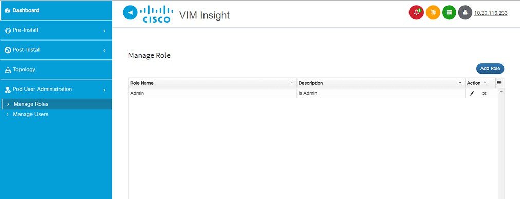
Managing Roles
To create a new Role
| Step 1 | Click Login as POD User. | ||||||||
| Step 2 | Navigate to Pod User Administration and click Manage Roles. By default you will see full-pod-access role in the table. | ||||||||
| Step 3 | Click Add Role to create a new role. | ||||||||
| Step 4 | Complete the
following fields in the
Add Roles
page in Cisco VIM Insight:
| ||||||||
| Step 5 | Click
Save. Once the Blueprint is in Active state all the
permissions are same for C-series and B-series Pods other than Reconfigure CIMC
Password which is missing for B-series Pod.
|
Managing Users
To add new User
| Step 1 | Click Login as POD User. | ||||||||
| Step 2 | Navigate to POD User Administration. | ||||||||
| Step 3 | Click Manage Users. | ||||||||
| Step 4 | Click Add Users to add a new user. | ||||||||
| Step 5 | Complete the
following fields in the
Add
Users page of the Cisco VIM Insight:
| ||||||||
| Step 6 | Click Save. |
Managing Root CA Certificate
You can update the CA Certificate during the registration of the POD. Once, logged in as POD User and if you have the permission to update the certificate you can view under POD User Administration>> Manage Root CA Certificate.
To update the Certificate:
| Step 1 | Click Login as POD User | ||
| Step 2 | Navigate to POD User Administration>>Manage Root CA certificate. | ||
| Step 3 | Click Browse and select the certificate that you want to upload. | ||
| Step 4 | Click Upload.
|
 Feedback