- Overview to Cisco NFVI
- Cisco NFVI Installation Overview
- Preparing for Installation on Servers Without Internet Access
- Preparing for Cisco NFVI Installation
- Installing Cisco VTS
- Installing Cisco VIM
- Installing Cisco VIM Insight
- Installing Cisco VIM through Cisco VIM Insight
- Verifying the Cisco NFVI Installation
- Installing the Cisco NFVI Hardware
- Configuring ToR Switches for C-Series Pods
- Configuring ToR Switches for UCS B-Series Pods
- Preparing Cisco IMC and Cisco UCS Manager
- Installing the Management Node
- Setting Up the UCS C-Series Pod
- Setting Up the UCS B-Series Pod
- Configuring the Out-of-Band Management Switch
Preparing for Cisco NFVI Installation
Before you can install and configure Cisco NFVI, you must complete the following hardware and application preparation procedures provided in the following topics.
- Installing the Cisco NFVI Hardware
- Configuring ToR Switches for C-Series Pods
- Configuring ToR Switches for UCS B-Series Pods
- Preparing Cisco IMC and Cisco UCS Manager
- Installing the Management Node
- Setting Up the UCS C-Series Pod
- Setting Up the UCS B-Series Pod
- Configuring the Out-of-Band Management Switch
Installing the Cisco NFVI Hardware
The Cisco UCS C-Series or B-Series hardware must be powered up, before you can install the Cisco Virtualization Infrastructure Manager (VIM). Depending upon the pod type, the CIMC connection or UCSM IP has to be configured ahead of time.The following table lists the UCS hardware options and network connectivity protocol that can be used with each, either virtual extensible LAN (VXLAN) over a Linux bridge, VLAN over OVS or VLAN over VPP. If Cisco Virtual Topology Services, an optional Cisco NFVI application, is installed, Virtual Topology Forwarder (VTF) can be used with VXLAN for tenants, and VLANs for providers on C-Series pods.
|
UCS Pod Type |
Compute and Controller Node |
Storage Node |
Network Connectivity Protocol |
|---|---|---|---|
|
C-Series |
UCS C220/240 M4. |
UCS C240 M4 (SFF) with two internal SSDs. |
VXLAN/Linux Bridge or OVS/VLAN or VPP/VLAN, or ACI/VLAN. |
|
C-Series with Cisco VTS |
UCS C220/240 M4. |
UCS C240 M4 (SFF) with two internal SSDs. |
For tenants: VTF with VXLAN. For providers: VLAN |
|
C-Series Micro Pod |
UCS 240 M4 with 12 HDD and 2 external SSDs. |
Not Applicable as its integrated with Compute and Controller. |
OVS/VLAN or VPP/VLAN or ACI/VLAN. |
|
C-Series Hyperconverged |
UCS 240 M4. |
UCS C240 M4 (SFF) with 12 HDD and two external SSDs, also acts a compute node. |
OVS/VLAN |
|
B-Series |
UCS B200 M4. |
UCS C240 M4 (SFF) with two internal SSDs. |
VXLAN/Linux Bridge or OVS/VLAN. |
|
B-Series with UCS Manager Plugin |
UCS B200 M4s |
UCS C240 M4 (SFF) with two internal SSDs. |
OVS/VLAN |
 Note | The storage nodes boot off two internal SSDs. It also has four external solid state drives (SSDs) for journaling, which gives a 1:5 SSD-to-disk ratio (assuming a chassis filled with 20 spinning disks). Each C-Series pod has either a 2 port 10 GE Cisco vNIC 1227 card or 2 of 4 port Intel 710 X card. UCS M4 blades only support Cisco 1340 and 1380 NICs. For more information about Cisco vNICs, see LAN and SAN Connectivity for a Cisco UCS Blade. Cisco VIM has a micro pod which works on Cisco VIC 1227 or Intel NIC 710, with OVS/VLAN as the virtual network protocol. The micro pod supports customers with a small, functional, but redundant cloud. The current manifestation of the micro-pod works on Cisco VIC (1227) or Intel NIC 710, with OVS/VLAN of VPP/VLAN as the virtual network protocol. |
In addition, the Cisco Nexus 9372 or 93180YC, or 9396PX must be available to serve the Cisco NFVI ToR function .
After verifying that you have the required Cisco UCS servers and blades and the Nexus 93xx, install the hardware following procedures at the following links:
The figure below shows a C-Series Cisco NFVI pod. Although the figure shows a full complement of UCS C220 compute nodes, the number of compute nodes can vary, depending on your implementation requirements. The UCS C220 control and compute nodes can be replaced with UCS 240 series. However in that case the number of computes fitting in one chassis system will be reduced by half.
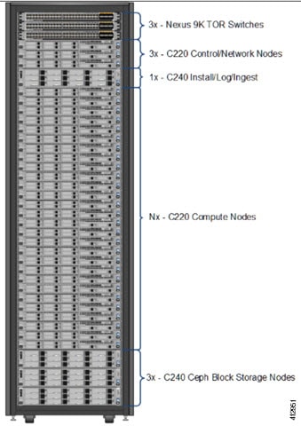
Note | The combination of UCS-220 and 240 within the compute and control nodes is not supported. |
Configuring ToR Switches for C-Series Pods
During installation, the Cisco VIM installer creates vNIC's on each of the two physical interfaces and creates a bond for the UCS C-Series pod. Before this occurs, you must manually configure the ToR switches to create a vPC with the two interfaces connected to each server. Use identical Cisco Nexus 9372 , or 93180YC, or 9396PX switches for the ToRs. We recommend you to use the N9K TOR software versions for setup: 7.0(3)I4(6) 7.0(3)I6(1).
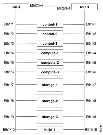
Complete the following steps to create a vPC on a pair of Cisco Nexus ToR switches. The steps will use the following topology as an example. Modify the configuration as it applies to your environment. In Cisco VIM, we have introduced a feature called auto-configuration of ToR (for N9K series only). This is an optional feature, and if you decide to take this route, the following steps can be skipped.
Configuring ToR Switches for UCS B-Series Pods
Complete the following steps to create a vPC on a pair of Cisco Nexus ToR switches for a UCS B-Series pod. The steps are similar to configuring ToR switches for C-Series pods, with some differences. In the steps, the two ToR switches are Storm-tor-1 (mgmt0 is 172.18.116.185), and Storm-tor-2 (mgmt0 is 172.18.116.186). Modify the configuration as it applies to your environment. If no multicast or QOS configuration is required, and Auto-configuration of TOR is chosen as an option, the steps listed below can be skipped.
| Step 1 | Change the vPC
domain ID for your configuration. The vPC domain ID can be any number as long
as it is unique. The IP address on the other switch mgmt0 port is used for the
keepalive IP. Please change it to the IP used for your network. Storm-tor-1
(mgmt0 is 172.18.116.185)
feature vpc
vpc domain 116
peer-keepalive destination 172.18.116.186
for each vlan_type (mgmt_vlan, tenant_vlan_range, storage, api, external, provider); # execute the following for each vlan
vlan <vlan_type>
    no shut
vrf context management
ip route 0.0.0.0/0 172.18.116.1
interface mgmt0
vrf member management
ip address 172.18.116.185/24
Storm-tor-2 (mgmt0 is 172.18.116.186) feature vpc
vpc domain 116
peer-keepalive destination 172.18.116.185
for each vlan_type (mgmt_vlan, tenant_vlan_range, storage, api, external, provider); # execute the following for each vlan
vlan <vlan_type>
no shut
vrf context management
ip route 0.0.0.0/0 172.18.116.1
interface mgmt0
vrf member management
ip address 172.18.116.186/24
| ||
| Step 2 | Since both
switches are cabled identically, the rest of the configuration is identical on
both switches. Configure all the interfaces connected to the fabric
interconnects to be in the VPC as well.
feature lacp
interface port-channel1
     description “to fabric interconnect 1”
     switchport mode trunk
     vpc 1
interface port-channel2
     description “to fabric interconnect 2”
     switchport mode trunk
     vpc 2
interface Ethernet1/43
     description "to fabric interconnect 1"
     switchport mode trunk
     channel-group 1 mode active
interface Ethernet1/44
     description "to fabric interconnect 2"
     switchport mode trunk
     channel-group 2 mode active
| ||
| Step 3 | Create the
port-channel interface on the ToR that is connecting to the management node:
interface port-channel3
     description “to management node”
     spanning-tree port type edge trunk
     switchport mode trunk
     switchport trunk allowed vlan <mgmt_vlan>
     no lacp suspend-individual
     vpc 3
interface Ethernet1/2
     description "to management node"
     switchport mode trunk
     channel-group 3 mode active
| ||
| Step 4 | Enable jumbo
frames for each ToR port-channel that connects to the Fabric Interconnects:
interface port-channel<number>
     mtu 9216
|
Preparing Cisco IMC and Cisco UCS Manager
Cisco NFVI requires specific Cisco Integrated Management Controller (IMC) and Cisco UCS Manager firmware versions and parameters. The Cisco VIM bare metal installation uses the Cisco IMC credentials to access the server Cisco IMC interface, which you will use to delete and create vNICS and to create bonds. Complete the following steps to verify Cisco IMC and UCS Manager are ready for Cisco NFVI installation:
| Step 1 | Verify that each Cisco UCS server has one of the following Cisco IMC firmware versions is running 2.0(13i) or greater. Cisco IMC version cannot be 3.0 series. The latest Cisco IMC ISO image can be downloaded from the Cisco Software Download site. For upgrade procedures, see the Cisco UCS C-Series Rack-Mount Server BIOS Upgrade Guide. |
| Step 2 | For UCS B-Series pods, verify that the Cisco UCS Manager version is one of the following: 2.2(5a), 2.2(5b), 2.2(6c), 2.2(6e), 3.1(c). |
| Step 3 | For UCS C-Series pods, verify the following Cisco IMC information is added: IP address, username, and password. |
| Step 4 | For UCS B-Series pods, verify the following UCS Manager information is added: username, password, IP address, and resource prefix. The resource prefix maximum length is 6. The provisioning network and the UCS Manager IP address must be connected. |
| Step 5 | Verify that no legacy DHCP/Cobbler/PXE servers are connected to your UCS servers. If so, disconnect or disable the interface connected to legacy DHCP, Cobbler, or PXE server. Also, delete the system from the legacy cobbler server. |
| Step 6 | Verify Cisco IMC has NTP enabled and is set to the same NTP server and time zone as the operating system. |
Installing the Management Node
This procedures installs RHEL 7.4 with the following modifications:
-
Hard disk drives are setup in RAID 6 configuration with one spare HDD for eight HDDs deployment, two spare HDDs for 9 to 16 HDDs deployment, or four spare HDDs for 17 to 24 HDDs deployment
-
Networking—Two bridge interfaces are created, one for the installer API and one for provisioning. Each bridge interface has underlying interfaces bonded together with 802.3ad. Provision interfaces are 10 GE Cisco VICs. API interfaces are 1 GE LOMs. If the NFVIBENCH, is palnned to be used, another 2xIntel 520 or 4xIntel710 X is needed.
-
The installer code is placed in /root/.
-
SELinux is enabled on the management node for security.
Verify that the Cisco NFVI management node where you plan to install the Red Hat for Enterprise Linux (RHEL) operating system is a Cisco UCS C240 M4 Small Form Factor (SFF) with 8, 16 or 24 hard disk drives (HDDs). In addition, the management node must be connected to your enterprise NTP and DNS servers. If your management node server does not meet these requirements, do not continue until you install a qualified UCS C240 server. Also, verify that the pod has MRAID card.
| Step 1 | Log into the Cisco NFVI management node. | ||
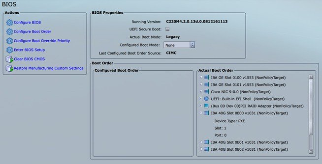
| Step 2 | Follow steps in Configuring the Server Boot Order to set the boot order to boot from Local HDD. | ||
| Step 3 | Follow steps in
Cisco UCS
Configure BIOS
Parameters to set the following advanced BIOS settings:
| ||
| Step 4 | Click Save Changes. | ||
| Step 5 | Add the
management node vNICs to the provisioning VLAN to provide the management node
with access to the provisioning network:
| ||
| Step 6 | Download the Cisco VIM ISO image to your computer from the location provided to you by the account team. | ||
| Step 7 | In CIMC, launch the KVM console. | ||
| Step 8 | Mount the Cisco VIM ISO image as a virtual DVD. | ||
| Step 9 | Reboot the UCS server, then press F6 to enter the boot menu. | ||
| Step 10 | Select the KVM-mapped DVD to boot the Cisco VIM ISO image supplied with the install artifacts. | ||
| Step 11 | When the boot menu appears, select Install Cisco VIM Management Node. This is the default selection, and will automatically be chosen after the timeout. | ||
| Step 12 | At the prompts,
enter the following parameters:
After you enter the management node IP addresses, the Installation options menu appears. Be careful when entering options, below. In the installation menu, there are more options,only fill in the options listed below (option8 and 2) and leave everything else as it is. If there is problem to start the installation, enter"r" to refresh the Installation menu. | ||
| Step 13 | In the Installation menu, select option 8 to enter the root password. | ||
| Step 14 | At the password prompts, enter the root password, then enter it again to confirm. | ||
| Step 15 | At the Installation Menu, select option 2 to enter the time zone. | ||
| Step 16 | At the Timezone settings prompt, enter the number corresponding to your time zone. | ||
| Step 17 | At the next prompt, enter the number for your region. | ||
| Step 18 | At the next prompt, choose the city, then confirm the time zone settings. | ||
| Step 19 | After confirming your time zone settings, enter b to start the installation. | ||
| Step 20 | After the installation is complete, press Return to reboot the server. | ||
| Step 21 | After the
reboot, check the management node clock using the Linux
date
command to ensure the TLS certificates are valid, for example:
#date Mon Aug 22 05:36:39 PDT 2016 To set date: #date -s '2016-08-21 22:40:00' Sun Aug 21 22:40:00 PDT 2016 To check for date: #date Sun Aug 21 22:40:02 PDT 2016 |
Setting Up the UCS C-Series Pod
After you install the RHEL OS on the management node, perform the following steps to set up the Cisco UCS C-Series servers:
| Step 1 | Follow steps in Configuring the Server Boot Order to set the boot order to boot from Local HDD. |
| Step 2 | Follow steps
in Configure BIOS Parameters to set the LOM, HBA, and PCIe slots to the
following settings:
mkdir -p /tmp/Intel/ tar xvf PREBOOT.tar -C /tmp/Intel/ cd /tmp/Intel/ cd APPS/BootUtil/Linux_x64 chmod a+x bootutili64e ./bootutili64e –h # help ./bootutili64e # list out the current settings for NIC ./bootutili64e -bootenable=pxe -all shutdown -r now # now go with PXE # Check result of the flash utility (watch out for PXE Enabled on 40GbE interface) #./bootutil64e Intel(R) Ethernet Flash Firmware Utility BootUtil version 1.6.20.1 Copyright (C) 2003-2016 Intel Corporation Type BootUtil -? for help Port Network Address Location Series WOL Flash Firmware Version ==== =============== ======== ======= === ============================= ======= 1 006BF10829A8 18:00.0 Gigabit YES UEFI,CLP,PXE Enabled,iSCSI 1.5.53 2 006BF10829A8 18:00.1 Gigabit YES UEFI,CLP,PXE Enabled,iSCSI 1.5.53 3 3CFDFEA471F0 10:00.0 40GbE N/A UEFI,CLP,PXE Enabled,iSCSI 1.0.31 4 3CFDFEA471F1 10:00.1 40GbE N/A UEFI,CLP,PXE Enabled,iSCSI 1.0.31 5 3CFDFEA471F2 10:00.2 40GbE N/A UEFI,CLP,PXE,iSCSI ------- 6 3CFDFEA471F3 10:00.3 40GbE N/A UEFI,CLP,PXE,iSCSI ------- 7 3CFDFEA47130 14:00.0 40GbE N/A UEFI,CLP,PXE Enabled,iSCSI 1.0.31 8 3CFDFEA47131 14:00.1 40GbE N/A UEFI,CLP,PXE Enabled,iSCSI 1.0.31 9 3CFDFEA47132 14:00.2 40GbE N/A UEFI,CLP,PXE,iSCSI ------- 10 3CFDFEA47133 14:00.3 40GbE N/A UEFI,CLP,PXE,iSCSI ------- # |
Setting Up the UCS B-Series Pod
After you install the RHEL OS on the management node, complete the following steps to configure a Cisco NFVI B-Series pod:
| Step 1 | Log in to Cisco UCS Manager, connect to the console of both fabrics and execute the following commands: |
| Step 2 | # connect local-mgmt # erase config All UCS configurations will be erased and system will reboot. Are you sure? (yes/no): yes Removing all the configuration. Please wait…. |
| Step 3 | Go through the
management connection and clustering wizards to configure Fabric A and Fabric
B:
Fabric Interconnect A # connect local-mgmt # erase config Enter the configuration method. (console/gui) console Enter the setup mode; setup newly or restore from backup. (setup/restore) ? setup You have chosen to setup a new Fabric interconnect. Continue? (y/n): y Enforce strong password? (y/n) [y]: n Enter the password for "admin": Confirm the password for "admin": Is this Fabric interconnect part of a cluster(select 'no' for standalone)? (yes/no) [n]: yes Enter the switch fabric (A/B) []: A Enter the system name: skull-fabric Physical Switch Mgmt0 IPv4 address : 10.30.119.58 Physical Switch Mgmt0 IPv4 netmask : 255.255.255.0 IPv4 address of the default gateway : 10.30.119.1 Cluster IPv4 address : 10.30.119.60 Configure the DNS Server IPv4 address? (yes/no) [n]: y DNS IPv4 address : 172.29.74.154 Configure the default domain name? (yes/no) [n]: y Default domain name : ctocllab.cisco.com Join centralized management environment (UCS Central)? (yes/no) [n]: n Following configurations will be applied: Switch Fabric=A System Name=skull-fabric Enforced Strong Password=no Physical Switch Mgmt0 IP Address=10.30.119.58 Physical Switch Mgmt0 IP Netmask=255.255.255.0 Default Gateway=10.30.119.1 DNS Server=172.29.74.154 Domain Name=ctocllab.cisco.com Cluster Enabled=yes Cluster IP Address=10.30.119.60 NOTE: Cluster IP will be configured only after both Fabric Interconnects are initialized Apply and save the configuration (select 'no' if you want to re-enter)? (yes/no): yes Applying configuration. Please wait.. Fabric Interconnect B Enter the configuration method. (console/gui) ? console Installer has detected the presence of a peer Fabric interconnect. This Fabric interconnect will be added to the cluster. Continue (y/n) ? y Enter the admin password of the peer Fabric interconnect: Connecting to peer Fabric interconnect... done Retrieving config from peer Fabric interconnect... done Peer Fabric interconnect Mgmt0 IP Address: 10.30.119.58 Peer Fabric interconnect Mgmt0 IP Netmask: 255.255.255.0 Cluster IP address : 10.30.119.60 Physical Switch Mgmt0 IPv4 address : 10.30.119.59 Apply and save the configuration (select 'no' if you want to re-enter)? (yes/no): yes Applying configuration. Please wait. |
| Step 4 | Configure the
NTP:
|
| Step 5 | Following instructions in Cisco UCS Manager GUI Configuration Guide, Release 2.2, "Configuring Server Ports with the Internal Fabric Manager" section, configure the Fabric Interconnect A and Fabric Interconnect B uplinks to the Cisco NFVI top of rack (ToR) switches as Uplink Ports, Server Ports, and Port Channels. |
| Step 6 | Configure the downlinks to the B-Series server chassis as Server Ports. |
| Step 7 | Acknowledge all chassis. |
Configuring the Out-of-Band Management Switch
The Cisco VIM installer API and SSH bonded interface occurs on 1 GB Intel NICs that connect the Cisco NFVI management node and the Cisco Catalyst switch. Following is a sample configuration for creating a port channel on a Catalyst switch. Modify the configuration for your environment:
interface GigabitEthernet0/39
 channel-group 2 mode active
 speed 1000

interface GigabitEthernet0/40
 channel-group 2 mode active
 speed 1000

interface Port-channel2
 switchport access vlan 165
 switchport mode access
 Feedback