- About This Guide
- Introducing the Cisco Prime NAM 2300 Series Appliances
- Installing the Cisco Prime NAM 2300 Series Appliances
- Configuring the Cisco Prime NAM 2300 Series Appliances
- Installing and Configuring External Storage
- Maintaining the Cisco Prime NAM 2300 Series Appliances
- Upgrading NAM Software
- Troubleshooting
- Safety Guidelines
- Specifications for the 2300 series appliances
- Site Log
- Helper Utility
- Index
Installing the Cisco Prime NAM 2300 Series Appliances
This chapter provides the information you need to install your Cisco Prime NAM 2300 series appliances, including how to install hardware options, how to mount the NAM appliance in a rack, cabling, and how to connect it to the network.
These instructions are intended for technicians who are experienced with installing, replacing, and removing the hardware components from electronic devices and are familiar with the Cisco Prime NAM 2300 series appliances. Additionally, site planners, network administrators, and facility maintenance personnel might also find this informatiofn helpful.
The installation and replacement of the hardware components of the Cisco Prime NAM 2300 series appliances involve many steps, most of which must be done in the order in which they are presented here. Each section explains one associated group of tasks upon which the next section’s tasks are built.
Requirements and Restrictions
This section contains the requirements that are necessary for the product to run successfully:
- Plan your site configuration and prepare the site before installing the appliance. Cisco Prime NAM 2300 series appliances come preinstalled on either a Cisco UCS C220 or C240 server, so for the recommended site planning tasks, see the Cisco UCS Site Preparation Guide.
- For physical, environmental, and power requirements, including thermal (air conditioning), space, and power requirements, see Appendix C, “Technical Specifications” . If available, you can use an uninterruptible power supply (UPS) to protect against power failures.

- Ensure that the cabinet or rack meets the requirements listed in the section, see Install the Appliance in a Rack.
Installation Process Summary
This section provides a summary of how to prepare and install the Cisco Prime NAM 2300 series appliances.

Warning![]() Read the installation instructions before connecting the system to the power source. Statement 1004
Read the installation instructions before connecting the system to the power source. Statement 1004
|
|
|
Warning![]() Only trained and qualified personnel should be allowed to install, replace, or service this equipment. Statement 1030
Only trained and qualified personnel should be allowed to install, replace, or service this equipment. Statement 1030
Warning![]() This unit is intended for installation in restricted access areas. A restricted access area can be accessed only through the use of a special tool, lock and key, or other means of security.
This unit is intended for installation in restricted access areas. A restricted access area can be accessed only through the use of a special tool, lock and key, or other means of security.
Statement 1017
Warning![]() Power off the unit before you begin. Statement 237
Power off the unit before you begin. Statement 237
Warning![]() To prevent personal injury or damage to the chassis, never attempt to lift or tilt the chassis using the handles on modules (such as power supplies, fans, or cards); these types of handles are not designed to support the weight of the unit. Statement 1032
To prevent personal injury or damage to the chassis, never attempt to lift or tilt the chassis using the handles on modules (such as power supplies, fans, or cards); these types of handles are not designed to support the weight of the unit. Statement 1032
Warning![]() Do not touch the power supply when the power cord is connected. For systems with a power switch, line voltages are present within the power supply even when the power switch is off and the power cord is connected. For systems without a power switch, line voltages are present within the power supply when the power cord is connected. Statement 4
Do not touch the power supply when the power cord is connected. For systems with a power switch, line voltages are present within the power supply even when the power switch is off and the power cord is connected. For systems without a power switch, line voltages are present within the power supply when the power cord is connected. Statement 4
Step 2![]() Unpack and inspect each of the components for possible damage that might have occurred during shipping. Ensure that you have all required components.
Unpack and inspect each of the components for possible damage that might have occurred during shipping. Ensure that you have all required components.
See Unpack and Inspect the Appliance.
Step 3![]() Install the Cisco Prime NAM 2300 series appliance in a rack.
Install the Cisco Prime NAM 2300 series appliance in a rack.
See Install the Appliance in a Rack.
Step 4![]() Install the transceiver modules.
Install the transceiver modules.
See Install the Transceiver Modules.
Step 5![]() Connect the appliance to a power source.
Connect the appliance to a power source.
See Connect the Power.
Step 6![]() Connect the appliance cables.
Connect the appliance cables.
See Connect the Appliance Cables
After completing the hardware installation, configure the appliance. See Chapter3, “Configuring the Cisco Prime NAM 2300 Series Appliances”
Unpack and Inspect the Appliance

Tip![]() Do not remove the appliance from its shipping container until you are ready to install it.
Do not remove the appliance from its shipping container until you are ready to install it.
Tip![]() Do not discard the packaging materials used in shipping your Cisco Prime NAM 2300 series appliance. You will need the packaging materials in the future if you move or ship your appliance.
Do not discard the packaging materials used in shipping your Cisco Prime NAM 2300 series appliance. You will need the packaging materials in the future if you move or ship your appliance.

Note![]() The chassis is thoroughly inspected before shipment. If any damage occurred during transportation or any items are missing, contact your customer service representative immediately.
The chassis is thoroughly inspected before shipment. If any damage occurred during transportation or any items are missing, contact your customer service representative immediately.
To unpack and inspect the shipment:
Step 1![]() Remove the appliance from its cardboard container and save all packaging material.
Remove the appliance from its cardboard container and save all packaging material.
Step 2![]() Compare the shipment to the equipment list. Verify that you have all items.
Compare the shipment to the equipment list. Verify that you have all items.
The appliance, cables, and any optional equipment you ordered might be shipped in more than one container. When you unpack the containers, check the items against the packing list (see Table 2-1 and Table 2-2 ) to verify that you received all the parts.
Step 3![]() Check for damage and report any discrepancies or damage to your customer service representative. Have the following information ready:
Check for damage and report any discrepancies or damage to your customer service representative. Have the following information ready:
- Invoice number of shipper (see the packing slip)
- Model and serial number (see Serial Number Locations) of the damaged unit
- Description of damage
- Effect of damage on the installation
Cisco Prime NAM 2304 Appliance Packing List
The following table lists the items that ship with the Cisco Prime NAM 2304 appliance. A Notes section has been provided to record damaged or missing items.

|
|
|---|---|

|
Cisco Prime NAM 2304 appliance, pre-installed on a Cisco UCS C220 server |
|
|
|
|
|
|
|
|
|
|
|
CABASY, RF, MICRO MINITURE, FOX 36P, 9P DSUB, USB, DONGLE CABLE |
|
|
|
|
|
|
|
|
|
Cisco Prime NAM 2320 Appliance Packing List
The following table lists the items that ship with the Cisco Prime NAM 2320 appliance. A Notes section has been provided to record damaged or missing items.
|
|
|
|---|---|
|
|
Cisco Prime NAM 2320 appliance, pre-installed on a Cisco C240 server |
|
|
|
|
|
|
|
|
|
|
|
CABASY, RF, MICRO MINITURE, FOX 36P, 9P DSUB, USB, DONGLE CABLE |
|
|
|
|
|
|
|
|
|
Install the Appliance in a Rack
The rack must be of the following type:
- A standard 19-in. (48.3-cm) wide, four-post EIA rack, with mounting posts that conform to English universal hole spacing, per section 1 of ANSI/EIA-310-D-1992.
- The rack post holes can be square.38-inch (9.6 mm), round.28-inch (7.1 mm), #12-24 UNC, or #10-32 UNC when you use the supplied slide rails.
- The minimum vertical rack space per appliance must be two RUs, equal to 3.5 in. (88.9 mm).
The slide rails supplied by Cisco Systems for this appliance do not require tools for installation. The inner rails (mounting brackets) are pre-attached to the sides of the appliance.
Because the Cisco Prime NAM 2300 series appliances come pre-installed on a Cisco UCS C220 or C240 server, see the following UCS installation guides for the recommended rack mounting tasks:
|
|
|
|---|---|
The Installing the Server In a Rack section in the Cisco UCS C220 Server Installation and Service Guide. |
|
The Installing the Server In a Rack section in the Cisco UCS C240 Server Installation and Service Guide. |
Install the Transceiver Modules
You can order SFP or SFP+ transceiver modules as hardware options or you can use modules you might already own as long as they meet the specifications described in the data sheets on Cisco.com. Because these modules are delicate devices, they are packaged separately and are not installed in the appliance prior to shipping.
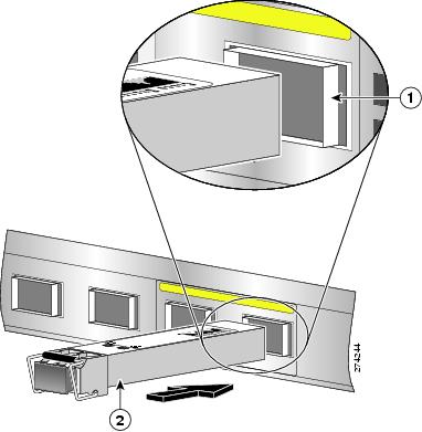
Figure 2-1 shows a detailed view of an SFP+ module installation.
Figure 2-1 Installing an SFP+ Module
|
|
|
To install an SFP or SFP+ module in a Cisco Prime NAM 2300 series appliance:
Step 1![]() Locate the transceiver module you plan to install and remove any protective packaging.
Locate the transceiver module you plan to install and remove any protective packaging.
Step 2![]() Determine into which of the two slots on the rear panel of the NAM appliance (see Figure 1-2 on page 1-4 and Figure 1-4 on page 1-5) you will install the module.
Determine into which of the two slots on the rear panel of the NAM appliance (see Figure 1-2 on page 1-4 and Figure 1-4 on page 1-5) you will install the module.
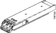
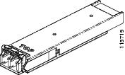
The SFP and SFP+ modules use the bail clasp latching mechanism as shown unlatched in Figure 2-2 and latched in Figure 2-3.
Step 3![]() With its latch open, slide the module into the slot until you feel resistance, then push it harder until you feel (or hear) it click into its socket.
With its latch open, slide the module into the slot until you feel resistance, then push it harder until you feel (or hear) it click into its socket.
Figure 2-2 shows an example of a transceiver module with its latch open.
Figure 2-2 Transceiver Module (unlatched)
Step 4![]() With your finger, pull the latch upwards to lock the module into its slot.
With your finger, pull the latch upwards to lock the module into its slot.
Figure 2-3 Transceiver Module (latched)
Step 5![]() Plug in the fiber optical cable.
Plug in the fiber optical cable.
Step 6![]() Observe the front-panel LEDs to verify that the connection is operating properly. (See “Reading the LEDs” section.)
Observe the front-panel LEDs to verify that the connection is operating properly. (See “Reading the LEDs” section.)
To replace a transceiver module, see Replacing Transceiver Modules.
Connect the Power
When installing the NAM appliance, use the AC power cord that was shipped with the Cisco Prime NAM 2300 series appliance.
The AC power cord is considered the primary disconnect for the appliance and must be readily accessible when installed. If the appliance power cord is not readily accessible to be disconnected, you must install an AC power disconnect for the entire rack. This disconnect must be readily accessible, and it must be properly labeled as the controlling power to the entire rack, not just to the appliance.
To connect the AC power to the Cisco Prime NAM 2300 series appliance:
Step 1![]() Review the Safety with Electricity information in the Safety Guidelines appendix.
Review the Safety with Electricity information in the Safety Guidelines appendix.
To avoid the potential for an electrical shock, you must include a third wire safety ground conductor with the rack installation. If the appliance power cord is plugged into an AC outlet that is part of the rack, you must provide proper grounding for the rack itself. If the appliance power cord is plugged into a wall outlet, the safety ground conductor in the power cord provides proper grounding only for the appliance. You must provide additional, proper grounding for the rack.
Step 3![]() Plug the AC power cord into the AC power input connector at the rear of the appliance (see Figure 1-2 and Figure 1-4), and the other end of the power cord to a power source at your site.
Plug the AC power cord into the AC power input connector at the rear of the appliance (see Figure 1-2 and Figure 1-4), and the other end of the power cord to a power source at your site.
The AC power cord is considered the primary disconnect for the appliance and must be readily accessible when installed. If the appliance power cord is not readily accessible to be disconnected, you must install an AC power disconnect for the entire rack. This disconnect must be readily accessible, and it must be properly labeled as the controlling power to the entire rack, not just to the appliance.
Connect the Appliance Cables
This section describes how to connect cables to your Cisco Prime NAM 2300 series appliance. It includes the following topics:
- Connect the Management Port
- Connect the Monitoring Ports
- Connect a Console Terminal
- Connect a Monitor to the Appliance
Connect the Management Port
The Cisco Prime NAM 2300 series appliance management port is the LAN 1 port (see Figure 1-2 on page 1-4 and Figure 1-4 on page 1-5), an RJ-45 10BASE-T/100BASE-TX/1000BASE-T network interface connector.
To connect the Cisco Prime NAM 2204 appliance management port:
Step 1![]() Connect one end of a Cat5e (or better) UTP cable to the LAN 1 port on the appliance.
Connect one end of a Cat5e (or better) UTP cable to the LAN 1 port on the appliance.
Step 2![]() Connect the other end of the cable to a hub or switch (a gateway) in your network.
Connect the other end of the cable to a hub or switch (a gateway) in your network.
Step 3![]() After connecting the management port, observe the front-panel LEDs to verify that the connection is operating properly. (See “Reading the LEDs” section.)
After connecting the management port, observe the front-panel LEDs to verify that the connection is operating properly. (See “Reading the LEDs” section.)
Connect the Monitoring Ports
You can connect the Cisco Prime NAM 2300 series appliance directly to a device to monitor, such as a switch or router, or you can connect a NAMappliance between two devices using an optical tap device. The following topics describe these connection methods:
Direct Connections
In a typical NAM installation, the Cisco Prime NAM 2300 series appliance receives switch or router traffic from the SPAN ports of the remote device.
To connect the Cisco Prime NAM 2300 series appliance directly to a device you want to monitor, such as a switch or router:
Step 1![]() Run a fiber optical cable from the port on the remote device to the transceiver module in the back panel of the Cisco Prime NAM 2300 series appliance (see Figure 1-2 and Figure 1-4).
Run a fiber optical cable from the port on the remote device to the transceiver module in the back panel of the Cisco Prime NAM 2300 series appliance (see Figure 1-2 and Figure 1-4).
Note![]() The Cisco Prime NAM 2304 uses either SFP or RJ-45 connections, while the Cisco Prime NAM 2320 uses SFP+ connections. Be sure that the port on the switch or router port is the same type as its transceiver module in the appliance.
The Cisco Prime NAM 2304 uses either SFP or RJ-45 connections, while the Cisco Prime NAM 2320 uses SFP+ connections. Be sure that the port on the switch or router port is the same type as its transceiver module in the appliance.
Step 2![]() After connecting the appliance, observe the front-panel LEDs to verify that the connection is operating properly. (See “Reading the LEDs” section.)
After connecting the appliance, observe the front-panel LEDs to verify that the connection is operating properly. (See “Reading the LEDs” section.)
Optical Tap Connections
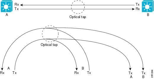
Another possible NAM installation enables you to monitor traffic between two devices by locating the Cisco Prime NAM 2300 series appliance between the two devices. Using traffic tapping, the network tap passes the traffic between the two devices while mirroring each direction of traffic to one of the NAM data ports.
You can connect the Cisco Prime NAM 2300 series appliance between two remote devices using an optical tap device. The optical tap mirrors the transmit sides of the cable that connects two remote devices as shown in Figure 2-4.
Note![]() The optical tap connection requires two additional fiber optical cables.
The optical tap connection requires two additional fiber optical cables.
Figure 2-4 Optical Tap Connection
Note![]() You can find optical tap and cable specifications in Appendix C, “Technical Specifications.”
You can find optical tap and cable specifications in Appendix C, “Technical Specifications.”
To use an optical tap to connect the Tx signals of two devices to the Cisco Prime NAM 2300 series appliance monitoring ports:
Step 1![]() Disconnect the 10 GE fiber optical cable that connects the two devices and plug the disconnected end of the cable into the appropriate ports on the optical tap for Device A.
Disconnect the 10 GE fiber optical cable that connects the two devices and plug the disconnected end of the cable into the appropriate ports on the optical tap for Device A.
Step 2![]() Plug another 10 GE fiber optical cable into the output port for Device B, then plug the other end into the appropriate ports on the topical tap for Device B.
Plug another 10 GE fiber optical cable into the output port for Device B, then plug the other end into the appropriate ports on the topical tap for Device B.
Step 3![]() Run a third 10 GE fiber optical cable from the Tx A/Tx B ports on the optical tap device to the Cisco Prime NAM 2300 series appliance.
Run a third 10 GE fiber optical cable from the Tx A/Tx B ports on the optical tap device to the Cisco Prime NAM 2300 series appliance.
Step 4![]() At the Cisco Prime NAM 2300 series appliance, separate the connectors at the end of the 10 GE fiber optical cable.
At the Cisco Prime NAM 2300 series appliance, separate the connectors at the end of the 10 GE fiber optical cable.
The two connectors of the 10 GE fiber optical cable plug into different SFPs enabling the appliance to monitor all traffic between the two devices. See Figure 2-5 for an illustration of the fiber optical cable inputs to the SFPs for an optical tap configuration.
Figure 2-5 Fiber Optical Cable Inputs for Optical Tap Configuration
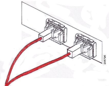
Step 5![]() Plug Device A’s Tx connector into the left side of the SFP on the right (logical DataPort1).
Plug Device A’s Tx connector into the left side of the SFP on the right (logical DataPort1).
Step 6![]() Plug the Device B Tx connector into the left side of the SFP on the left (logical DataPort2).
Plug the Device B Tx connector into the left side of the SFP on the left (logical DataPort2).
To use breakout mode configuration, use an optical tap to split the Tx and Rx signals of two connected devices so the NAM appliance receives the Tx of both devices to observe the transmitted output of each device.
There are two breakout mode configurations:
- Tx of one direction of the monitored data traffic is replicated on Tx of one breakout port and Tx of the other direction of the monitored data traffic is replicated on Tx of the other breakout port.
This case provides two output replicated ports: one for Tx in one direction and one for Tx of the other direction. Each replicated port is an input to a different monitoring port of the appliance to monitor both directions of traffic.
- Tx of one direction of the monitored data traffic is replicated in one Tx connection of the breakout port and Tx of the other direction of the monitored data traffic is replicated on the other Tx connection of the same breakout port.
This case provides only one replicated port which has Tx of both directions. This case requires you to split the connectors of one fiber optical cable and put one connector into one appliance monitoring port and put the other connector into a different appliance monitoring port.
Connect a Console Terminal
You can connect a console terminal using a PC running terminal-emulation software to the console port on the Cisco Prime NAM 2300 series appliance in either of two ways:
- Connect the terminal using a rollover cable to the appliance console port (see Figure 1-2 and Figure 1-4).
The rollover cable is provided in the cables shipped with your appliance.
After connecting the console terminal, observe the front-panel LEDs to verify that the connection is operating properly. (See “Reading the LEDs” section.)
Configure your terminal or terminal-emulation software as shown in Table 2-3 .
Connect a Monitor to the Appliance
You might want to connect a monitor to the Cisco Prime NAM 2300 series appliance, but it is not required; you can establish a console connection to the NAM appliance in other ways. The Cisco Prime NAM 2300 series appliance supports a VGA monitor.
The VGA monitor connector is located on the back panel of the appliance (see Figure 1-2 and Figure 1-4).
After connecting the monitor cable, observe the front-panel LEDs to verify that the connection is operating properly. (See “Reading the LEDs” section.)
Power Up the Appliance
After you have completed all connections for the Cisco Prime NAM 2300 series appliance, you can turn on AC power. The power switch is located on the front panel (see Figure 1-1 and Figure 1-3).
After the operating system boots up, observe the front-panel LEDs to verify that your system is operating properly. (See “Reading the LEDs” section.)
 Feedback