Maintaining the Cisco Prime NAM 2300 Series Appliances
This chapter provides instructions for maintaining your Cisco Prime NAM 2300 series appliance.
These instructions are intended for technicians who are experienced with installing, replacing, and removing the hardware components from electronic devices and are familiar with the Cisco Prime NAM 2300 series appliances. Additionally, site planners, network administrators, and facility maintenance personnel might also find this chapter helpful.
This chapter contains the following sections:
Reading the LEDs
There are several LEDs on a Cisco Prime NAM 2300 series appliance. LEDs serve the following purposes:
- Indicate that basic power is available to the appliance
- Guide you to a broken adapter card, or to one that has failed its diagnostics
- Give an indication that traffic is flowing through the adapter card to the appliance
The LEDs on the front panel of the Cisco Prime NAM 2300 series appliance and corresponding adapter card are aids for determining appliance and adapter performance and operation.
This section describes the location and meaning of LEDs and buttons and includes the following topics:
Cisco Prime NAM 2304 LEDs
These sections describe the location and meaning of the LEDs for the Cisco Prime NAM 2304 appliance:
Reading the Cisco Prime NAM 2304 Front-Panel LEDs
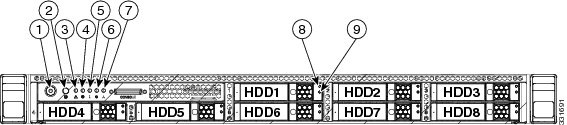
Figure 5-1 shows the front-panel LEDs for the Cisco Prime NAM 2304. Table 5-3 defines the LED states.
Figure 5-1 Cisco Prime NAM 2304 Front-Panel LEDs
1 |
Power button/Power status LED |
6 |
Power supply status LED |
2 |
Identification button/LED |
7 |
Network link activity LED |
3 |
System status LED |
8 |
Hard drive fault LED |
4 |
Fan status LED |
9 |
Hard drive activity LED |
5 |
Temperature status LED |
|
|
Table 5-1 Cisco Prime NAM 2304 Front-Panel LEDs
|
|
|
Power button/Power status LED |
- Off—There is no AC power to the appliance.
- Amber—The appliance is in standby power mode. Power is supplied only to the CIMC and some motherboard functions.
- Green—The appliance is in main power mode. Power is supplied to all appliance components.
|
Identification |
- Off—The Identification LED is not in use.
- Blue—The Identification LED is activated.
|
NAM status |
- Green—The appliance is running in normal operating condition.
- Green, blinking—The appliance is performing system initialization and memory check.
- Amber, steady—The appliance is in a degraded operational state. For example:
– Power supply redundancy is lost. Power supply redundancy is lost. – CPUs are mismatched. – At least one CPU is faulty. – At least one DIMM is faulty. – At least one drive in a RAID configuration failed.
- Amber, blinking—The appliance is in a critical fault state. For example:
– Boot failed. – Fatal CPU and/or bus error is detected. – The appliance is in over-temperature condition. |
Fan status |
- Green—All fan modules are operating properly.
- Amber, steady—One fan module has failed.
- Amber, blinking—Critical fault, two or more fan modules have failed.
|
Temperature status |
- Green—The appliance is operating at normal temperature.
- Amber, steady—One or more temperature sensors have exceeded a warning threshold.
- Amber, blinking—One or more temperature sensors have exceeded a critical threshold.
|
Power supply status |
- Green—All power supplies are operating normally.
- Amber, steady—One or more power supplies are in a degraded operational state.
- Amber, blinking—One or more power supplies are in a critical fault state.
|
Network link activity |
- Off—The Ethernet link is idle.
- Green—One or more Ethernet LOM ports are link-active, but there is no activity.
- Green, blinking—One or more Ethernet LOM ports are link-active, with activity.
|
Hard drive fault |
- Off—The hard drive is operating properly.
- Amber—This hard drive has failed.
- Amber, blinking—The device is rebuilding.
|
Hard drive activity |
- Off—There is no hard drive in the hard drive sled (no access, no fault).
- Green—The hard drive is ready.
- Green, blinking—The hard drive is reading or writing data.
|
Reading the Cisco Prime NAM 2304 Rear-Panel LEDs
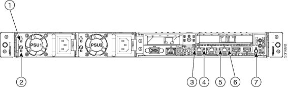
Figure 5-2 shows the rear-panel LEDs for the Cisco Prime NAM 2304. Table 5-2 defines the LED states.
Figure 5-2 Cisco Prime NAM 2304 Rear-Panel LEDs
1 |
Power supply fault LED |
5 |
1-Gb Ethernet link speed LED |
2 |
Power supply AC OK LED |
6 |
1-Gb Ethernet link status LED |
3 |
1-Gb Ethernet dedicated management link status LED |
7 |
Rear Identification button/LED |
4 |
1-Gb Ethernet dedicated management link speed LED |
|
|
Table 5-2 Cisco Prime NAM 2304 Rear-Panel LEDs
|
|
|
Power supply fault |
- Off—The power supply is operating normally.
- Amber, blinking—An event warning threshold has been reached, but the power supply continues to operate.
- Amber, solid—A critical fault threshold has been reached, causing the power supply to shut down (for example, a fan failure or an over-temperature condition).
|
Power supply AC OK |
- Off—There is no AC power to the power supply.
- Green, blinking—AC power OK, DC output not enabled.
- Green, solid—AC power OK, DC outputs OK.
|
1-Gb Ethernet dedicated management link speed |
- Off—link speed is 10 Mbps.
- Amber—link speed is 100 Mbps.
- Green—link speed is 1 Gbps.
|
1-Gb Ethernet dedicated management link status |
- Off—No link is present.
- Green—Link is active.
- Green, blinking—Traffic is present on the active link.
|
1-Gb Ethernet link speed |
- Off—Link speed is 10 Mbps.
- Amber—Link speed is 100 Mbps.
- Green—Link speed is 1 Gbps.
|
1-Gb Ethernet link status |
- Off—No link is present.
- Green—Link is active.
- Green, blinking—Traffic is present on the active link.
|
Identification |
- Off—The Identification LED is not in use.
- Blue—The Identification LED is activated.
|
Cisco Prime NAM 2320 LEDs
These sections describe the location and meaning of the LEDs for the Cisco Prime NAM 2320 appliance:
Reading the Cisco Prime NAM 2320 Front-Panel LEDs
Figure 5-3 shows the front-panel LEDs for the Cisco Prime NAM 2320. Table 5-3 defines the LED states.
Figure 5-3 Cisco Prime NAM 2320 Front-Panel LEDs
1 |
Hard drive fault LED |
6 |
Fan status LED |
2 |
Hard drive activity LED |
7 |
System status LED |
3 |
Network link activity LED |
8 |
Identification button/LED |
4 |
Power supply status LED |
9 |
Power button/power status LED |
5 |
Temperature status LED |
|
|
Table 5-3 Cisco Prime NAM 2320 Front-Panel LEDs
|
|
|
Hard drive fault |
- Off—The hard drive is operating properly.
- Amber—This hard drive has failed.
- Amber, blinking—The device is rebuilding.
|
Hard drive activity |
- Off—There is no hard drive in the hard drive sled (no access, no fault).
- Green—The hard drive is ready.
- Green, blinking—The hard drive is reading or writing data.
|
Network link activity |
- Off—The Ethernet link is idle.
- Green—One or more Ethernet LOM ports are link-active, but there is no activity.
- Green, blinking—One or more Ethernet LOM ports are link-active, with activity.
|
Power supply status |
- Green—All power supplies are operating normally.
- Amber, steady—One or more power supplies are in a degraded operational state.
- Amber, blinking—One or more power supplies are in a critical fault state.
|
Temperature status |
- Green—The appliance is operating at normal temperature.
- Amber, steady—One or more temperature sensors have exceeded a warning
- threshold.
- Amber, blinking—One or more temperature sensors have exceeded a critical threshold.
|
Fan status |
- Green—The appliance is operating at normal temperature.
- Amber, steady—One or more temperature sensors have exceeded a warning
- threshold.
- Amber, blinking—One or more temperature sensors have exceeded a critical threshold.
|
NAM status |
- Green—The appliance is running in normal operating condition.
- Green, blinking—The appliance is performing system initialization and memory check.
- Amber, steady—The appliance is in a degraded operational state. For example:
– Power supply redundancy is lost. – CPUs are mismatched. – At least one CPU is faulty. – At least one DIMM is faulty. – At least one drive in a RAID configuration failed.
- Amber, blinking—The appliance is in a critical fault state. For example:
– Boot failed. – Fatal CPU and/or bus error is detected. – The appliance is in over-temperature condition. |
Identification |
- Off—The Identification LED is not in use.
- Blue—The Identification LED is activated.
|
Power button/Power status LED |
- Off—There is no AC power to the appliance.
- Amber—The appliance is in standby power mode. Power is supplied only to the CIMC and some motherboard functions.
- Green—The appliance is in main power mode. Power is supplied to all appliance components.
|
Reading the Cisco Prime NAM 2320 Rear-Panel LEDs
Figure 5-4 shows the front-panel LEDs for the Cisco Prime NAM 2320. Table 5-4 defines the LED states.
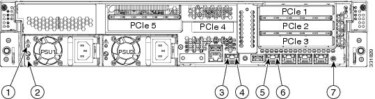
Figure 5-4 Cisco Prime NAM 2320 Rear-Panel LEDs
1 |
Power supply fault LED |
5 |
1-Gb Ethernet link speed LED |
2 |
Power supply AC OK LED |
6 |
1-Gb Ethernet link status LED |
3 |
1-Gb Ethernet dedicated management link status LED |
7 |
Identification button/LED |
4 |
1-Gb Ethernet dedicated management link speed LED |
|
|
Table 5-4 Cisco Prime NAM 2320 Rear-Panel LEDs
|
|
|
Power supply fault |
- Off—The power supply is operating normally.
- Amber, blinking—An event warning threshold has been reached, but the power supply continues to operate.
- Amber, solid—A critical fault threshold has been reached, causing the power supply to shut down (for example, a fan failure or an over-temperature condition).
|
Power supply AC OK |
- Off—There is no AC power to the power supply.
- Green, blinking—AC power OK, DC output not enabled.
- Green, solid—AC power OK, DC outputs OK.
|
1-Gb Ethernet dedicated management link speed |
- Off—link speed is 10 Mbps.
- Amber—link speed is 100 Mbps.
- Green—link speed is 1 Gbps.
|
1-Gb Ethernet dedicated management link status |
- Off—No link is present.
- Green—Link is active.
- Green, blinking—Traffic is present on the active link.
|
1-Gb Ethernet link speed |
- Off—link speed is 10 Mbps.
- Amber—link speed is 100 Mbps.
- Green—link speed is 1 Gbps.
|
1-Gb Ethernet link status |
- Off—No link is present.
- Green—Link is active.
- Green, blinking—Traffic is present on the active link.
|
Identification |
- Off—The Identification LED is not in use.
- Blue—The Identification LED is activated.
|
Reading the NIC LEDs
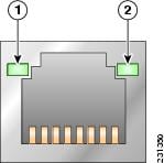
Figure 5-5 shows the NIC 1 LEDs located on the rear of the NAM appliance. These LEDs indicate the connection activity and speed of the NIC ports. Table 5-5 describes the activity and connection speed associated with each LED state.
Figure 5-5 NIC 1 LEDs
Table 5-5 NIC 1 LED Descriptions
|
|
|
|
|
|
| 1 |
Left |
|
Off |
No network connection |
Green |
Solid |
Network connection |
Green |
Blinking |
Transmit/receive activity |
| 2 |
Right |
|
Off |
10-Mb/s connection (if left LED is on or blinking) |
Green |
Solid |
100-Mb/s connection |
Amber |
Solid |
1000-Mb/s (or 1-Gb/s) connection |
Reading the AC Power Supply LED
The rear of Cisco Prime NAM 2300 series appliances include LEDs that indicate the power status of the AC power supply. (See location 2 in Figure 5-2 and Figure 5-4.) Table 5-6 describes the power status associated with the AC power supply LED.
Table 5-6 AC Power Supply LED
|
|
|
|
|
| Below AC power supply input connector |
|
Off |
No AC input power to power supply |
Green |
Blinking |
AC power applied to power supply and standby voltages are available |
Green |
Solid |
All power available |
Amber |
Blinking |
AC power supply warning due to overcurrent or overtemperature condition or slow fan |
Amber |
Solid |
AC power supply failed or shut down due to blown fuse, high overcurrent or overtemperature condition, or fan failure |
Replacing Appliance Components
Table 5-7 lists the Field Replaceable Units (FRUs) of the Cisco Prime NAM 2300 series appliances.
Replacing Transceiver Modules
To replace an SFP or an SFP+ transceiver module in a Cisco Prime NAM 2300 series appliance:
Step 1 Locate the new transceiver module you plan to install, remove any protective packaging, and examine it for any signs of damage.
Step 2 Determine which module you want to replace on the Cisco Prime NAM rear panel.
Step 3 Remove the fiber optical cable from the module to be replaced.
Step 4 With your finger, pull the latch down to release the module from its latched position (see Figure 2-2).
Step 5 Using the latch, pull the SFP+ out of the appliance and place it in a safe location.
Step 6 Insert the new SFP+ into the slot and slide it in until you feel resistance, then push the SFP+ harder until you feel (or hear) it click into its socket.
Step 7 With your finger, pull the latch upwards to lock the SFP+ into its slot (see Figure 2-3).
Step 8 Replace the fiber optical cable.
Removing and Replacing a Hard Disk Drive
For information about replacing hard disk drives in Cisco Prime NAM 2300 series appliances, see the following UCS installation guides:
Installing or Replacing a Power Supply
For information about replacing power supplies in Cisco Prime NAM 2300 series appliances, see the following UCS installation guides:
Removing or Replacing the Cisco Prime NAM 2300 Series Appliances
Always use the NAM CLI command shutdown to shut down the NAM application when you turn power off.
Warning Power off the unit before you begin. Statement 237
Warning Ultimate disposal of this product should be handled according to all national laws and regulations. Statement 1040
To remove a Cisco Prime NAM 2300 series appliance from your network, power it down, disconnect the power cords and network cables, and physically remove the appliance from the rack.
The appliance is in constant communication on your network, which means that when the network notices that the appliance is no longer responding to it, the network stops sending requests to the appliance. This change is transparent to users. If other appliances are attached to the network, the network continues sending requests to the other appliances.
To replace an appliance, remove it from the network. Then, install a new appliance and configure it using the same configuration parameters that you used for the removed appliance.


 Feedback