Power and Cooling
This chapter describes the Cisco CRS Carrier Routing System 8-Slot Line Card Chassis Enhanced router power and cooling systems. It also provides the power, grounding, and cooling requirements for the installation site to help you plan the site facilities for the system. The Cisco CRS Carrier Routing System 8-Slot Line Card Chassis Enhanced Router System Description provides detailed information about these components.
This chapter contains the following sections:
- Chassis Power System
- General Power and Grounding Requirements
- Bonding and Grounding Guidelines
- DC Power System
- AC Power Systems
- Chassis Airflow
- Facility Cooling Requirements
Chassis Power System
The chassis power system provides power to chassis components and is made up of two power shelves that contain power modules. Each power shelf is connected to a separate and independent power source. Input power enters the power shelves and is processed by the power modules before being distributed to the components in the chassis. At the shelf level, the power system provides 2N redundancy; the PMs themselves provide load-share redundancy.
The Cisco CRS 8-Slot Line Card Chassis Enhanced router can be either DC or AC powered. The AC power system requires single-phase AC input power to power the shelves. If you have 3-phase AC-Delta or AC-Wye at your equipment, a Cisco CRS 3-Phase AC PDU will be required to convert 3-phase AC input power to single-phase AC input power for the power shelf.
 Note | In an AC power system, PDU refers to the Cisco CRS 3-phase AC PDU which is required to convert 3-phase AC-Wye or AC-Delta input power to single-phase AC input power for the AC power shelf. For further information, refer to Cisco CRS 3-Phase AC Power Distribution Unit Installation Guide . |
Maximum input power requirements for the Cisco CRS 8-Slot Line Card Chassis Enhanced router are as follows:
- DC-powered chassis requires up to a maximum of 9,500 watts (9.5 kW) of DC input power when the chassis is fully loaded.
- AC-powered chassis requires up to a maximum of 9,800 watts (9.8 kW) of AC input power when the chassis is fully loaded.
Note | If you have a Cisco CRS 3-phase AC PDU installed, three AC PMs are required to be installed in each AC power shelf to maintain a balanced 3-phase power load. |
Note | These power requirements are for a fully loaded chassis with eight PLIMs. A chassis with six or seven PLIMs uses slightly less power. However, it is a good idea to allocate this much power for each chassis to ensure that enough power is available for future system expansion. |
See the Cisco CRS Carrier Routing System 8-Slot Line Card Chassis Enhanced Router System Description for detailed information about how each power system operates and distributes power to components in the chassis.
General Power and Grounding Requirements
This section describes the power and grounding requirements you must consider when planning the site facilities for the routing system. In addition, see the DC Power System section or the AC Power Systems section for additional information about the power requirements for your chassis type.
Note | A qualified electrician should review the information in these sections to ensure that the installation site meets these requirements. For larger system configurations, consult a facilities electrical expert to understand the load that the routing system may put on the facility power plant. |
General power and grounding requirements are:
- Installation of the routing system must follow national and local electrical codes:
- Two separate and independent AC or DC power sources are needed to provide 2N redundancy for system power. Each power source requires its own circuit breaker.
- Each power source must provide clean power to the site. If necessary, install a power conditioner.
- The site must provide short-circuit (over-current) protection for devices.
- Proper grounding
is required at the site to ensure that equipment is not damaged by lightning
and power surges. In addition:
- Chassis grounding is required for AC and DC-powered systems.
- For AC-powered systems, a grounding-type AC power outlet is required.
- Site power planning must include the power requirements for any external terminals and test equipment you will use with your system.
Note | Be sure to review the safety warnings in Regulatory Compliance and Safety Information for the Cisco CRS Carrier Routing System before attempting to install the routing system. |
Bonding and Grounding Guidelines
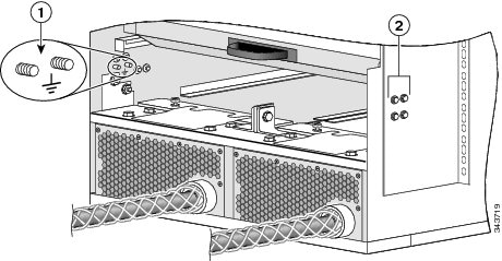
The chassis allows you to connect the central office ground system or interior equipment ground system to the bonding and grounding receptacles on the router chassis. Six chassis grounding points are provided at the rear (MSC) side of the chassis, as shown in the following figure. Each side of the chassis has one pair of threaded ground studs located on the inside of the chassis and two pairs of grounding receptacles located on the outside of the chassis. These ground points are also called the network equipment building system (NEBS) bonding and grounding points.
Note | These bonding and grounding receptacles satisfy the Telcordia NEBS requirements for bonding and grounding connections. |
|
1 |
NEBS bonding and grounding points (inside chassis) |
|
2 |
NEBS bonding and grounding points (outside chassis) |
To connect the chassis to a NEBS-compliant bonding and grounding system at your site, you must have the following:
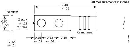
- One straight (180 degree) grounding lug that has two M6 bolt holes with 0.63 inches (1.60 cm) of spacing center to center between them and a 6-AWG or larger multistrand copper wire. See the following figure.
- Four M6 hex-head nuts with integrated locking washers are shipped pre-installed on the inside of the chassis.
- Eight M6 hex-head bolts with integrated locking washers are shipped pre-installed on the outside of the chassis.
- Cisco recommends at least 6 AWG multistrand copper cable. This cable is not available from Cisco Systems; it is available from any commercial cable vendor. The cable should be sized according to local and national installation requirements.
 Caution | The DC Return of the Cisco CRS 8-Slot Line Card Chassis Enhanced router should remain isolated from the system frame and chassis (DC-I: Isolated DC Return). |
For additional information about NEBS, see Cisco CRS Carrier Routing System Regulatory Compliance and Safety Information .
DC Power System
Each DC powered chassis contains two power shelves for 2N redundancy. The power shelves contain the input power connectors. Each shelf can contain up to four DC PMs. The power shelves and DC PMs are field replaceable.
DC Power Requirements
Observe the following guidelines for DC-powered shelves. In addition, be sure to review the requirements described in the Bonding and Grounding Guidelines section.
- A DC-powered chassis requires up to a maximum of 9,500 watts of DC input power when the chassis is fully loaded.
- Two separate and independent power sources are required for N+N redundancy, each providing nominal –48/-60 VDC, 60 A service (four inputs per shelf). The system will operate with power to only one shelf but will not have N+N redundancy.
- All power connection wiring must conform to the rules and regulations in the National Electrical Code (NEC) and any local codes. In addition, make sure that the wiring conforms to any internal requirements at the installation site.
- Each DC power source must comply with the safety extra-low voltage (SELV) requirements in UL 60950-1, CSA-C22.2 No. 60950-1, EN60950-1, AS/NZS 60950, and IEC60950-1.
- A DC-powered system should be installed in a restricted access area in accordance with the National Electric Code, ANSI/NFPA 70.
- All components in the area where DC input power is accessible must be properly insulated.
- If it is not possible to rely on the identification of the earthed conductor in the DC mains supply, whereby the equipment is not provided with a two-pole disconnect device, then a two-pole disconnect device is to be provided external to the equipment.
The following table lists the DC input current and voltage specifications.
|
Nominal input voltage |
–48 VDC North America–60 VDC European Community(range: –40 VDC to –72 VDC) |
|
Input line current |
50 A maximum at –48 VDC40 A maximum at –60 VDC60 A maximum at -40 VDC |
DC Power Shelf Wiring
Each power shelf contains four pairs of double-stud terminals (RTN, –48V/–60V) for connecting DC input power. To provide 2N power redundancy, one power shelf should be connected to the central office “A” power bus and the other power shelf should be connected to the “B” power bus.
The requirements for the DC input power connections are as follows:
- Each power shelf requires up to four pairs of distribution cables, DC (–48) and RTN (+).
- Paired battery and RTN cables should have the same cable lengths and should run together for equalization.
- Use the appropriate wire gauge for –48/-60 VDC, 60 A service. We recommend that you use a commensurately rated, high-strand-count copper cable. This cable is not available from Cisco Systems; it is available from any commercial vendor.
Caution | A certified electrician must select the appropriate DC input power cable based on standard electrical practices, such as derating factors, wiring type, operating temperatures, and so on. The electrician must verify that the cable complies with the National Electrical Code (NEC) and local codes and any guidelines in effect at the installation site. At minimum, DC input power cables must be 6-AWG or heavier and rated for 90°C (194°F) temperature or higher. |
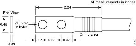
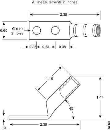
- Each DC input power cable is terminated at the power shelf by a cable lug. The power supply terminal block lug opening width is 0.63 inch (1.60 cm). The cable lug must be dual hole and able to fit over M6 terminal studs at 0.63-inch (1.60 cm) centers. We recommend that you use an appropriately sized 180-degree angle (straight) industry standard dual-hole, standard barrel compression lug, as shown in 180 Degree (Straight) DC Input Power Cable Lug, or an appropriately sized 45-degree angle industry standard 2-hole, standard barrel compression lug, as shown in 45 Degree DC Input Power Cable Lug.
Note | Use local electrical codes for clearance requirements when using power lugs to ensure safe operation. |
The following figure shows the DC input power cables connected to the DC power shelf terminal studs.
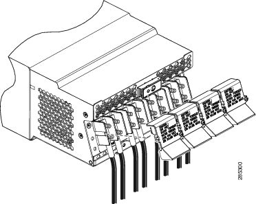
Note | In the DC power system, the power wire connectors have a torque value of 20 in-lb (2.26 N-m). |
AC Power Systems
The chassis power system provides the necessary power for chassis components. Site power requirements differ, depending on the input source voltage available, i.e. single-phase AC, AC Delta or AC Wye.
Each AC powered chassis contains two AC power shelves for 2N redundancy. The power shelves contain the input power connectors. Each AC power shelf can contain up to three AC PMs. The power shelves and AC PMs are field replaceable.
AC Power Requirements
In addition to the requirements in the Bonding and Grounding Guidelines section, AC input power requirements are as follows:
- An AC-powered chassis requires up to a maximum of 9,800 watts of AC input power when the chassis is fully loaded.
- Two separate and independent AC power sources are required for N+N redundancy, one for each power shelf. Each power shelf should be connected to a different power source to provide 2N power redundancy in case a power source fails. The system will operate with power to only one shelf but will not have N+N redundancy.
- Each AC power source must provide single-phase AC power, and have its own circuit breaker.
- The AC power receptacles used to plug in the chassis must be the grounding type. The grounding conductors that connect to the receptacles should connect to protective earth ground at the service equipment.
- AC single-phase
input:
- Single-phase, 200 to 240 VAC nominal, 50 to 60 Hz, 16 A International and 20 A North America.
- Each AC power shelf contains three IEC-320-C22 receptacles which can accept up to three IEC-320-C21 connector female plugs.
- If you have 3-phase AC Delta or AC Wye at your equipment, a Cisco CRS 3-phase AC PDU will be required to convert 3-phase AC input power to single-phase AC input power for the power shelf. For further information, refer to Cisco CRS 3-Phase AC Power Distribution Unit Installation Guide .
Note | If you have a Cisco CRS 3-phase AC PDU installed, three AC PMs are required to be installed in each AC power shelf to maintain a balanced 3-phase power load. |
For detailed AC power specifications, see the Line Card Chassis Specifications section.
AC Power Shelf Wiring
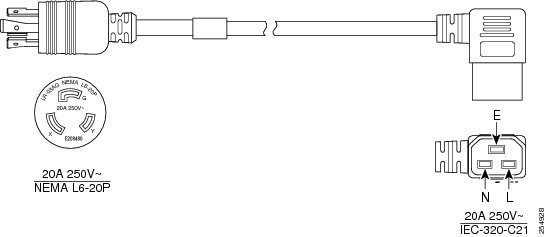
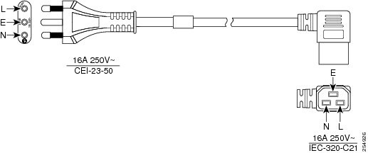
The AC power shelf is shipped with AC power cords when the AC PDU is not ordered. Each AC power shelf accepts up to three power cords. Each AC power cord is 4.25 m in length and different plug types (pre-attached) are available, depending on the locale. AC power cords are available for the following locales:
The following table lists the single-phase AC-input cord power options and Cisco product numbers for the Cisco CRS 8-Slot Line Card Chassis Enhanced router with AC power shelves installed. The table also references power cord illustrations.
|
Locale |
Cisco Product Number |
Plug Rating |
Reference Illustration |
|---|---|---|---|
|
North America |
CRS-AC-CAB-NA(=) |
20 A/250 VAC |
|
|
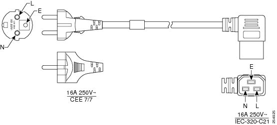
Europe |
CRS-AC-CAB-EU(=) |
16 A/250 VAC |
|
|
United Kingdom |
CRS-AC-CAB-UK(=) |
13 A/250 VAC |
|
|
Italy |
CRS-AC-CAB-IT(=) |
16 A/250 VAC |
|
|
Australia |
CRS-AC-CAB-AU(=) |
15 A/250 VAC |
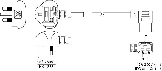
Note | The BS-1363 standard rates cord sets up to a maximum of 13 A, 250 VAC for the C-21 plug. Therefore, the building circuit breaker must be 13 A maximum. Installation of the Cisco CRS 8-slot line card chassis must follow national and local electrical codes. |
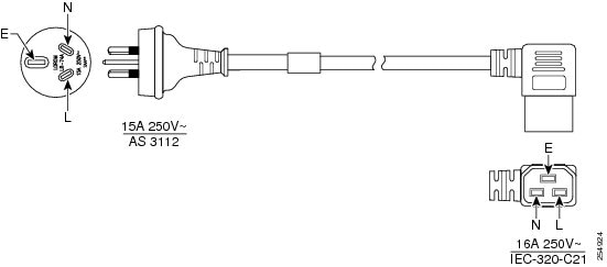
Note | The AS 3112 standard rates cord sets up to a maximum of 15 A, 250 VAC for the C-21 plug. Therefore the building circuit breaker must be 15 A maximum. Installation of the Cisco CRS 8-slot line card chassis must follow national and local electrical codes. |
Converting 3-Phase AC to Single-Phase AC
If you have 3-phase AC Delta or AC Wye input power at your equipment, a Cisco CRS 3-phase AC PDU will be required to convert 3-phase AC Delta or AC Wye input power to single-phase AC input power that connects directly to the rear of the AC power shelf. The Cisco CRS PDU includes either an AC Delta or AC Wye power interface, and has power input and power output cords entering and exiting the box.
There are two versions of the Cisco CRS 3-Phase AC PDU available for the Cisco CRS8-Slot Line Card Chassis Enhanced router:
- CRS-8-PDU-Delta—Redundant 3-phase to single-phase Delta PDU for Cisco CRS 8-Slot Line Card Chassis Enhanced router, 2 input/6 output
- CRS-8-PDU-Wye—Redundant 3-phase to single-phase Wye PDU for Cisco CRS 8-Slot Line Card Chassis Enhanced router, 2 input/6 output
In addition to the requirements in the General Power and Grounding Requirements section, AC input power requirements are as follows:
- Two separate and independent AC power sources are required, one for each PDU. Each PDU should be connected to a different power source to provide 2N power redundancy in case a power source fails.
- Each AC power source must provide 3-phase VAC power, and have its own circuit breaker.
- AC Delta input:
- 3-phase, 200 to 240 VAC (phase-to-phase), 50 to 60 Hz.
- Input current: 27.7 A.
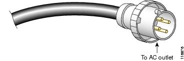
- Each PDU has one Delta input power cord with a 4-pin IEC 60309 plug (3 wire + protective earthing [3W+PE]). The power cord is rated for 250 VAC, 60 A, and plugs into a similarly rated IEC 60309 receptacle.
- Each PDU has three single phase output cords preattached, each with a 90 degree IEC-320-C21 plug that plugs into a IEC-320-C22 inlet on the rear of the AC power shelf.
- AC Wye input:
- 3-phase, 200 to 240 VAC (phase-to-neutral), 50 to 60 Hz.
- Input current: 16 A (International) or 20 A (North America). The PDU is rated for 16-amp service.
- Each PDU has one Wye power cord with a 5-pin IEC 60309 plug (3 wire + neutral + protective earthing conductor (ground wire) [3W+N+PE]). The cord is rated for 415 VAC, 16 A, and plugs into a similarly rated IEC 60309 receptacle.
- Grounding-type AC power outlet is required. The PDUs are shipped with AC power cords that have a grounding-type plug. As a safety feature, the plugs fit only a grounding-type AC power outlet.

For detailed Cisco CRS Power Distribution Unit AC power specifications, see the Cisco CRS 3-Phase AC Power Distribution Unit Installation Guide.
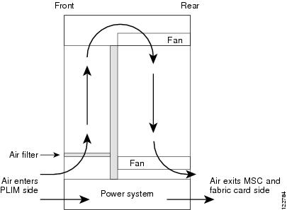
Chassis Airflow
The Cisco CRS 8-Slot Line Card Chassis Enhanced router has two fan trays, with four fans each, that cool the chassis card cages. Cool air flows in at the bottom front of the chassis and flows through the chassis card cages and through the fans in the fan trays before being exhausted through the bottom rear of the chassis, as shown in the following figure.
A replaceable air filter is located on the front of the chassis below the PLIM card cage. How often you should replace the air filters depends on the facility environment.
In a dirty environment, or when you start getting frequent temperature alarms, you should always check the intake grills for debris, and then check the air filters to see if they need to be replaced.
Note | We recommend that you check the air filters once a month. Replace a filter when you notice a significant amount of dust. |
The Cisco CRS 8-Slot Line Card Chassis Enhanced router airflow volumes are as follows:
Facility Cooling Requirements
The Cisco CRS 8-Slot Line Card Chassis Enhanced router dissipates considerable power that generates much heat. In large configurations, additional air cooling is required to maintain correct operating temperatures. The room air must be cooled by external cooling units that are installed as part of the routing system.
Heat dissipation and external cooling requirements for the Cisco CRS 8-Slot Line Card Chassis Enhanced router are as follows:
To ensure that the site provides the proper air circulation for the system:
- Make certain that the site is as dust free as possible. Dusty environments can clog the air filter or power supply intake vents, reducing the cooling airflow through the system.
- Allow sufficient airflow by maintaining a minimum of 6 inches (15.2 cm) of clearance at both the inlet and exhaust openings on the chassis. If airflow is blocked or restricted, or if inlet air is too warm, an over-temperature condition can occur. Under extreme conditions, the environmental monitoring system shuts down the power to protect the routing system components.
 Feedback