- SPA Summary
- Bandwidth Oversubscription
- 1-Port and 3-Port Clear Channel OC-3 ATM SPA Overview
- 1-Port Clear Channel OC-12 ATM SPA Overview
- 4-Port and 8-Port OC-3c/STM-1 POS SPA Overview
Overview: Cisco
CRS-1 Shared Port Adapters
This chapter describes the shared port adapters (SPAs) that are supported on the Cisco CRS-1 SIP-800 and the Cisco CRS-3 Flexible PLIM.
This chapter contains the following sections:
- SPA Summary
- Bandwidth Oversubscription
- 1-Port and 3-Port Clear Channel OC-3 ATM SPA Overview
- 1-Port Clear Channel OC-12 ATM SPA Overview
- 4-Port and 8-Port OC-3c/STM-1 POS SPA Overview
- 4-Port and 8-Port OC-12c/STM-4 Multirate POS SPA Overview
- 2-Port and 4-Port OC-48c/STM-16 POS/RPR SPA Overview
- 1-Port OC-192c/STM-64 POS/RPR XFP SPA Overview
- 1-Port OC-192c/STM-64 POS/RPR VSR Optics SPA Overview
- 5-Port Gigabit Ethernet SPA Overview
- 8-Port Gigabit Ethernet SPA Overview
- 10-Port Gigabit Ethernet SPA Overview
- 1-Port 10-Gigabit Ethernet SPA Overview
- 2-Port and 4-Port Clear Channel T3/E3 SPA Overview
SPA Summary
Refer the below tables for summary descriptions of SPAs supported on the Cisco CRS-1 SIP-800 and SPAs supported on the Cisco CRS-3 Flexible PLIM.
|
SPA |
SPA Part Number |
Number of Ports |
Minimum Cisco IOS XR Software |
Minimum Hardware Revision |
|---|---|---|---|---|
|
1-Port Clear Channel OC-3 ATM SPA |
SPA-1XOC3-ATM-V2 |
1 |
Release 3.8.0 |
1.0 |
|
3-Port Clear Channel OC-3 ATM SPA |
SPA-3XOC3-ATM-V2 |
3 |
Release 3.7.0 |
1.0 |
|
1-Port Clear Channel OC-12 ATM SPA |
SPA-1XOC12-ATM-V2 |
1 |
Release 3.7.0 |
1.0 |
|
4-Port OC-3c/STM-1 POS SPA |
SPA-4XOC3-POS |
4 |
Release 3.2 |
1.0 |
|
8-Port OC-12c/STM-4 Multirate POS SPA |
SPA-8XOC12-POS |
8 |
Release 3.3.0 |
1.0 |
|
2-Port OC-48c/STM-16 POS/RPR SPA |
SPA-2XOC48POS/RPR |
2 |
Release 3.4.0 |
1.0 |
|
4-Port OC-48c/STM-16 POS/RPR SPA |
SPA-4XOC48POS/RPR SPA-4XOC3-POS-V2 |
4 |
Release 3.4.0 Release 3.4.0 |
1.0 |
|
1-Port OC-192c/STM-64 POS/RPR XFP SPA |
SPA-OC192POS-XFP |
1 |
Release 3.2 |
1.0 |
|
1-Port OC-192c/STM-64 POS/RPR VSR Optics SPA |
SPA-OC192POS-VSR |
1 |
Release 3.4.1 |
1.0 |
|
5-Port Gigabit Ethernet SPA |
SPA-5X1GE-V2 |
5 |
Release 3.4.0 |
1.0 |
|
8-Port Gigabit Ethernet SPA |
SPA-8X1GE SPA-8X1GE-V2 |
8 |
Release 3.2 Release 3.4.0 |
1.0 |
|
10-Port Gigabit Ethernet SPA |
SPA-10X1GE-V2 |
10 |
Release 3.4.0 |
1.0 |
|
1-Port 10-Gigabit Ethernet SPA |
SPA-1X10GE-L-V2 SPA-1X10GE-WL-V2 |
1 |
Release 3.4.0 Release 3.5.0 |
1.0 |
|
2-Port Clear Channel T3/E3 SPA |
SPA-2XT3/E3 |
2 |
Release 3.4.1 |
1.0 |
|
4-Port Clear Channel T3/E3 SPA |
SPA-4XT3/E3 |
4 |
Release 3.4.1 |
1.0 |
|
SPA |
SPA Part Number |
Number of Ports |
Minimum Cisco IOS XR Software |
Minimum Hardware Revision |
|---|---|---|---|---|
|
1-Port OC-192c/STM-64 POS/RPR XFP SPA |
SPA-OC192POS-XFP |
1 |
Release 4.3.0 |
1.0 |
|
2-Port OC-48c/STM-16 POS SPA |
SPA-2XOC48-POS |
2 |
Release 4.3.2 |
1.0 |
|
4-Port OC-3c/STM-1 POS SPA |
SPA-4XOC3-POS-V2 |
4 |
Release 4.3.2 |
1.0 |
|
4-Port OC-48c/STM-16 POS/RPR SPA |
SPA-4XOC48POS/RPR |
4 |
Release 4.3.0 |
1.0 |
|
1-Port 10-Gigabit Ethernet SPA |
SPA-1X10GE-L-V2 SPA-1X10GE-WL-V2 |
1 |
Release 4.3.2 Release 4.3.2 |
1.0 |
|
8-Port Gigabit Ethernet SPA |
SPA-8X1GE-V2 |
8 |
Release 4.3.0 |
1.0 |
|
10-Port Gigabit Ethernet SPA |
SPA-10X1GE-V2 |
10 |
Release 4.3.2 |
1.0 |
|
4-Port OC-3c/STM-1 POS SPA |
SPA-4XOC3-POS |
4 |
Release 4.3.1 |
1.0 |
|
4-Port OC-12c/STM-4 Multirate POS SPA |
SPA-4XOC12-POS |
4 |
Release 4.3.1 |
1.0 |
|
8-Port OC-12c/STM-4 Multirate POS SPA |
SPA-8XOC12-POS |
8 |
Release 4.3.1 |
1.0 |
|
8-Port OC-3c/STM-1 POS SPA |
SPA-8XOC3-POS |
8 |
Release 4.3.1 |
1.0 |
Bandwidth Oversubscription
Oversubscribing the bandwidth limit recommendations of a router can result in decreased or degraded performance. For this reason, it is important to determine the amount of bandwidth used by the SPAs on the router and verify that the total bandwidth used by all SPAs does not exceed the recommended bandwidth limit of the router. It is also important not to exceed the bandwidth of the SIP. For information on SIP bandwidth, see the SIP Summary.
Cisco CRS-1 SIP-800
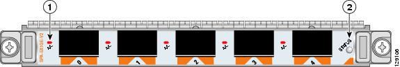
The processing on the Cisco CRS-1 SIP-800 is performed by two PLIM ASICs, each of which can process up to 20 Gbps of traffic. SPA subslots 0, 1, and 3 are associated with one PLIM ASIC, while SPA subslots 2, 4, and 5 are associated with the second PLIM ASIC. See the figure below for subslot locations.
|
1 |
Subslots controlled by one PLIM ASIC |
2 |
Subslots controlled by second PLIM ASIC |
If you are using only Gigabit Ethernet SPAs on the Cisco CRS-1 SIP-800, then the SIP can be oversubscribed. The Cisco CRS-1 SIP-800 can pass a maximum of 40 Gbps of traffic, so if you have six 8-Port Gigabit Ethernet SPAs operating at almost full capacity, the SIP is oversubscribed.
If you are using any Packet Over Sonet (POS) SPAs in the Cisco CRS-1 SIP-800, regardless of the bandwidth of the SPA interfaces (OC-3c/STM-1, OC-12c/STM-4, OC-48c/STM-16, or OC-192c/STM-64), no oversubscription of either PLIM ASIC is allowed, nor can the total bandwidth of the SIP exceed 40 Gbps. For this reason, you can install a maximum of four OC-192c/STM-64 POS SPAs in the Cisco CRS-1 SIP-800. Two of them must be installed in subslots 0, 1, or 3; the other two must be installed in subslots 2, 4, or 5. The following arrangement of SPAs within the SIP indicates a valid configuration that optimizes the use of the available PLIM ASIC bandwidth:
|
Subslot 0: OC-192c/STM-64 POS SPA |
Subslot 1: OC-192c/STM-64 POS SPA |
Subslot 2: 8-Port Gigabit Ethernet SPA |
|
Subslot 3: Empty |
Subslot 4: 8-Port Gigabit Ethernet SPA |
Subslot 5: 4-Port OC-3c/STM-1 POS SPA |
In this example, because at least one OC-192c/STM-64 POS SPA is installed, the maximum bandwidth allowed on the first PLIM ASIC (associated with subslots 0, 1, and 3) is 20 Gbps, and the total capacity of the SIP is controlled to be 40 Gbps or less. The total bandwidth usage required in this example is 36 Gbps.
The ingress oversubscription of Cisco CRS-1 SIP-800 with ATM SPA is supported in the following conditions:
- The ATM SPAs are allowed to come up even when the total ingress traffic from all the Gigabit Ethernet SPAs exceeds 40-Gbps capacity when a combination of Gigabit Ethernet SPAs and ATM SPAs is used.
- Traffic is restricted to 40 Gbps per MSC when even a single POS SPA is inserted. In this case, the newly inserted ATM SPA is not allowed to come up.
- Overall traffic to a single PLIM ASIC does not exceed 20 Gbps while sending policed traffic on the Gigabit Ethernet.
- If oversubscription occurs, then the excess ingress traffic might be dropped.
If you attempt to install a SPA that oversubscribes the SIP, the SPA does not power up, and you receive an error message similar to the following:
LC/0/2/CPU0:Jan 31 11:52:57.335 : jacket[159]: %JACKET-3-RULES_FATAL_ERROR
: SPA subslot 4: FAILED: Not enough bandwidth for 1xOC192 POS/RPR HHSPA with XFP
Cisco CRS-3 Flexible PLIM
For the Cisco CRS-3 Flexible PLIM, none of the SPAs supported as of 4.3.0 exceed 10G in capacity. Therefore, it is theoretically impossible to oversubscribe the two PLIM ASICs. However, there is an additional datapath bridge FPGA in the Cisco CRS-3 Flexible PLIM which can handle traffic only up to 61 million packets per second. If this limitation is breached, packet drops will be observed in the SPA path of the Cisco CRS-3 Flexible PLIM.
SPA Bandwidth Capacity
The table below provides information about the bandwidth for each port (per-port bandwidth) on a SPA and the cumulative bandwidth (total bandwidth) for all ports available on the SPA.
|
SPA |
Per-Port Bandwidth |
Number of Ports |
Total Bandwidth |
|---|---|---|---|
|
1-Port Clear Channel OC-3 ATM SPA |
155.52 Mbps |
1 |
155.52 Mbps |
|
3-Port Clear Channel OC-3 ATM SPA |
155.52 Mbps |
3 |
466.56 Mbps |
|
1-Port Clear Channel OC-12 ATM SPA |
622.08 Mbps |
1 |
622.08 Mbps |
|
4-Port OC-3c/STM-1 POS SPA |
155.52 Mbps |
4 |
622.08 Mbps |
|
8-Port OC-12c/STM-4 Multirate POS SPA |
155.52 Mbps or 622.08 Mbps |
8 |
4.976 Gbps1 |
|
2-Port OC-48c/STM-16 POS/RPR SPA |
2.488 Gbps |
2 |
5 Gbps |
|
4-Port OC-48c/STM-16 POS/RPR SPA |
2.488 Gbps |
4 |
10 Gbps |
|
1-Port OC-192c/STM-64 POS/RPR XFP SPA |
9.953 Gbps |
1 |
10 Gbps |
|
1-Port OC-192c/STM-64 POS/RPR VSR Optics SPA |
9.953 Gbps |
1 |
10 Gbps |
|
5-Port Gigabit Ethernet SPA |
1 Gbps |
5 |
5 Gbps |
|
8-Port Gigabit Ethernet SPA |
1 Gbps |
8 |
8 Gbps |
|
10-Port Gigabit Ethernet SPA |
1 Gbps |
10 |
10 Gbps |
|
1-Port 10-Gigabit Ethernet SPA |
10 Gbps |
1 |
10 Gbps |
|
2-Port Clear Channel T3/E3 SPA |
44.736 Mbps (T3)34.368 Mbps (E3) |
2 |
89.47 Mbps (T3)68.74 Mbps (E3) |
|
4-Port Clear Channel T3/E3 SPA |
44.736 Mbps (T3)34.368 Mbps (E3) |
4 |
178.94 Mbps (T3)137.47 Mbps (E3) |
 Note | If you oversubscribe the SIP, and the SPA subslot is locked in the failed state, refer to the Troubleshooting in SPA section for instructions on how to enable the SPA. |
1-Port and 3-Port Clear Channel OC-3 ATM SPA Overview
The 1-Port and 3-Port Clear Channel OC-3 ATM SPA is a single-height SPA that installs into one SIP subslot. The Clear Channel OC-3 ATM SPA with small form-factor pluggable (SFP) optical transceiver modules provides SONET and SDH network connectivity with a per-port bandwidth of 155.52 Mbps. For more information about SPA bandwidth, see the “Bandwidth Oversubscription” section in this chapter.
The following sections describe the 1-Port and 3-Port Clear Channel OC-3 ATM SPA:
- 1-Port and 3-Port Clear Channel OC-3 ATM SPA LEDs
- 1-Port and 3-Port Clear Channel OC-3 ATM SPA Interface Specifications
- 1-Port and 3-Port Clear Channel OC-3 ATM SPA Cables and Connectors
1-Port and 3-Port Clear Channel OC-3 ATM SPA LEDs
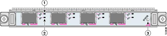
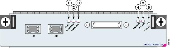
The 1-Port and 3-Port Clear Channel OC-3 ATM SPA has three types of LEDs. There are two LEDs for each port on the SPA, and one STATUS LED. The figure below shows an example of these LEDs on a 3-Port Clear Channel OC-3 ATM SPA.
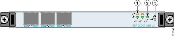
|
1 |
C/A (Carrier/Alarm) LED |
3 |
STATUS LED |
|
2 |
A/L (Active Loopback) LED |
|
|
The 1-Port and 3-Port Clear Channel OC-3 ATM SPA LEDs are described in the table below.
|
LED Label |
Color |
State |
Meaning |
|---|---|---|---|
|
C/A |
Off |
Off |
Port is not enabled by software. |
|
|
Green |
On |
Port is enabled by software, and there is a valid SONET signal without any alarms. |
|
|
Amber |
On |
Port is enabled by software, and there is at least one alarm. |
|
A/L |
Off |
Off |
Port is not enabled by software. |
|
|
Green |
On |
Port is enabled by software, and loopback is off. |
|
|
Amber |
On |
Port is enabled by software, and loopback is on. |
|
STATUS |
Off |
Off |
SPA power is off. |
|
|
Amber |
On |
SPA power is on and good, and SPA is being configured. |
|
|
Green |
On |
SPA is ready and operational. |
1-Port and 3-Port Clear Channel OC-3 ATM SPA Interface Specifications
The physical layer interface for the 1-Port and 3-Port Clear Channel OC-3 ATM SPA is Optical Carrier-3 (OC-3), and the data link layer is designed to comply with ATM specifications. The 1-Port and 3-Port Clear Channel OC-3 ATM SPA provides up to one and three 155-Mbps OC-3 network interfaces, respectively, for all supported platforms.
Each SPA port accepts an SFP module with a duplex LC-type receptacle that allows connection to single-mode or multimode optical fiber.
1-Port and 3-Port Clear Channel OC-3 ATM SPA Cables and Connectors
The 1-Port and 3-Port Clear Channel OC-3 ATM SPA uses a small form-factor pluggable (SFP) optical transceiver module installed in each port for SONET and SDH single-mode and multimode optical fiber connection (see the figure below).
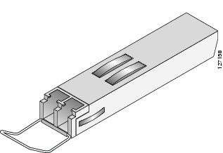
The SFP optical transceiver modules used with the 1-Port and 3-Port Clear Channel OC-3 ATM SPA provide the following optical fiber options:
Use a multimode optical fiber that has a core/cladding diameter of 62.5/125 microns.
Use a single-mode optical fiber that has a modal-field diameter of 8.7 ± 0.5 microns. (Nominal diameter is approximately 10/125 microns.)
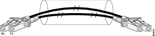
For single-mode and multimode optical fiber connections, you can use either a duplex LC-type cable (see the figure below) or two simplex LC-type cables, one for transmit (TX) and one for receive (RX).
Use a single-mode (for intermediate-reach or long-reach configurations) or multimode optical fiber cable to connect your router to a network or to connect two OC-3-equipped routers back-to-back.
Long-range SFP optical transceiver modules (for long-reach configurations) cannot be connected back-to-back without using an attenuator between them.
1-Port Clear Channel OC-12 ATM SPA Overview
The 1-Port Clear Channel OC-12 ATM SPA is a single-width ATM SPA that can be installed into one SIP subslot. The OC-12 ATM SPA with small form-factor pluggable (SFP) optical transceiver modules provides SONET and SDH network connectivity with a per-port bandwidth of 622.08 Mbps. For more information about SPA bandwidth, see the “Bandwidth Oversubscription” section in this chapter.
The following sections describe the 1-Port Clear Channel OC-12 ATM SPA:
- 1-Port Clear Channel OC-12 ATM SPA LEDs
- 1-Port Clear Channel OC-12 ATM SPA Interface Specifications
- 1-Port Clear Channel OC-12 ATM SPA Cables and Connectors
1-Port Clear Channel OC-12 ATM SPA LEDs
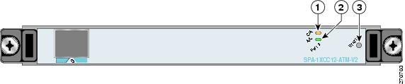
The 1-Port Clear Channel OC-12 ATM SPA has three types of LEDs. There are two LEDs for the port on the SPA, and one STATUS LED, as shown in the figure below.
|
1 |
C/A (Carrier/Alarm) LED |
3 |
STATUS LED |
|
2 |
A/L (Active Loopback) LED |
|
|
The 1-Port Clear Channel OC-12 ATM SPA LEDs are described in the table below.
|
LED Label |
Color |
State |
Meaning |
|---|---|---|---|
|
C/A |
Off |
Off |
Port is not enabled by software. |
|
|
Green |
On |
Port is enabled by software, and there is a valid SONET signal without any alarms. |
|
|
Amber |
On |
Port is enabled by software, and there is at least one alarm. |
|
A/L |
Off |
Off |
Port is not enabled by software. |
|
|
Green |
On |
Port is enabled by software, and loopback is off. |
|
|
Amber |
On |
Port is enabled by software, and loopback is on. |
|
STATUS |
Off |
Off |
SPA power is off. |
|
|
Amber |
On |
SPA power is on and good, and SPA is being configured. |
|
|
Green |
On |
SPA is ready and operational. |
1-Port Clear Channel OC-12 ATM SPA Interface Specifications
The physical layer interface for the 1-Port Clear Channel OC-12 ATM SPA is Optical Carrier-12 (OC-12), and the 1-Port Clear Channel OC-12 ATM SPA is designed to comply with ATM specifications. The 1-Port Clear Channel OC-12 ATM SPA provides one 622.08 Mbps OC-12 network interface for all supported platforms.
The single SPA port accepts an SFP module with a duplex LC-type receptacle that allows connection to single-mode or multimode optical fiber.
1-Port Clear Channel OC-12 ATM SPA Cables and Connectors
The 1-Port Clear Channel OC-12 ATM SPA uses a small form-factor pluggable (SFP) optical transceiver module installed in each port for SONET and SDH single-mode and multimode optical fiber connection (see the figure below).
The 1-Port Clear Channel OC-12 ATM SPA supports the following types of optical transceiver modules:
Multimode (MM) SFP module—SFP-OC12-MM
Short-reach (SR) SFP module—SFP-OC12-SR
Intermediate-reach (IR) SFP module (15 km)—SFP-OC12-IR1
Long-reach (LR) SFP module (40 km)—SFP-OC12-LR1
Long-reach (LR) SFP module (80 km)—SFP-OC12-LR2
The SR, IR, and LR1 transceivers provide a full-duplex 622.08-Mbps, laser-based SONET/SDH- compliant interface with an average wavelength of 1310 nm. The LR2 transceivers provide a full-duplex, 622.08-Mbps, laser-based SONET/SDH-compliant interface with an average wavelength of 1530 nm. The multimode transceiver provides a full-duplex, 622.08-Mbps, LED-based SONET/SDH-compliant interface with an average wavelength of 1325 nm.
The 1-Port Clear Channel OC-12 ATM SPA provides the following optical fiber options:
Use a multimode optical fiber that has a core/cladding diameter of 62.5/125 microns.
- Single-mode—622.08-Mbps, OC-12 optical fiber (SONET STS-12c or SDH STM-4)
Use a single-mode optical fiber that has a modal-field diameter of 8.7 ±0.5 microns. (Nominal diameter is approximately 10/125 microns.)
For single-mode and multimode optical fiber connections, you can use either a duplex LC-type cable (see the figure below) or two simplex LC-type cables, one for transmit (TX) and one for receive (RX).
4-Port and 8-Port OC-3c/STM-1 POS SPA Overview
The 4-Port and 8-Port OC-3c/STM-1 POS SPA is a single-width SPA that installs into one SIP subslot. The OC-3c/STM-1 POS SPA with small form-factor pluggable (SFP) optical transceiver modules provides SONET and SDH network connectivity with a per-port bandwidth of 155.52 Mbps. The 4-Port and 8-Port OC-3c/STM-1 POS SPA operates at quarter rate.
Note | The interconnect between a SIP and a SPA can operate at either 2.5Gbps or 10Gbps. If the maximum capacity of a SPA is greater than 2.5Gbps the interconnect operates at 10Gbps and the SPA is a "full-rate" SPA. If the maximum capacity of a SPA is 2.5Gbps or less the interconnect operates at 2.5Gbps and the SPA is a "quarter-rate" SPA.When SFP modules are replaced, the SPA interface retains any previously defined configurations. These configurations include settings for IP address, clock source, loopback, Cyclic Redundancy Check (CRC), and POS flags. |
For more information about SPA bandwidth, see the “Bandwidth Oversubscription” section in this chapter. For more information about SPAs and their compatibility with SIPs and modular optics, see the “SIP and SPA Product Overview” chapter in this guide.
The following sections describe the 4-Port OC-3c/STM-1 POS SPA:
- 4-Port and 8-Port OC-3c/STM-1 POS SPA LEDs
- 4-Port and 8-Port OC-3c/STM-1 POS SPA Interface Specifications
- 4-Port and 8-Port OC-3c/STM-1 POS SPA Optical Transceiver Modules and Cables
4-Port and 8-Port OC-3c/STM-1 POS SPA LEDs
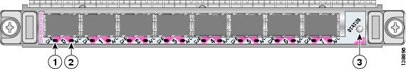
The 4-Port and 8-Port OC-3c/STM-1 POS SPA has three types of LEDs: two LEDs for each port on the SPA and one STATUS LED. The table below shows the 4-Port OC-3c/STM-1 POS SPA.
Note | Two different faceplates exist for either the 4-Port and 8-Port OC-3c/STM-1 POS SPAs. They each contain the same LEDs and the number of ports are 4 and 8 respectively. |
|
1 |
C/A (Carrier/Alarm) LED |
3 |
STATUS LED |
|
2 |
A/L (Active/Loopback) LED |
|
|
The below table describes the 4-Port and 8-Port OC-3c/STM-1 POS SPA LEDs.
|
LED Label |
Color |
State |
Meaning |
|---|---|---|---|
|
C/A |
Off |
Off |
SONET controller is shut down. |
|
Green |
On |
Port is enabled by software, and there is a valid SONET signal without any alarms. |
|
|
Amber |
On |
Port is enabled by software, and there is at least one alarm. |
|
|
A/L |
Off |
Off |
Interface is shut down. |
|
Green |
On |
Port is enabled by software, and loopback is off. |
|
|
Amber |
On |
Port is enabled by software, and loopback is on. |
|
|
STATUS |
Off |
Off |
SPA power is off. |
|
Green |
On |
SPA is ready and operational. |
|
|
Amber |
On |
SPA power is on and good, and the SPA is being configured. |
4-Port and 8-Port OC-3c/STM-1 POS SPA Interface Specifications
The framer processes incoming and outgoing SONET or SDH frames. The framer operates at OC-3c/STM-1 line rates (155.52 Mbps).
Packet data is transported with a user-configured encapsulation (such as Point-to-Point Protocol [PPP]) and is mapped into the STS-3c/STM-1 frame.
The 4-Port and 8-Port OC-3c/STM-1 POS SPA interfaces comply with the following RFCs:
- RFC 1662, PPP in HDLC-like Framing
- RFC 2427, Multiprotocol Interconnect over Frame Relay
- RFC 2615, PPP over SONET/SDH
4-Port and 8-Port OC-3c/STM-1 POS SPA Optical Transceiver Modules and Cables
The 4-Port and 8-Port OC-3c/STM-1 POS SPA uses a small form-factor pluggable (SFP) optical transceiver module installed in each port for SONET and SDH single-mode and multimode optical fiber connection (see the figure below).
Cisco Systems qualifies the optics that are approved for use with its SPAs. The 4-Port OC-3c/STM-1 POS SPA supports the following types of optical transceiver modules:
- Multimode (MM) SFP module—SFP-OC3-MM
- Short-reach (SR) SFP module—SFP-OC3-SR
- Intermediate-reach (IR) SFP module (15 km)—SFP-OC3-IR1
- Long-reach (LR) SFP module (40 km)—SFP-OC3-LR1
- Long-reach (LR) SFP module (80 km)—SFP-OC3-LR2
The SFP optical transceiver modules used with the 4-Port and 8-Port OC-3c/STM-1 POS SPA provide the following optical fiber options:
- Multimode—155-Mbps, OC-3c/STM-1 optical fiber (SONET STS-3c or SDH STM-1)
Use a multimode optical fiber that has a core/cladding diameter of 62.5/125 microns.
- Single-mode—155-Mbps, OC-3c/STM-1 optical fiber (SONET STS-3c or SDH STM-1)
Use a single-mode optical fiber that has a modal-field diameter of 8.7 ± 0.5 microns. (Nominal diameter is approximately 10/125 microns.)
For single-mode and multimode optical fiber connections, you can use either a duplex LC-type cable (see the figure below) or two simplex LC-type cables, one for transmit (TX) and one for receive (RX).
Use single-mode (for intermediate-reach or long-reach configurations) or multimode optical fiber cable to connect your router to a network or to connect two 4-Port or 8-Port OC-3c/STM-1 POS SPA-equipped routers back-to-back.
Long-range SFP optical transceiver modules (for long-reach configurations) cannot be connected back-to-back without using an attenuator between them.
OC-3 Module Connections
The table below shows the OC-3 specifications of the optics on the 4-Port OC-3c/STM-1 POS SPA.
|
Specification |
Description |
|---|---|
|
Wavelength |
OC-3 MM: 1270 nm to 1380 nm OC-3 SR: 1260 nm to 1360 nm OC-3 IR-1: 1261 nm to 1360 nm OC-3 LR-1: 1263 nm to1360 nm OC-3 LR-2: 1480 nm to 1580 nm |
|
Cabling distance (maximum) |
OC-3 MM: 2 km (1.2 miles) OC-3 SR: 2 km (1.2 miles) OC-3 IR-1: 15 km (9.3 miles) OC-3 LR-1: 40 km (24.8 miles) OC-3 LR-2: 80 km (49.7 miles) |
|
Operating case temperature range |
OC-3 MM: 23 to 185 degrees F (–5 to 85 degrees C) OC-3 SR: 23 to 185 degrees F (–5 to 85 degrees C) OC-3 IR-1: 23 to 185 degrees F (–5 to 85 degrees C) OC-3 LR-1: 23 to 185 degrees F (–5 to 85 degrees C) OC-3 LR-2: 23 to 185 degrees F (–5 to 85 degrees C) |
|
TX power |
OC-3 MM: (not supported) OC-3 SR: –15 to –8 dBm OC-3 IR-1: –15 to –8 dBm OC-3 LR-1: –5 to 0 dBm OC-3 LR-2: –5 to 0 dBm |
|
Receiver sensitivity (maximum) |
OC-3 MM: –30 dBm OC-3 SR: –23 dBm OC-3 IR-1: –28 dBm OC-3 LR-1: –34 dBm OC-3 LR-2: –34 dBm |
|
RX overload |
OC-3 MM: –5 dBm OC-3 SR: –8 dBm OC-3 IR-1: –8 dBm OC-3 LR-1: –10 dBm OC-3 LR-2: –10 dBm |
|
Maximum receiver power damage |
OC-3 MM: +5 dBm OC-3 SR: +5 dBm OC-3 IR-1: +5 dBm OC-3 LR-1: +5 dBm OC-3 LR-2: +5 dBm |
4-Port and 8-Port OC-12c/STM-4 Multirate POS SPA Overview
The 4-Port and 8-Port OC-12c/STM-4 Multirate POS SPA is a single-width SPA that installs into one SIP subslot. The SPA with small form-factor pluggable (SFP) optical transceiver modules provides Optical Carrier Level (OC-n ) for SONET and Synchronous Transport Module (STM-n ) for SDH network connectivity. On this SPA, any given port can use either an OC-3 or OC-12 SFP module, so the per-port bandwidth can be either 155.52 Mbps or 622.08 Mbps, respectively, depending on the customer configuration.
Note | When SFP modules are replaced, the SPA interface retains any previously defined configurations. These configurations include settings for IP address, clock source, loopback, CRC, and POS flags. |
For more information about SPA bandwidth, see the “Bandwidth Oversubscription” topic in this chapter. For more information about SPAs and their compatibility with SIPs and modular optics, see the “SIP and SPA Product Overview” chapter in this guide.
The following sections describe the 4-Port and 8-Port OC-12c/STM-4 Multirate POS SPA:
- 4-Port and 8-Port OC-12c/STM-4 Multirate POS SPA LEDs
- 4-Port and 8-Port OC-12c/STM-4 Multirate POS SPA Interface Specifications
- 4-Port and 8-Port OC-12c/STM-4 Multirate POS SPA Optical Transceiver Modules and Cables
4-Port and 8-Port OC-12c/STM-4 Multirate POS SPA LEDs
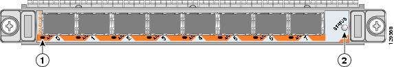
The 4-Port and 8-Port OC-12c/STM-4 Multirate POS SPA has three types of LEDs: two LEDs for each port on the SPA and one STATUS LED.The figure below shows the 8-Port OC-12c/STM-4 Multirate POS SPA faceplate.
Note | Two different faceplates exist for either the 4-Port and 8-Port OC-12c/STM-4 POS SPAs. They each contain the same LEDs and the number of ports are 4 and 8 respectively. |
|
1 |
C/A (Carrier/Alarm) LED |
3 |
STATUS LED |
|
2 |
A/L (Active/Loopback) LED |
|
|
The table below describes the 4-Port and 8-Port OC-12c/STM-4 Multirate POS SPA LEDs.
|
LED Label |
Color |
State |
Meaning |
|---|---|---|---|
|
C/A |
Off |
Off |
SONET controller is shut down. |
|
Green |
On |
Port is enabled by software, and there is a valid SONET signal without any alarms. |
|
|
Amber |
On |
Port is enabled by software, and there is at least one alarm. |
|
|
A/L |
Off |
Off |
Interface is shut down. |
|
Green |
On |
Port is enabled by software, and loopback is off. |
|
|
Amber |
On |
Port is enabled by software, and loopback is on. |
|
|
STATUS |
Off |
Off |
SPA power is off. |
|
Green |
On |
SPA is ready and operational. |
|
|
Amber |
On |
SPA power is on and good, and the SPA is being configured. |
4-Port and 8-Port OC-12c/STM-4 Multirate POS SPA Interface Specifications
The framer processes incoming and outgoing SONET or SDH frames. The framer operates at OC-3 line rates (155.52 Mbps) and OC-12 line rates (622.08 Mbps). Packet data is transported with a user-configured encapsulation (such as Point-to-Point Protocol [PPP]) and is mapped into the Layer 2 frame.
The 4-Port and 8-Port OC-12c/STM-4 Multirate POS SPA interface complies with the following RFCs:
- RFC 1662, PPP in HDLC-like Framing
- RFC 2427, Multiprotocol Interconnect over Frame Relay
- RFC 2615, PPP over SONET/SDH
4-Port and 8-Port OC-12c/STM-4 Multirate POS SPA Optical Transceiver Modules and Cables
The 4-Port and 8-Port OC-12c/STM-4 Multirate POS SPA uses a small form-factor pluggable (SFP) optical transceiver module installed in each port for SONET and SDH single-mode and multimode optical fiber connections (see the figure below).
Cisco Systems qualifies the optics that are approved for use with its SPAs. The following OC-3 optical transceiver modules are supported on the 4-Port and 8-Port OC-12c/STM-4 Multirate POS SPA:
- Multimode (MM) SFP module—SFP-OC3-MM
- Short-reach (SR) SFP module—SFP-OC3-SR
- Intermediate-reach (IR) SFP module (15 km)—SFP-OC3-IR1
- Long-reach (LR) SFP module (40 km)—SFP-OC3-LR1
- Long-reach (LR) SFP module (80 km)—SFP-OC3-LR2
The following OC-12 optical transceiver modules are supported on the 4-Port and 8-Port OC-12c/STM-4 Multirate POS SPA:
- Multimode (MM) SFP module—SFP-OC12-MM
- Short-reach (SR) SFP module—SFP-OC12-SR
- Intermediate-reach (IR) SFP module (15 km)—SFP-OC12-IR1
- Long-reach (LR) SFP module (40 km)—SFP-OC12-LR1
- Long-reach (LR) SFP module (80 km)—SFP-OC12-LR2
The following OC-3 optical fiber options are available for the 8-Port OC-12c/STM-4 Multirate POS SPA:
- Multimode—155.52-Mbps, OC-3 optical fiber (SONET STS-3c or SDH STM-1)
Use a multimode optical fiber that has a core/cladding diameter of 62.5/125 microns.
- Single-mode—155.52-Mbps, OC-3 optical fiber (SONET STS-3c or SDH STM-1)
Use a single-mode optical fiber that has a modal-field diameter of 8.7 ± 0.5 microns. (Nominal diameter is approximately 10/125 microns.)
The following OC-12 optical fiber options are available for the 8-Port OC-12c/STM-4 Multirate POS SPA:
- Multimode—622.08-Mbps, OC-12 optical fiber (SONET STS-12c or SDH STM-4)
Use a multimode optical fiber that has a core/cladding diameter of 62.5/125 microns.
- Single-mode—622.08-Mbps, OC-12 optical fiber (SONET STS-12c or SDH STM-4)
Use a single-mode optical fiber that has a modal-field diameter of 8.7 ± 0.5 microns. (Nominal diameter is approximately 10/125 microns.)
For single-mode and multimode optical fiber connections, you can use either a duplex LC-type cable (see the figure below) or two simplex LC-type cables, one for transmit (TX) and one for receive (RX).
Use single-mode (for short-, intermediate- or long-reach configurations) or multimode optical fiber cable to connect your router to a network or two OC-3-equipped or OC-12-equipped routers back-to-back.
Long-range SFP optical transceiver modules (for long-reach configurations) cannot be connected back-to-back without using an attenuator between them.
OC-3 Module Connections
The table below shows the OC-3 specifications of the optics on the 8-Port OC-12c/STM-4 Multirate POS SPA.
|
Specification |
Description |
|---|---|
|
Wavelength |
OC-3 MM: 1270 nm to 1380 nm OC-3 SR: 1260 nm to 1360 nm OC-3 IR-1: 1261 nm to 1360 nm OC-3 LR-1: 1263 nm to1360 nm OC-3 LR-2: 1480 nm to 1580 nm |
|
Operating case temperature range |
OC-3 MM: 23 to 185 degrees F (–5 to 85 degrees C) OC-3 SR: 23 to 185 degrees F (–5 to 85 degrees C) OC-3 IR-1: 23 to 185 degrees F (–5 to 85 degrees C) OC-3 LR-1: 23 to 185 degrees F (–5 to 85 degrees C) OC-3 LR-2: 23 to 185 degrees F (–5 to 85 degrees C) |
|
Cabling distance (maximum) |
OC-3 MM: 2 km (1.2 miles) OC-3 SR: 2 km (1.2 miles) OC-3 IR-1: 15 km (9.3 miles) OC-3 LR-1: 40 km (24.8 miles) OC-3 LR-2: 80 km (49.7 miles) |
|
TX power |
OC-3 MM: (not supported) OC-3 SR: –15 to –8 dBm OC-3 IR-1: –15 to –8 dBm OC-3 LR-1: –5 to 0 dBm OC-3 LR-2: –5 to 0 dBm |
|
Receiver sensitivity (maximum) |
OC-3 MM: –30 dBm OC-3 SR: –23 dBm OC-3 IR-1: –28 dBm OC-3 LR-1: –34 dBm OC-3 LR-2: –34 dBm |
|
RX overload |
OC-3 MM: –5 dBm OC-3 SR: –8 dBm OC-3 IR-1: –8 dBm OC-3 LR-1: –10 dBm OC-3 LR-2: –10 dBm |
|
Maximum receiver power damage |
OC-3 MM: +5 dBm OC-3 SR: +5 dBm OC-3 IR-1: +5 dBm OC-3 LR-1: +5 dBm OC-3 LR-2: +5 dBm |
OC-12 Module Connections
The table below shows the OC-12 specifications of the optics on the 8-Port OC-12c/STM-4 Multirate POS SPA.
|
Specification |
Description |
|---|---|
|
Wavelength |
OC-12 MM: 1270 nm to 1380 nm OC-12 SR: 1261 nm to 1360 nm OC-12 IR-1: 1293 nm to 1334 nm OC-12 LR-1: 1280 nm to 1335 nm OC-12 LR-2: 1480 nm to 1580 nm |
|
Cabling distance (maximum) |
OC-12 MM: 0.5 km (0.3 miles) OC-12 SR: 2 km (1.2 miles) OC-12 IR-1: 15 km (9.3 miles) OC-12 LR-1: 40 km (24.8 miles) OC-12 LR-2: 80 km (49.7 miles) |
|
Operating case temperature range |
OC-12 MM: 23 to 185 degrees F (–5 to 85 degrees C) OC-12 SR: 23 to 185 degrees F (–5 to 85 degrees C) OC-12 IR-1: 23 to 185 degrees F (–5 to 85 degrees C) OC-12 LR-1: 23 to 185 degrees F (–5 to 85 degrees C) OC-12 LR-2: 23 to 185 degrees F (–5 to 85 degrees C) |
|
TX power |
OC-12 MM: (not supported) OC-12 SR: –15 to –8 dBm OC-12 IR-1: –15 to –8 dBm OC-12 LR-1: –3 to 2 dBm OC-12 LR-2: –3 to 2 dBm |
|
Receiver sensitivity (maximum) |
OC-12 MM: –26 dB OC-12 SR: –23 dBm OC-12 IR-1: –28 dBm OC-12 LR-1: –28 dBm OC-12 LR-2: –28 dBm |
|
RX overload |
OC-12 MM: –6 dBm OC-12 SR: –8 dBm OC-12 IR-1: –8 dBm OC-12 LR-1: –8 dBm OC-12 LR-2: –8 dBm |
|
Maximum receiver power damage |
OC-12 MM: +5 dBm OC-12 SR: +5 dBm OC-12 IR-1: +5 dBm OC-12 LR-1: +5 dBm OC-12 LR-2: +5 dBm |
2-Port and 4-Port OC-48c/STM-16 POS/RPR SPA Overview
The following sections describe the 2-Port and 4-Port OC-48c/STM-16 POS/RPR SPA:
- 2-Port and 4-Port OC-48c/STM-16 POS/RPR SPA LEDs
- 2-Port and 4-Port OC-48c/STM-16 POS/RPR SPA Interface Specifications
- 2-Port and 4-Port OC-48c/STM-16 POS/RPR SPA Cables, Optical Transceiver Modules, and Connectors
2-Port and 4-Port OC-48c/STM-16 POS/RPR SPA LEDs
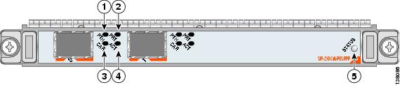
The 2-Port and 4-Port OC-48c/STM-16 POS/RPR SPA has five types of LEDs: four LEDs for each port on the SPA and one STATUS LED, as shown in the figure below.
|
1 |
PTH (Pass Through) LED |
4 |
ACT (Active Loopback) LED |
|
2 |
PRT (Protect) LED |
5 |
STATUS LED |
|
3 |
CAR (Carrier Alarm) LED |
|
|
The table below describes the 2-Port and 4-Port OC-48c/STM-16 POS/RPR SPA LEDs.
|
LED Label |
Color |
State |
Meaning |
|---|---|---|---|
|
PTH |
Off |
Off |
Port is not in pass-through mode. |
|
|
Green |
On |
Port is in pass-through mode. |
|
CAR |
Off |
Off |
Port is not enabled by software. |
|
|
Green |
On |
Port is enabled by software, and there is a valid SONET signal without any alarms. |
|
|
Amber |
On |
Port is enabled by software, and there is at least one alarm. |
|
|
Amber |
Flashing |
Port is enabled by software, and there is a side mismatch. |
|
PRT |
Off |
Off |
Port is not wrapped or steering. |
|
|
Green |
On |
A node on the ring is wrapped. |
|
|
Green |
Flashing |
A node on the ring is steering. |
|
|
Amber |
On |
Port is locally wrapped. |
|
|
Amber |
Flashing |
Port is locally steering. |
|
ACT |
Off |
Off |
Port is not enabled by software. |
|
|
Green |
On |
Port is enabled by software, and loopback is off. |
|
|
Amber |
On |
Port is enabled by software, and loopback is on. |
|
STATUS |
Off |
Off |
SPA power is off. |
|
|
Green |
On |
SPA is ready and operational. |
|
|
Amber |
On |
SPA power is on and good, and the SPA is being configured. |
2-Port and 4-Port OC-48c/STM-16 POS/RPR SPA Interface Specifications
The physical layer interface for the 2-Port and 4-Port OC-48c/STM-16 POS/RPR SPA is Optical Carrier-48 (OC-48), which provides SONET and SDH network connectivity with a per-port bandwidth of 2.488 Gbps.
Each port on the 2-Port and 4-Port OC-48c/STM-16 POS/RPR SPA has one duplex LC-type receptacle that allows connection to single-mode optical fiber.
Note | For Cisco IOS XR Software Release 3.8.0, the 2-Port and 4-Port OC-48c/STM-16 POS/RPR SPA supports Dynamic Packet Transport (DPT) feature. Cisco DPT family of products delivers scalable Internet service, reliable IP-aware optical transport, and simplified network operations. The Spatial Reuse Protocol (SRP) is a MAC-layer protocol developed by Cisco and is used in conjunction with Cisco DPT products, which utilizes a pair of counter-rotating rings in an optimum fashion to provide improved bandwidth utilization over an equivalent SONET network. |
2-Port and 4-Port OC-48c/STM-16 POS/RPR SPA Cables, Optical Transceiver Modules, and Connectors
Use single-mode optical fiber cable (for intermediate-reach configurations) to connect your router to a network or to connect two OC-48-equipped routers back to back.
The 2-Port and 4-Port OC-48c/STM-16 POS/RPR SPA supports the following types of optical transceiver modules:
- Single-mode short-reach (SR) SFP module—SFP-OC48-SR OC48/STM16c
- Single-mode intermediate-reach (IR) SFP module—SFP-OC48-IR1 OC48/STM16c
- Single-mode long-reach (LR) SFP module—SFP-OC48-LR2 OC48/STM16c
Each port on the 2-Port and 4-Port OC-48c/STM-16 POS/RPR SPA has one duplex LC-type receptacle. For single-mode optical fiber connections, you can use either a duplex LC-type cable (see the figure below) or two simplex LC-type cables, one for transmit (TX) and one for receive (RX).
Use a single-mode optical fiber that has a modal-field diameter of 8.7 ±0.5 microns (nominal diameter is approximately 10/125 microns) to connect your router to a network.
The figure below shows the cable type for use with the XFP optical transceiver module on the 1-Port 10-Gigabit Ethernet SPA.
OC-48 Module Connections
The table below shows the OC-48 specifications for use with the 2-Port and 4-Port OC-48c/STM-16 POS/RPR SPA.
|
Specification |
Description |
|---|---|
|
Wavelength |
OC-48 SR: 1266 nm to 1360 nm OC-48 IR-1: 1260 nm to 1360 nm OC-48 LR-2: 1500 nm to 1580 nm |
|
Cabling distance (maximum) |
OC-48 SR: 2 km (1.2 miles) OC-48 IR-1: 15 km (9.3 miles) OC-48 LR-2: 80 km (49.7 miles) |
|
Operating case temperature range |
OC-48 SR: 23 to 158 degrees F (–5 to 70 degrees C) OC-48 IR-1: 23 to 158 degrees F (–5 to 70 degrees C) OC-48 LR-2: 23 to 158 degrees F (–5 to 70 degrees C) |
|
TX power |
OC-48 SR: –10 to –3 dBm OC-48 IR-1: –5 to 0 dBm OC-48 LR-2: –2 to +3 dBm |
|
Receiver sensitivity (maximum) |
OC-48 SR: –18 dBm OC-48 IR-1: –18 dBm OC-48 LR-2: –28 dBm |
|
RX overload |
OC-48 SR: –3 dBm OC-48 IR-1: 0 dBm OC-48 LR-2: –9 dBm |
|
Maximum receiver power damage |
OC-48 SR: +5 dBm OC-48 IR-1: +5 dBm OC-48 LR-2: +5 dBm |
1-Port OC-192c/STM-64 POS/RPR XFP SPA Overview
The 1-Port OC-192c/STM-64 POS/RPR XFP SPA is a single-height SPA that is installed in one SIP subslot. The 1-Port OC-192c/STM-64 POS/RPR XFP SPA provides SONET and SDH network connectivity with a bandwidth of 9.95 Gbps.
For more information about SPA bandwidth, see the “Bandwidth Oversubscription” section in this chapter. For more information about SPAs and their compatibility with SIPs and modular optics, see the product overview chapter in this guide.
The 1-Port OC-192c/STM-64 POS/RPR XFP SPA uses a 10-Gbps small form-factor pluggable optical receptacle for each port allowing connection to single-mode optical fiber. For more information on the optical fiber cables used with this SPA, see the 1-Port OC-192c/STM-64 POS/RPR XFP SPA Optical Transceiver Modules, Connectors, and Cables.
The following sections describe the 1-Port OC-192c/STM-64 POS/RPR XFP SPA:
- 1-Port OC-192c/STM-64 POS/RPR XFP SPA LEDs
- 1-Port OC-192c/STM-64 POS/RPR XFP SPA Interface Specifications
- 1-Port OC-192c/STM-64 POS/RPR XFP SPA Optical Transceiver Modules, Connectors, and Cables
1-Port OC-192c/STM-64 POS/RPR XFP SPA LEDs
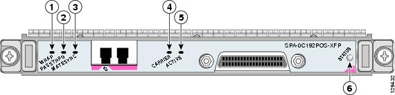
The 1-Port OC-192c/STM-64 POS/RPR XFP SPA has six LEDs, as shown in the figure below.
|
1 |
WRAP LED |
4 |
CARRIER LED |
|
2 |
PASSTHRU LED |
5 |
ACTIVE LED |
|
3 |
MATESYNC LED |
6 |
STATUS LED |
The table below describes the 1-Port OC-192c/STM-64 POS/RPR XFP SPA LEDs.
|
LED Label |
Color |
State |
Meaning |
|---|---|---|---|
|
WRAP |
Off |
Off |
Port is not in wrap mode. |
|
Green |
On |
Port is in wrap mode somewhere on the ring. |
|
|
Amber |
On |
Port is in wrap mode locally. |
|
|
PASSTHRU |
Off |
Off |
Port is not in pass-through mode. |
|
Amber |
On |
Port is in pass-through mode. |
|
|
MATESYNC |
Off |
Off |
Mate port is not synchronized. |
|
Green |
On |
Mate port is synchronized. |
|
|
CARRIER |
Off |
Off |
Port is not enabled by software. |
|
Green |
On |
Port is enabled by software, and there is a valid SONET signal without alarms. |
|
|
Amber |
On |
Port is enabled by software, and there is at least one alarm (LOS, LOF, RDI, and so on). |
|
|
Blinking |
SRP mode mismatch alarm is indicated. |
||
|
ACTIVE |
Off |
Off |
Port is not enabled by software. |
|
Green |
On |
Port is enabled by software, and loopback is off. |
|
|
Amber |
On |
Port is enabled by software, and loopback is on. |
|
|
STATUS |
Off |
Off |
SPA power off. |
|
Green |
On |
SPA is ready and operational. |
|
|
Amber |
On |
SPA power is on and good, and the SPA is being configured. |
1-Port OC-192c/STM-64 POS/RPR XFP SPA Interface Specifications
The framer processes incoming and outgoing SONET or SDH frames. The framer operates at OC-192c/STM-64 line rates (9.95 Gbps).
Packet data is transported with a user-configured encapsulation (such as Point-to-Point Protocol [PPP]) and is mapped into the STS-192c/STM-64 frame.
The 1-Port OC-192c/STM-64 POS/RPR XFP SPA interface is compliant with the following RFCs:
For information on SNMP MIB support, see the Implementing SNMP on Cisco IOS XR Software chapter in Cisco IOS XR System Management Configuration Guide
Note | For Cisco IOS XR Software Release 3.8.0, the 1-Port OC-192c/STM-64 POS/RPR XFP SPA supports the Dynamic Packet Transport (DPT) feature. The Cisco DPT family of products delivers scalable Internet service, reliable IP-aware optical transport, and simplified network operations. The Spatial Reuse Protocol (SRP) is a MAC-layer protocol developed by Cisco and is used in conjunction with Cisco DPT products, which use a pair of counter-rotating rings in an optimum fashion to provide improved bandwidth utilization over an equivalent SONET network. |
1-Port OC-192c/STM-64 POS/RPR XFP SPA Optical Transceiver Modules, Connectors, and Cables
The 1-Port OC-192c/STM-64 POS/RPR XFP SPA uses a single-mode, 9.95 Gbps, OC-192c optical fiber (SONET STS-192c or SDH STM-64) optical transceiver module for SONET and SDH connection to the network.
The 1-Port OC-192c/STM-64 POS/RPR XFP SPA supports the following types of optical transceiver module:
- Single-mode short-reach (SR) XFP module—XFP-10GLR-OC192SR
- Single-mode intermediate-reach (IR) XFP module—XFP-10GER-OC192IR
- Single-mode very-long reach XFP module—XFP-10GZR-OC192LR
Cisco Systems qualifies the optics that are approved for use with its SPAs. As of Cisco IOS XR Software Release 3.4.0, the above-listed XFPs are the only optical transceiver modules qualified for use.
Use a single-mode optical fiber that has a modal-field diameter of 8.7 ±0.5 microns (nominal diameter is approximately 10/125 microns) to connect your router to a network.
The figure below shows the cable type for use with the XFP optical transceiver module on the 1-Port OC-192c/STM-64 POS/RPR XFP SPA.
OC-192 Module Connections
The table below shows the OC-192 specifications for use with the 1-Port OC-192c/STM-64 POS/RPR XFP SPA.
|
Specification |
Description |
|---|---|
|
Wavelength |
OC-192 SR-1: 1290 nm to 1330 nm OC-192 IR-2: 1530 nm to 1565 nm OC-192 LR-2: 1530 nm to 1565 nm |
|
Cabling distance (maximum) |
OC-192 SR-1: 2 km (1.2 miles) OC-192 IR-2: 40 km (24.8 miles) OC-192 LR-2: 50 miles (80 km) |
|
Operating case temperature range |
OC-192 SR-1: 23 to 158 degrees F (–5 to 70 degrees C) OC-192 IR-2: 23 to 158 degrees F (–5 to 70 degrees C) OC-192 LR-2: 23 to 158 degrees F (–5 to 70 degrees C) |
|
Tx Power |
OC-192 SR-1: –6 dBm –1 dBm OC-192 IR-2: –1 dBm +2 dBm OC-192 LR-2: 0 to +4 dBm |
|
Receiver Sensitivity (maximum) |
OC-192 SR-1: –11 dBm OC-192 IR-2: –14 dBm OC-192 LR-2: –24 dBm |
|
RX Overload |
OC-192 SR-1: –1 dBm OC-192 IR-2: +2 dBm OC-192 LR-2: –7.0 dBm |
|
Maximum Receiver Power Damage |
OC-192 SR-1: +5 dBm OC-192 IR-2: +5 dBm OC-192 LR-2: +5 dBm |
Note | The RPR mate cable is necessary only when the SPA is to be used in RPR mode. It is not needed in POS mode. Support for the RPR feature is dependent on the platform software-release feature content. Verify support for the RPR feature support using SPA datasheets or by contacting your Cisco representative. |
1-Port OC-192c/STM-64 POS/RPR VSR Optics SPA Overview
The 1-Port OC-192c/STM-64 POS/RPR VSR Optics SPA is a double-height SPA that is installed in a SIP subslot. The 1-Port OC-192c/STM-64 POS/RPR VSR Optics SPA provides SONET and SDH network connectivity with a bandwidth of 9.95 Gbps.
For more information about SPA bandwidth, see the “Bandwidth Oversubscription” section in this chapter. For more information about SPAs and their compatibility with SIPs and modular optics, see the “SIP and SPA Product Overview” chapter in this guide.
The 1-Port OC-192c/STM-64 POS/RPR VSR Optics SPA uses a single, 10-Gbps fixed optical receptacle, allowing a connection to multimode optical fiber. For more information on the optical fiber cables used with this SPA, see the 1-Port OC-192c/STM-64 POS/RPR VSR Optics SPA Fixed Optical Transceiver, Connector, and Cables.
The following sections describe the 1-Port OC-192c/STM-64 POS/RPR VSR Optics SPA:
- 1-Port OC-192c/STM-64 POS/RPR VSR Optics SPA LEDs
- 1-Port OC-192c/STM-64 POS/RPR VSR Optics SPA Interface Specifications
- 1-Port OC-192c/STM-64 POS/RPR VSR Optics SPA Fixed Optical Transceiver, Connector, and Cables
1-Port OC-192c/STM-64 POS/RPR VSR Optics SPA LEDs
The 1-Port OC-192c/STM-64 POS/RPR VSR Optics SPA has six LEDs, as shown in the figure below.
|
1 |
WRAP LED |
4 |
CARRIER LED |
|
2 |
PASSTHRU LED |
5 |
ACTIVE LED |
|
3 |
MATESYNC LED |
6 |
STATUS LED |
Note | The WRAP, PASSTHRU, and MATESYNC LEDs apply to the SPA in RPR/SRP mode only. |
The table below describes the 1-Port OC-192c/STM-64 POS/RPR VSR Optics SPA LEDs.
|
LED Label |
Color |
State |
Meaning |
|---|---|---|---|
|
WRAP |
Off |
Off |
Port is not in wrap mode. |
|
|
Green |
On |
Port is in wrap mode somewhere on the ring. |
|
|
Amber |
On |
Port is in wrap mode locally. |
|
PASSTHRU |
Off |
Off |
Port is not in pass-through mode. |
|
|
Amber |
On |
Port is in pass-through mode. |
|
MATESYNC |
Off |
Off |
Mate port is not synchronized. |
|
|
Green |
On |
Mate port is synchronized. |
|
CARRIER |
Off |
Off |
Port is not enabled by software. |
|
|
Green |
On |
Port is enabled by software, and there is a valid SONET signal without alarms. |
|
|
Amber |
On |
Port is enabled by software, and there is at least one alarm (LOS, LOF, RDI, and so on). |
|
|
|
Blinking |
SRP mode mismatch alarm is indicated. |
|
ACTIVE |
Off |
Off |
Port is not enabled by software. |
|
|
Green |
On |
Port is enabled by software, and loopback is off. |
|
|
Amber |
On |
Port is enabled by software, and loopback is on. |
|
STATUS |
Off |
Off |
SPA power off. |
|
|
Green |
On |
SPA is ready and operational. |
|
|
Amber |
On |
SPA power is on and good, and the SPA is being configured. |
1-Port OC-192c/STM-64 POS/RPR VSR Optics SPA Interface Specifications
The 1-Port OC-192c/STM-64 POS/RPR VSR Optics SPA contains a SONET/SDH framer to process incoming and outgoing SONET or SDH frames. The framer operates at OC-192/STM-64 line rates (9.95 Gbps).
Packet data is transported with a user-configured encapsulation (such as Point-to-Point Protocol [PPP]) and is mapped into the STS-192c/STM-64 frame.
The 1-Port OC-192c/STM-64 POS/RPR VSR Optics SPA interface is compliant with the following RFCs:
For information on SNMP MIB support, see Implementing SNMP on Cisco IOS XR Software in Cisco IOS XR System Management Configuration Guide
1-Port OC-192c/STM-64 POS/RPR VSR Optics SPA Fixed Optical Transceiver, Connector, and Cables
The 1-Port OC-192c/STM-64 POS/RPR VSR Optics SPA uses fixed optical transceivers, one for receive (RX) and one for transmit (TX), for SONET and SDH connection to the network. Only Very Short Reach (VSR) optics are supported.
The 1-Port OC-192c/STM-64 POS/RPR VSR Optics SPA uses multimode MTP-type connectors:
Multimode—9.95 Gbps, OC-192 optical fiber (SONET STS-192c or SDH STM-64c). Use a multimode optical fiber that has a modal-field diameter of 8.7 ±0.5 microns. (Nominal diameter is approximately 10/125 microns.)
Use a multimode optical fiber cable to connect your router to a network.
The figure below shows the cable type for use with the fixed optical transceiver module on the 1-Port OC-192c/STM-64 POS/RPR VSR Optics SPA.
5-Port Gigabit Ethernet SPA Overview
The following sections describe the 5-Port Gigabit Ethernet SPA:
5-Port Gigabit Ethernet SPA LEDs
The 5-Port Gigabit Ethernet SPA has two types of LEDs: an A/L LED for each individual port and a STATUS LED for the SPA, as shown in the table below.
|
1 |
A/L (Active/Link) LED |
2 |
STATUS LED |
The table below describes the 5-Port Gigabit Ethernet SPA LEDs.
|
LED Label |
Color |
State |
Meaning |
|---|---|---|---|
|
A/L |
Off |
Off |
Port is not enabled. |
|
|
Green |
On |
Port is enabled and the link is up. |
|
|
Amber |
On |
Port is enabled and the link is down. |
|
STATUS |
Off |
Off |
SPA power is off. |
|
|
Green |
On |
SPA is ready and operational. |
|
|
Amber |
On |
SPA power is on and good, and the SPA is being configured. |
5-Port Gigabit Ethernet SPA Cables and Connectors
The 5-Port Gigabit Ethernet SPA has five electrical connectors that support SFP modules. Each port can send and receive traffic using cabling appropriate for the SFP module inserted.
SFP Module Connections
The small form-factor pluggable (SFP) module is an input/output (I/O) device that plugs into the Gigabit Ethernet ports on the 5-Port Gigabit Ethernet SPA, linking the port with a fiber-optic network.
Note | The 5-Port Gigabit Ethernet SPA accepts only the SFP modules listed as supported in this document. An SFP module check is run every time an SFP module is inserted into the 5-Port Gigabit Ethernet SPA, and only SFP modules that pass this check can be used by the 5-Port Gigabit Ethernet SPA. SFP modules exist for technologies other than Gigabit Ethernet and for products other than the 5-Port Gigabit Ethernet SPA. However, the information in this document pertains only to SFP modules that plug into the 5-Port Gigabit Ethernet SPA ports. |
The SFP module has a receiver port (RX) and a transmitter port (TX) that compose one optical interface. The tables below provide SFP module information and specifications.
|
SFP Module Product Number |
SFP Module |
Description |
|---|---|---|
|
SFP-GE-S |
Short wavelength (1000BASE-SX) |
Contains a Class 1 laser of 850 nm for 1000BASE-SX (short-wavelength) applications. |
|
SFP-GE-L |
Long wavelength/long haul (1000BASE-LX/LH) |
Contains a Class 1 laser of 1310 nm for 1000BASE-LX/LH (long-wavelength) applications. |
|
SFP-GE-Z |
Extended wavelength (1000BASE-ZX) |
Contains a Class 1 laser of 1550 nm for 1000BASE-ZX (extended-wavelength) applications. |
|
SFP-GE-T |
RJ-45 copper SFP module (1000BASE-T) |
Provides full-duplex Gigabit Ethernet connectivity to high-end workstations and between wiring closets over an existing copper network infrastructure. |
|
Specification |
Description |
|---|---|
|
Wavelength |
SFP-GE-S: 770 to 860 nm SFP-GE-L: 1270 to 1355 nm SFP-GE-Z: 1500 to 1580 nm SFP-GE-T: N/A |
|
Cabling distance (maximum) |
SFP-GE-S: 500 m on 50/125um MMF; 300 m on 62.5/125um MMFSFP-GE-L: 6.2 miles (10 km)SFP-GE-Z: 49.7 miles (80 km)SFP-GE-T: 328 ft. (100 m) |
|
Operating case temperature range |
SFP-GE-S: 23 to 185 degrees F (–5 to 85 degrees C) SFP-GE-L: 23 to 185 degrees F (–5 to 85 degrees C) SFP-GE-Z: 23 to 185 degrees F (–5 to 85 degrees C) |
|
Storage temperature range |
SFP-GE-S: –40 to 185 degrees F (–40 to 85 degrees C) SFP-GE-L: –40 to 185 degrees F (–40 to 85 degrees C) SFP-GE-Z: –40 to 185 degrees F (–40 to 85 degrees C) |
|
Supply voltage range |
SFP-GE-S: 3.1 to 3.5 VSFP-GE-L: 3.1 to 3.5 VSFP-GE-Z: 3.1 to 3.5 V |
SFP-GE-S Modules
The 1000BASE-SX (short-wavelength) module operates on standard multimode fiber-optic link spans of up to 500 m on 50/125um multimode fiber (MMF) and 300 m on 62.5/125um MMF.
SFP-GE-L Modules
The 1000BASE-LX/LH (long-wavelength/long-haul) module interfaces fully comply with theIEEE 802.3z 1000BASE-LX standard. However, their higher optical quality allows them to reach 6.2 miles (10 km) over single-mode fiber (SMF) versus the 3.1 miles (5 km) specified in the standard.
SFP-GE-Z Modules
The 1000BASE-ZX (extended wavelength) module operates on ordinary single-mode fiber-optic link spans of up to 49.7 miles (80 km). Link spans of up to 62.1 miles (100 km) are possible using premium single-mode fiber or dispersion-shifted single-mode fiber. (Premium single-mode fiber has a lower attenuation per unit length than ordinary single-mode fiber; dispersion-shifted single-mode fiber has both lower attenuation and less dispersion.)
The 1000BASE-ZX module must be coupled to single-mode fiber-optic cable, which is the type of cable typically used in long-haul telecommunications applications. The 1000BASE-ZX module does not operate correctly when coupled to multimode fiber, and it is not intended to be used in environments in which multimode fiber is frequently used (for example, building backbones or horizontal cabling).
The 1000BASE-ZX module is intended to be used as a Physical Medium Dependent (PMD) component for Gigabit Ethernet interfaces found on various switch and router products. It operates at a signaling rate of 1250 Mbaud, transmitting and receiving 8B/10B encoded data.
When shorter lengths of single-mode fiber are used, it may be necessary to insert an inline optical attenuator in the link to avoid overloading the receiver. Use the following guidelines:
- Insert a 10-dB inline optical attenuator between the fiber-optic cable plant and the receiving port on the 1000BASE-ZX module at each end of the link whenever the fiber-optic cable span is less than 15.5 miles (25 km).
- Insert a 5-dB inline optical attenuator between the fiber-optic cable plant and the receiving port on the 1000BASE-ZX module at each end of the link whenever the fiber-optic cable span is equal to or greater than 15.5 miles (25 km) but less than 31 miles (50 km).
SFP-GE-T Modules
The SFP-GE-T (1000BASE-T copper SFP module) provides full-duplex Gigabit Ethernet connectivity to high-end workstations and between wiring closets over an existing copper network infrastructure. The SFP-GE-T maximum cabling distance is 328 feet (100 m).
SFP Module Cabling and Connection Equipment
The table below provides cabling specifications for the SFP modules that can be installed on the 5-Port Gigabit Ethernet SPA. Note that all SFP ports have LC-type connectors.
The minimum cable distance for the SFP-GE-S is 6.5 feet (2 m), and the minimum link distance for the SFP-GE-Z is 6.2 miles (10 km) with an 8-dB attenuator installed at each end of the link. Without attenuators, the minimum link distance for the SFP-GE-Z is 24.9 miles (40 km).
|
SFP Modules |
Wavelength (nm) |
Fiber Type |
Core Size (micron) |
Modal Bandwidth (MHz/km) |
MaximumCable Distance |
||
|---|---|---|---|---|---|---|---|
|
SFP-GE-S |
850 |
|
62.5 |
160 |
722 ft (220 m) |
||
|
|
62.5 |
200 |
984 ft (300 m) |
||||
|
|
50.0 |
400 |
1640 ft (500 m) |
||||
|
|
50.0 |
500 |
1804 ft (550 m) |
||||
|
SFP-GE-L |
1300 |
SMF |
62.5 |
500 |
1804 ft (550 m) |
||
|
|
50.0 |
400 |
1804 ft (550 m) |
||||
|
|
50.0 |
500 |
1804 ft (550 m) |
||||
|
|
9/10 |
— |
6.2 miles (10 km) |
||||
|
SFP-GE-Z |
1550 |
SMF |
9/10 |
— |
49.7 miles (80 km) |
||
|
|
|
8 |
— |
62.1 miles (100 km) |
|||
|
SFP-GE-T |
N/A |
Copper |
N/A |
N/A |
328 ft. (100 m) |
Note | The 1000BASE-ZX SFP modules provide an optical power budget of 21.5 dB. You should measure your cable plant with an optical loss test set to verify that the optical loss of the cable plant (including connectors and splices) is less than or equal to 21.5 dB. The optical loss measurement must be performed with a 1550-nm light source. |
8-Port Gigabit Ethernet SPA Overview
The following sections describe the 8-Port Gigabit Ethernet SPA:
8-Port Gigabit Ethernet SPA LEDs
The 8-Port Gigabit Ethernet SPA has two types of LEDs: an A/L LED for each individual port and a STATUS LED for the SPA, as shown in the figure below.
|
1 |
A/L (Active/Link) LED |
2 |
STATUS LED |
The table below describes the 8-Port Gigabit Ethernet SPA LEDs.
|
LED Label |
Color |
State |
Meaning |
|---|---|---|---|
|
A/L |
Off |
Off |
Port is not enabled. |
|
Green |
On |
Port is enabled and the link is up. |
|
|
Amber |
On |
Port is enabled and the link is down. |
|
|
STATUS |
Off |
Off |
SPA power is off. |
|
Green |
On |
SPA is ready and operational. |
|
|
Amber |
On |
SPA power is on and good, and the SPA is being configured. |
8-Port Gigabit Ethernet SPA Cables and Connectors
The interface connectors on the 8-Port Gigabit Ethernet SPA are eight individual fiber-optic receivers that support SFP modules. Each port can send and receive traffic using the optical fiber connections.
SFP Module Connections
The small form-factor pluggable (SFP) module is an input/output (I/O) device that plugs into the Gigabit Ethernet ports on the 8-Port Gigabit Ethernet SPA, linking the port with a fiber-optic network.
Note | The 8-Port Gigabit Ethernet SPA accepts only the SFP modules listed as supported in this document. An SFP module check is run every time an SFP module is inserted into the 8-Port Gigabit Ethernet SPA, and only SFP modules that pass this check can be used by the 8-Port Gigabit Ethernet SPA. SFP modules exist for technologies other than Gigabit Ethernet and for products other than the 8-Port Gigabit Ethernet SPA. However, the information in this document pertains only to SFP modules that plug into the 8-Port Gigabit Ethernet SPA ports. |
The SFP module has a receiver port (RX) and a transmitter port (TX) that compose one optical interface. The tables below provide SFP module information and specifications.
|
SFP Module Product Number |
SFP Module |
Description |
|---|---|---|
|
SFP-GE-S |
Short wavelength (1000BASE-SX) |
Contains a Class 1 laser of 850 nm for 1000BASE-SX (short-wavelength) applications. |
|
SFP-GE-L |
Long wavelength/long haul (1000BASE-LX/LH) |
Contains a Class 1 laser of 1310 nm for 1000BASE-LX/LH (long-wavelength) applications. |
|
SFP-GE-Z |
Extended wavelength (1000BASE-ZX) |
Contains a Class 1 laser of 1550 nm for 1000BASE-ZX (extended-wavelength) applications. |
|
Specification |
Description |
|---|---|
|
Wavelength |
SFP-GE-S: 770 to 860 nmSFP-GE-L: 1270 to 1355 nmSFP-GE-Z: 1500 to 1580 nm |
|
Cabling distance (maximum) |
SFP-GE-S: 500 m on 50/125um MMF; 300 m on 62.5/125um MMFSFP-GE-L: 6.2 miles (10 km)SFP-GE-Z: 49.7 miles (80 km) |
|
Operating case temperature range |
SFP-GE-S: 23 to 185 degrees F (–5 to 85 degrees C)SFP-GE-L: 23 to 185 degrees F (–5 to 85 degrees C)SFP-GE-Z: 23 to 185 degrees F (–5 to 85 degrees C) |
|
Storage temperature range |
SFP-GE-S: –40 to 185 degrees F (–40 to 85 degrees C)SFP-GE-L: –40 to 185 degrees F (–40 to 85 degrees C)SFP-GE-Z: –40 to 185 degrees F (–40 to 85 degrees C) |
|
Supply voltage range |
SFP-GE-S: 3.1 to 3.5 VSFP-GE-L: 3.1 to 3.5 VSFP-GE-Z: 3.1 to 3.5 V |
SFP-GE-S Modules
The 1000BASE-SX (short-wavelength) module operates on standard multimode fiber-optic link spans of up to 500 m on 50/125um multimode fiber (MMF) and 300 m on 62.5/125um MMF.
SFP-GE-L Modules
The 1000BASE-LX/LH (long-wavelength/long-haul) module interfaces fully comply with the IEEE 802.3z 1000BASE-LX standard. However, their higher optical quality allows them to reach 6.2 miles (10 km) over single-mode fiber (SMF) versus the 3.1 miles (5 km) specified in the standard.
SFP-GE-Z Modules
The 1000BASE-ZX (extended-wavelength) module operates on ordinary single-mode fiber-optic link spans of up to 49.7 miles (80 km). Link spans of up to 62.1 miles (100 km) are possible using premium single-mode fiber or dispersion-shifted single-mode fiber. (Premium single-mode fiber has a lower attenuation per unit length than ordinary single-mode fiber; dispersion-shifted single-mode fiber has both lower attenuation and less dispersion.)
The 1000BASE-ZX module must be coupled to single-mode fiber-optic cable, which is the type of cable typically used in long-haul telecommunications applications. The 1000BASE-ZX module does not operate correctly when coupled to multimode fiber, and it is not intended to be used in environments in which multimode fiber is frequently used (for example, building backbones or horizontal cabling).
The 1000BASE-ZX module is intended to be used as a Physical Medium Dependent (PMD) component for Gigabit Ethernet interfaces found on various switch and router products. It operates at a signaling rate of 1250 Mbaud, transmitting and receiving 8B/10B encoded data.
When shorter lengths of single-mode fiber are used, it may be necessary to insert an inline optical attenuator in the link to avoid overloading the receiver. Use the following guidelines:
- Insert a 10-dB inline optical attenuator between the fiber-optic cable plant and the receiving port on the 1000BASE-ZX module at each end of the link whenever the fiber-optic cable span is less than 15.5 miles (25 km).
- Insert a 5-dB inline optical attenuator between the fiber-optic cable plant and the receiving port on the 1000BASE-ZX module at each end of the link whenever the fiber-optic cable span is equal to or greater than 15.5 miles (25 km) but less than 31 miles (50 km).
SFP Module Cabling and Connection Equipment
The below table provides cabling specifications for the SFP modules that can be installed on the 8-Port Gigabit Ethernet SPA. Note that all SFP ports have LC-type connectors.
The minimum cable distance for the SFP-GE-S is 6.5 feet (2 m), and the minimum link distance for the SFP-GE-Z is 6.2 miles (10 km) with an 8-dB attenuator installed at each end of the link. Without attenuators, the minimum link distance for the SFP-GE-Z is 24.9 miles (40 km).
|
SFP Modules |
Wavelength (nm) |
Fiber Type |
Core Size (micron) |
Modal Bandwidth (MHz/km) |
MaximumCable Distance |
|---|---|---|---|---|---|
|
SFP-GE-S |
850 |
MMF2 |
62.5 |
160 |
722 ft (220 m) |
|
|
62.5 |
200 |
984 ft (300 m) |
||
|
|
50.0 |
400 |
1640 ft (500 m) |
||
|
|
50.0 |
500 |
1804 ft (550 m) |
||
|
SFP-GE-L |
1300 |
SMF |
62.5 |
500 |
1804 ft (550 m) |
|
|
50.0 |
400 |
1804 ft (550 m) |
||
|
|
50.0 |
500 |
1804 ft (550 m) |
||
|
|
9/10 |
— |
6.2 miles (10 km) |
||
|
SFP-GE-Z |
1550 |
SMF |
9/10 |
— |
49.7 miles (80 km) |
|
|
SMF3 |
8 |
— |
62.1 miles (100 km) |
Note | The 1000BASE-ZX SFP modules provide an optical power budget of 21.5 dB. You should measure your cable plant with an optical loss test set to verify that the optical loss of the cable plant (including connectors and splices) is less than or equal to 21.5 dB. The optical loss measurement must be performed with a 1550-nm light source. |
10-Port Gigabit Ethernet SPA Overview
The following sections describe the 10-Port Gigabit Ethernet SPA:
10-Port Gigabit Ethernet SPA LEDs
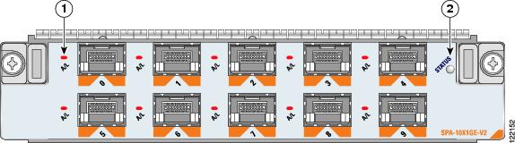
The 10-Port Gigabit Ethernet SPA has two types of LEDs: an A/L LED for each individual port and a STATUS LED for the SPA, as shown in the figure below:
|
1 |
A/L (Active/Link) LED |
2 |
STATUS LED |
The table below describes the 10-Port Gigabit Ethernet SPA LEDs.
|
LED Label |
Color |
State |
Meaning |
|---|---|---|---|
|
A/L |
Off |
Off |
Port is not enabled. |
|
|
Green |
On |
Port is enabled and the link is up. |
|
|
Amber |
On |
Port is enabled and the link is down. |
|
STATUS |
Off |
Off |
SPA power is off. |
|
|
Green |
On |
SPA is ready and operational. |
|
|
Amber |
On |
SPA power is on and good, and the SPA is being configured. |
10-Port Gigabit Ethernet SPA Cables and Connectors
The 10-Port Gigabit Ethernet SPA has ten electrical connectors that support SFP modules. Each port can send and receive traffic using cabling appropriate for the SFP module inserted.
SFP Module Connections
The small form-factor pluggable (SFP) module is an input/output (I/O) device that plugs into the Gigabit Ethernet optical slots on the 10-Port Gigabit Ethernet SPA, linking the port with a 1000BASE-X fiber-optic network.
Note | The 10-Port Gigabit Ethernet SPA accepts only the SFP modules listed as supported in this document. An SFP module check is run every time an SFP is inserted into the 10-Port Gigabit Ethernet SPA, and only SFP modules that pass this check can be used by the 10-Port Gigabit Ethernet SPA. SFP modules exist for technologies other than Gigabit Ethernet and for products other than the 10-Port Gigabit Ethernet SPA. However, the information in this document pertains only to SFP modules that plug into the 10-Port Gigabit Ethernet SPA ports. |
The SFP module has a receiver port (RX) and a transmitter port (TX) that compose one optical interface. The tables below provide SFP information and specifications.
|
SFP Module Product Number |
SFP Module |
Description |
|---|---|---|
|
SFP-GE-S |
Short wavelength (1000BASE-SX) |
Contains a Class 1 laser of 850 nm for 1000BASE-SX (short-wavelength) applications. |
|
SFP-GE-L |
Long wavelength/long haul (1000BASE-LX/LH) |
Contains a Class 1 laser of 1310 nm for 1000BASE-LX/LH (long-wavelength) applications. |
|
SFP-GE-Z |
Extended wavelength (1000BASE-ZX) |
Contains a Class 1 laser of 1550 nm for 1000BASE-ZX (extended-wavelength) applications. |
|
Specification |
Description |
|---|---|
|
Wavelength |
SFP-GE-S: 770 to 860 nm SFP-GE-L: 1270 to 1355 nm SFP-GE-Z: 1500 to 1580 nm |
|
Cabling distance (maximum) |
SFP-GE-S: 500 m on 50/125um MMF; 300 m on 62.5/125um MMFSFP-GE-L: 6.2 miles (10 km)SFP-GE-Z: 49.7 miles (80 km) |
|
Operating case temperature range |
SFP-GE-S: 23 to 185 degrees F (–5 to 85 degrees C) SFP-GE-L: 23 to 185 degrees F (–5 to 85 degrees C) SFP-GE-Z: 23 to 185 degrees F (–5 to 85 degrees C) |
|
Storage temperature range |
SFP-GE-S: –40 to 185 degrees F (–40 to 85 degrees C) SFP-GE-L: –40 to 185 degrees F (–40 to 85 degrees C) SFP-GE-Z: –40 to 185 degrees F (–40 to 85 degrees C) |
|
Supply voltage range |
SFP-GE-S: 3.1 to 3.5 V SFP-GE-L: 3.1 to 3.5 V SFP-GE-Z: 3.1 to 3.5 V |
SFP-GE-S Modules
The 1000BASE-SX (short-wavelength) module operates on standard multimode fiber-optic link spans of up to 500 m on 50/125um multimode fiber (MMF) and 300 m on 62.5/125um MMF.
SFP-GE-L Modules
The 1000BASE-LX/LH (long-wavelength/long-haul) module interfaces fully comply with theIEEE 802.3z 1000BASE-LX standard. However, their higher optical quality allows them to reach 6.2 miles (10 km) over single-mode fiber (SMF) versus the 3.1 miles (5 km) specified in the standard.
SFP-GE-Z Modules
The 1000BASE-ZX (extended-wavelength) module operates on ordinary single-mode fiber-optic link spans of up to 49.7 miles (80 km). Link spans of up to 62.1 miles (100 km) are possible using premium single-mode fiber or dispersion-shifted single-mode fiber. (Premium single-mode fiber has a lower attenuation per unit length than ordinary single-mode fiber; dispersion-shifted single-mode fiber has both lower attenuation and less dispersion.)
The 1000BASE-ZX module must be coupled to single-mode fiber-optic cable, which is the type of cable typically used in long-haul telecommunications applications. The 1000BASE-ZX module does not operate correctly when coupled to multimode fiber, and it is not intended to be used in environments in which multimode fiber is frequently used (for example, building backbones or horizontal cabling).
The 1000BASE-ZX module is intended to be used as a Physical Medium Dependent (PMD) component for Gigabit Ethernet interfaces found on various switch and router products. It operates at a signaling rate of 1250 Mbaud, transmitting and receiving 8B/10B encoded data.
When shorter lengths of single-mode fiber are used, it may be necessary to insert an inline optical attenuator in the link to avoid overloading the receiver. Use the following guidelines:
- Insert a 10-dB inline optical attenuator between the fiber-optic cable plant and the receiving port on the 1000BASE-ZX module at each end of the link whenever the fiber-optic cable span is less than 15.5 miles (25 km).
- Insert a 5-dB inline optical attenuator between the fiber-optic cable plant and the receiving port on the 1000BASE-ZX module at each end of the link whenever the fiber-optic cable span is equal to or greater than 15.5 miles (25 km) but less than 31 miles (50 km).
SFP Module Cabling and Connection Equipment
The table below provides cabling specifications for the SFP modules that can be installed on the 10-Port Gigabit Ethernet SPA. Note that all SFP ports have LC-type connectors.
The minimum cable distance for the SFP-GE-S is 6.5 feet (2 m), and the minimum link distance for the SFP-GE-Z is 6.2 miles (10 km) with an 8-dB attenuator installed at each end of the link. Without attenuators, the minimum link distance for the SFP-GE-Z is 24.9 miles (40 km).
|
SFP Modules |
Wavelength (nm) |
Fiber Type |
Core Size (micron) |
Modal Bandwidth (MHz/km) |
MaximumCable Distance |
|
|---|---|---|---|---|---|---|
|
SFP-GE-S |
850 |
MMF4 |
62.5 |
160 |
722 ft (220 m) |
|
|
|
62.5 |
200 |
984 ft (300 m) |
|||
|
|
50.0 |
400 |
1640 ft (500 m) |
|||
|
|
50.0 |
500 |
1804 ft (550 m) |
|||
|
SFP-GE-L |
1300 |
SMF |
9/10 |
— |
49.7 miles (80 km) |
|
|
SFP-GE-Z |
1500 |
SMF |
9/10 |
— |
49.7 miles (80 km) |
|
|
SMF
|
8 |
— |
62.1 miles (100 km) |
Note | The 1000BASE-ZX SFP modules provide an optical power budget of 21.5 dB. You should measure your cable plant with an optical loss test set to verify that the optical loss of the cable plant (including connectors and splices) is less than or equal to 21.5 dB. The optical loss measurement must be performed with a 1550-nm light source. |
1-Port 10-Gigabit Ethernet SPA Overview
The following sections describe the 1-Port 10-Gigabit Ethernet SPA:
- 1-Port 10-Gigabit Ethernet SPA LEDs
- 1-Port 10-Gigabit Ethernet SPA XFP Optical Transceiver Modules, Connectors, and Cables
1-Port 10-Gigabit Ethernet SPA LEDs
The 1-Port 10-Gigabit Ethernet SPA has two LEDs, an ACTIVE/LINK LED for the port and a STATUS LED, as shown in the figure below.
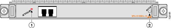
|
1 |
ACTIVE/LINK LED |
2 |
STATUS LED |
The table below describes the 1-Port 10-Gigabit Ethernet SPA LEDs.
|
LED Label |
Color |
State |
Meaning |
|---|---|---|---|
|
ACTIVE/LINK |
Off |
Off |
Port is not enabled by software. |
|
|
Green |
On |
Port is enabled by software and the link is up. |
|
|
Amber |
On |
Port is enabled by software and the link is down. |
|
STATUS |
Off |
Off |
SPA power is off. |
|
|
Green |
On |
SPA is ready and operational. |
|
|
Amber |
On |
SPA power is on and good, and the SPA is being configured. |
1-Port 10-Gigabit Ethernet SPA XFP Optical Transceiver Modules, Connectors, and Cables
The 1-Port 10-Gigabit Ethernet SPA supports the following types of optical transceiver modules:
- Single-mode short-reach (SR) XFP module—XFP-10GLR-OC192SR
- Single-mode intermediate-reach (IR) XFP module—XFP-10GER-OC192IR
- Single-mode very-long-reach (ZR) XFP module—XFP-10GER-OC192LR
- Multi-mode short reach (SR) XFP module—XFP-10G-MM-SR
Cisco Systems qualifies the optics that are approved for use with its SPAs. As of Cisco IOS XR Release 3.4.1, the above-listed small form-factor pluggable (XFPs) are the only optical transceiver modules qualified for use.
Use a single-mode optical fiber that has a modal-field diameter of 8.7 ±0.5 microns (nominal diameter is approximately 10/125 microns) to connect your router to a network.
The figure below shows the cable type for use with the XFP optical transceiver module on the 1-Port 10-Gigabit Ethernet SPA.
Note | The 40-pin connector on the 1-Port 10-Gigabit Ethernet SPA is used for resilient packet ring (RPR) connections. This feature is not supported inCisco IOS XR Release 3.4.1. |
XFP Connections
The 10GLR, 10GER, and 10GZR XFP modules include an optical transmitter and receiver pair integrated with Clock and Data Recovery (CDR) integrated circuits. The XFP modules provide high-speed serial links at the rate of 10.3125 Gbps (10 Gigabit Ethernet) on single-mode fiber (SMF). The transmit side recovers and retimes the 10-Gbps serial data and passes it to a laser driver. The laser driver biases and modulates a 1310-nm, 850 nm or 155-nm laser, enabling data transmission over SMF through an LC connector. The receive side recovers and retimes the 10-Gbps optical data stream from a photo detector transimpedance amplifier and passes it to an output driver.
See the label on the XFP module for technology type and model. The figure below shows an XFP module and the table below shows the XFP module specifications.
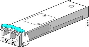
XFP module dimensions are:
|
Specification |
Description |
|---|---|
|
Wavelength (TX) |
10GLR SR-1: 1260 nm to 1355 nm 10GER IR-2: 1530 nm to 1565 nm 10GZR LR-2: 1530 nm to 1565 nm 10G-MM-SR: 840 nm to 860 nm |
|
Cabling distance (maximum) |
10GLR SR-1: 6.2 miles (10 km) 10GER IR-2: 24.8 miles (40 km) 10GZR LR-2: 50 miles (80 km) 10G-MM-SR: 26m, 33m, 66m, 82m, 300m |
|
Operating case temperature range |
10GLR SR-1: 23 to 158 degrees F (–5 to 70 degrees C) 10GER IR-2: 23 to 158 degrees F (–5 to 70 degrees C) 10GZR LR-2: 23 to 158 degrees F (–5 to 70 degrees C) 10G-MM-SR: 32 to 158 degrees F (0 to 70 degrees C) |
|
Storage temperature range |
10GLR SR-1: –40 to 185 degrees F (–40 to 85 degrees C) 10GER IR-2: –40 to 185 degrees F (–40 to 85 degrees C) 10GZR LR-2: –40 to 185 degrees F (–40 to 85 degrees C) 10G-MM-SR: –40 to 185 degrees F (–40 to 85 degrees C) |
|
TX power |
10GLR SR-1: –8.2 to 0.5 dBm 10GER IR-2: –4.7 to 4 dBm 10GZR LR-2: 0 to 4 dBm 10G-MM-SR: 3dBm,-1.5dBm,-1dBm |
|
Receiver sensitivity (maximum) |
10GLR SR-1: –12.6 dBm 10GER IR-2: –14.1 dBm 10GZR LR-2: –24 dBm 10G-MM-SR: -11.1dBm |
|
RX overload |
10GLR SR-1: 0.5 dBm 10GER IR-2: –1.0 dBm 10GZR LR-2: –7.0 dBm 10G-MM-SR: 1.0 dBm |
|
Maximum receiver power damage |
10GLR SR-1: +5 dBm 10GER IR-2: +5 dBm 10GZR LR-2: +5 dBm 10G-MM-SR: -1dBm |
XFP Port Cabling Specifications
The table below shows the port cabling specifications for an XFP module.
|
XFP Module |
Wavelength |
Fiber Type |
|---|---|---|
|
XFP-10GLR-OC192SR |
1310 nm |
SMF |
|
XFP-10GER-OC192IR |
1550 nm |
SMF |
|
XFP-10GZR-OC192LR |
1550 nm |
SMF |
|
XFP-10G-MM-SR |
850 nm |
MMF |
2-Port and 4-Port Clear Channel T3/E3 SPA Overview
The following sections describe the 2-Port and 4-Port Clear Channel T3/E3 SPA:
- 2-Port and 4-Port Clear Channel T3/E3 SPA LEDs
- 2-Port and 4-Port Clear Channel T3/E3 SPA Interface Specifications
- 2-Port and 4-Port Clear Channel T3/E3 SPA Cables and Connectors
2-Port and 4-Port Clear Channel T3/E3 SPA LEDs
The 2-Port and 4-Port Clear Channel T3/E3 SPA has three types of LEDs: two LEDs for each port on the SPA, and one STATUS LED, as shown in the figure below.
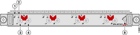
|
1 |
C/A (Carrier/Alarm) LED |
4 |
RX (Receive) connector |
|
2 |
A/L (Active Loopback) LED |
5 |
STATUS LED |
|
3 |
TX (Transmit) connector |
|
|
The table below describes the 2-Port and 4-Port Clear Channel T3/E3 SPA LEDs.
|
LED Label |
Color |
State |
Meaning |
|---|---|---|---|
|
C/A |
Off |
Off |
Port is not enabled by software. |
|
|
Green |
On |
Port is enabled by software, and there is a valid E3 or T3 signal without any alarms. |
|
|
Amber |
On |
Port is enabled by software, and there is at least one alarm. |
|
A/L |
Off |
Off |
Port is not enabled by software. |
|
|
Green |
On |
Port is enabled by software, and loopback is off. |
|
|
Amber |
On |
Port is enabled by software, and loopback is on. |
|
STATUS |
Off |
Off |
SPA power is off. |
|
|
Green |
On |
SPA is ready and operational. |
|
|
Amber |
On |
SPA power is on and good, and the SPA is being configured. |
2-Port and 4-Port Clear Channel T3/E3 SPA Interface Specifications
The framer processes incoming and outgoing T3 (cbit, m13/m23, and unframe) and E3 (g751, g832, and unframe) frames. The framer operates at T3/E3 line rates (44.736 /34.368 Mbps) depending on the mode in which it is configured.
Packet data is transported with a user-configurable encapsulation (such as Point-to-Point Protocol [PPP] or High-Level Data Link Control [HDLC]), and is mapped to T3 and E3 frames. The encapsulations add transport overhead to the packet of data frames before transporting, and are stripped when a packet is transported to the far end.
The T3/E3 SPA interface is compliant with ANSI and Telco standards. The interface also provides support for Management Information Base (MIB) RFC 2496 and T1.231.
2-Port and 4-Port Clear Channel T3/E3 SPA Cables and Connectors
The interface connectors on the 2-Port and 4-Port Clear Channel T3/E3 SPA are 75-ohm coaxial Siemax types, with one connector and cable for transmit (TX) and one for receive (RX).
The following cables can be used with the 2-Port and 4-Port Clear Channel T3/E3 SPA. The cables have BNC connectors on one end and the Siemax connectors on the other. If similar SPAs are connected back-to-back, both ends of cable will be Siemax.
- CAB-T3E3-RF-BNC-M (T3 or E3 Cable, 1.0/2.3 RF to BNC-Male, 10 feet)
- CAB-T3E3-RF-BNC-F (T3 or E3 Cable, 1.0/2.3 RF to BNC-Female, 10 feet)
- CAB-T3E3-RF-OPEN (T3 or E3 Cable, 1.0/2.3 RF to BNC-Open end, 10 feet)
Note | The Cisco cable part numbers are 72-4124-01 (with male BNC end) and 72-4131-01 (with female BNC end). |
SFP Module Connections shows the connectors on the 4-Port Clear Channel T3/E3 SPA, and the table below describes the signal descriptions for these connectors.
|
Connector Label |
Meaning |
|---|---|
|
TX |
Transmitted signals appear on the center contact, and the outer shield is ground for the 75-ohm RG-59 coaxial cable you attach to the TX BNC connector. |
|
RX |
Received signals appear on the center contact, and the outer shield is ground for the 75-ohm RG-59 coaxial cable you attach to the RX BNC connector. |
 Feedback