Fabric Card Chassis Cooling System
This chapter describes the components that make up the cooling system of the fabric card chassis (FCC). It includes these sections:
Cooling System Overview
The FCC cooling system dissipates the heat generated by the routing system and controls the temperature of components in the FCC. The cooling system has a fully-redundant architecture that allows the routing system to continue operating with a single-fault failure (such as a single fan or fan tray failure). The architecture also supports a redundant load-sharing design.
The complete FCC cooling system includes:
- Two fan trays (each holds nine fans)
- Temperature sensors (on cards and modules throughout the FCC)
- Control software and logic
- An air filter, inlet and outlet air vents, and bezels
- Impedance carriers for empty FCC slots
The power modules in the power shelves also have their own self-contained cooling fans.
All nine fans in a fan tray operate as a group. So, if it is necessary to increase or decrease airflow, all fans in the tray increase or decrease their rotation speed together. When two fan trays are operational in an FCC, the speed of the fans in both trays is adjusted together.
Thermal sensors (inlet, exhaust, and hot-spot) located throughout the FCC are used to monitor temperature readings and identify when the system is not cooling properly. Software running on the SCGE (2-port or 22-port) card is used to control the operation of the fans.
FCC Airflow
The airflow through the FCC is controlled by a push-pull configuration. The bottom fan tray pulls in ambient air from the bottom front of the chassis, and the top fan pulls the air up through the card cages and exhausts warm air from the top rear of the FCC.

|
1 |
Front of chassis |
7 |
Air exhaust |
|
2 |
Room air |
8 |
Upper card cage |
|
3 |
Bottom fan tray |
9 |
OIM side of chassis |
|
4 |
SFC side of chassis |
10 |
Lower card cage |
|
5 |
Top fan tray |
11 |
Air filter |
|
6 |
Power shelves |
12 |
Rear of chassis |
 Note | The FCC has a maximum airflow of 2050 cubic feet per minute. |
The FCC has a replaceable air filter mounted in a slide-out tray above the lower fan tray. The FCC air filter, shown in the below figure, plugs into the front (SFC) side of the FCC.
You should change the air filter as often as necessary. In a dirty environment, or when you start getting frequent temperature alarms, check the intake grills for debris and check the air filter to see if it needs to be replaced. Before removing the air filter for replacement, you should have a spare filter on hand. Then, when you remove the dirty filter, install the spare filter in the FCC.
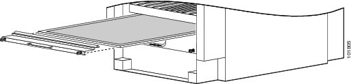
Note | A lattice of wire exists on both sides of the air filter with an arrow that denotes airflow direction, and a pair of sheet metal straps on the downstream side of the filter assembly. |
Cooling System Operation
The fan control software and related circuitry varies the DC input voltage to individual fans to control their speeds. The software and circuitry increase or decrease the airflow needed to keep the routing system operating at a desired temperature range. The FCC cooling system uses multiple fan speeds to optimize cooling, acoustics, and power consumption. Four fan speeds are used for normal operation and one high-speed setting is used when a fan tray has failed.
At initial power up, the routing system control software powers on the fans to a range of 4300 to 4500 RPM. This control software provides airflow during system initialization and software boot and ensures that adequate cooling exists for the system, if the software hangs during boot. The fan control software is initialized after the routing system software boots, which can take from 3 to 5 minutes. The fan control software then adjusts the fan speeds appropriately.
During normal operation, the system averages the temperatures reported by inlet temperature sensors in the lower card cage (or in the upper card cage, if the lower cage is empty). To determine the appropriate fan speed for the current temperature, the fan control software compares the average inlet temperature to a lookup table that lists the optimal fan speed for each temperature. The software then sets the fan speed to the appropriate value for the current temperature. The temperature ranges in the lookup table overlap to ensure a proper margin to avoid any type of fan speed oscillation occurring between states.
Note | When no active alarms or failures exist, the fan control software checks temperature sensors every 1 to 2 minutes. |
Thermal Alarms
Local thermal sensors (on individual cards) monitor temperatures and generate a thermal alarm when the system is not cooling properly. A temperature sensor might trip in response to an elevated ambient air temperature, a clogged air filter or other airflow blockage, or a combination of these conditions. A fan failure causes a fault message, but if no thermal sensors have tripped, the fan control remains unchanged.
When a thermal sensor reports a thermal alarm, the sensor passes the fault condition to its local service processor (SP), which then notifies the SCGE (2-port or 22-port) card. The fan control software on the SCGE (2-port or 22-port) card then takes appropriate action to resolve the fault.
When a thermal sensor trips, the fan control software tries to resolve the problem (for example, by increasing fan speed). The software performs a series of steps to prevent FCC components from getting anywhere near reliability-reducing, chip-destroying temperatures. If the fault continues, the software shuts down the card or module, to save components.
Quick-Shutdown Mode
The fan trays have a quick-shutdown mode that turns off power when a card or fan tray is disengaged from the FCC backplane. The quick-shutdown mode minimizes inrush current during a hot swap or OIR. In normal maintenance conditions, the software gracefully turns off power to the failed part, allowing ample time for capacitors to discharge.
Fan Controller Redundancy in the FCC
This section describes the redundant architecture of the cooling system, which allows the cooling system to continue operating even when certain components have failed.
The SCGE (2-port or 22-port) cards provide fully redundant input power and control logic for fan trays and fans. Each SCGE card receives its input power (-48 VDC) from both the A and B power shelves. The SCGE card then provides one fan tray with input power from the A bus and provides power to the other fan tray from the B bus. This provision ensures that the upper fan tray is powered from the A bus on one SCGE card and from the B bus on the second SCGE card.
In a fully redundant system that is equipped with dual power feeds, dual SCGE cards, and dual fan trays-the cooling system can withstand the failure of any one of these components and still continue to properly cool the chassis:
- Fan tray — If one fan tray fails or is removed, the other fan tray automatically speeds up to the maximum limit and provides cooling for the entire chassis. (If multiple fans in a single fan tray fail, the remaining fans in the two fan trays provide cooling for the entire chassis.)
- SCGE card — If one SCGE card fails, the other SCGE card provides all of the power to the fan trays.
- Power shelf or power module (DC PEM or AC rectifier) — If one power feed fails, the other power feed provides all of the power to the fan trays
In the single-failure cases described in this section, the rotational speed of the remaining operational fans changes automatically according to the cooling needs of the chassis.
A double-fault fan failure involves two fan trays, two fan tray boards, two SCGE cards, two power shelves, two power modules (DC PEMs or AC rectifiers), or any combination of two of these components. When a double-fault failure occurs, the system can automatically power down individual cards if the cooling power is insufficient to maintain them. The chassis remains powered on, unless both fan trays have failed, or thermal alarms indicate a problem serious enough to power down the entire chassis.
Note | When a cooling system component fails, it should be replaced within 24 hours, or sooner. |
The SCGE (2-port or 22-port) cards provide fully-redundant input power and control logic for fan trays and fans. Each SCGE (2-port or 22-port) card receives its input power (–48 VDC) from both the A and B power shelves. The SCGE (2-port or 22-port) card then provides one fan tray with input power from its A bus and provides power to the other fan tray from its B bus. This provision ensures that the upper fan tray is powered from the A bus on one SCGE (2-port or 22-port) card and from the B bus on the second SCGE (2-port or 22-port) card.
For information on the rotational speeds of the fans in revolutions per minute (RPM), see the FCC Fan Tray section.
FCC Fan Tray
This figure shows a fan tray, which plugs into the front (SFC) side of the FCC. Each fan tray is hot swappable and is considered a field-replaceable unit. The FCC is designed to run with both fan trays in place.
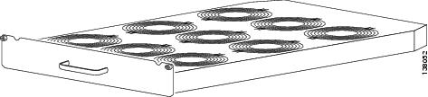
Each fan tray contains:
- Nine fans — The FCC fans are powered up with regulated –54 VDC for the AC system. For the DC system, the fans receive the input voltage that is applied to the DC PEM modules. This input ranges from –42 VDC to –72 VDC.
- Fan tray board — The board terminates signals to and from the fans, filters common-mode noise, and contains tracking and indicator parts.
-
Front-panel status LED — The LED indicates:
- Green—The fan tray is operating normally.
- Yellow—The fan tray has failed and should be replaced.
- Off—An unknown state exists or the LED is faulty.
During normal operation, the fans operate in the range of 3500 to 5150 RPM. The system automatically adjusts the speed of the fans to meet the cooling needs of the entire chassis. If one SCGE card or one power feed fails, the fans continue to operate within the range specified above (up to 5150 RPM). If one fan tray fails completely, or is removed, the fans in the remaining fan tray automatically speed up to the maximum rotational limit, which is 6600 RPM.
Note | The fan speed range limits listed in this document are nominal. These numbers have a tolerance of plus or minus 10 percent. |
The fan tray has these physical characteristics:
- Overall depth—30.9 inches (78.5 cm)
- Height of tray body—2.5 inches (6.2 cm)
- Height of front panel—4 inches (10.2 cm)
- Depth of front panel—1 inches (2.5 cm)
- Weight—44 pounds (20 kg)
 Feedback