Overview
 Note | You must plan the site before the scheduled delivery of the system because installation of a CRS 8-slot LCC may require space, floor loading, power, and cooling modifications to a facility. |
Cisco CRS Carrier Routing System 8-Slot Line Card Chassis Overview
Carrier Routing System (CRS) replaces much of the equipment in service provider points of presence (POPs) today. The routing systems are built around a scalable, distributed three-stage switch fabric and a variety of line card (packet) interfaces. These packet interfaces are located on modular services cards (MSCs) or forwarding processors (FP) and their associated physical layer interface modules (PLIMs), which are effectively cross-connected to each other through the switch fabric.
CRS 8-slot LCC is a half-height, rack-mounted 8-slot version of the 16-slot chassis. It is a highly scalable routing system that provides 6.4 terabits per second (Tbps) of routing capacity and supports up to 8 MSCs or FPs (A terabit is 1 x 1012 bits or 1,000 Gigabits). The chassis installs in a 19-inch equipment rack.
CRS 8-slot LCC can be installed in collocation facilities, data centers, and many Tier II and Tier III locations. The routing system consists of a single rack-mounted chassis that contains the following system components:
- Modular services cards (MSCs) or forwarding processors (FP), also called line cards (up to eight).
- Physical layer interface modules, or PLIMs (up to eight, one for each MSC or FP).
- Route processor (RP) cards (up to two) or performance route processor (PRP) cards (up to two).
- Switch fabric cards (SFCs) (four required).
- A chassis mid-plane that connects MSCs or FPs to their PLIMs and to switch fabric cards.
CRS 8-slot LCC has its own power and cooling sub-systems. Two types of power systems are available: fixed or modular configuration. Both power configurations use either AC or DC power.
CRS 8-slot LCC supports 40G, 140G, and 200G fabric cards, as follows:
- Cisco CRS-1 Carrier Routing System uses fabric cards designed for 40 G operation (CRS-8-FC/S or CRS-8-FC/M cards).
- Cisco CRS-3 Carrier Routing System uses fabric cards designed for 140G operation (CRS-8-FC140/S or CRS-8-FC140/M cards).
- Cisco CRS-X Carrier Routing System uses fabric cards designed for 200G operation (CRS-8-FC400/S cards in 200G mode).
A mixture of 40G, 140G, and 200G fabric cards is not supported except during migration.
Note | Throughout this document, the term Cisco CRS Carrier Routing system refers to Cisco CRS-1, Cisco CRS-3, and Cisco CRS-X Carrier Routing Systems, unless otherwise specified. |
Cisco CRS 8-Slot Line Card Chassis
Cisco CRS 8-slot LCC is the main component of Cisco CRS. The chassis is a mechanical enclosure that contains a chassis mid-plane. The mid-plane holds the system Modular Services Cards (MSCs), Forwarding Processor (FP) cards, their associated Physical Layer Interface Modules (PLIM), and Switch Fabric Cards (SFCs). Cisco CRS 8-slot LCC contains its own power system; either fixed or modular configuration (see Chassis Power System). The chassis is mounted on a 19-inch equipment rack (see Equipment Rack Considerations).
This section describes the main components of Cisco CRS 8-slot LCC that are considered Field-Replaceable Units (FRUs), but where additional detail is useful, the section identifies sub-assemblies that are not field-replaceable.
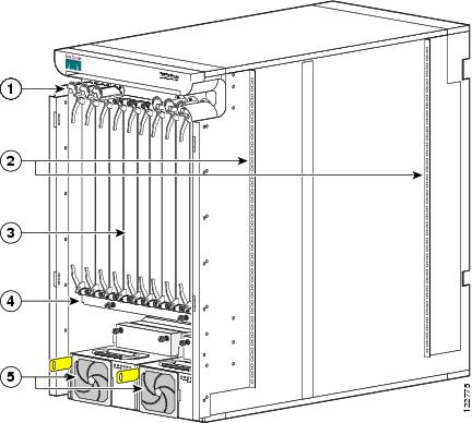
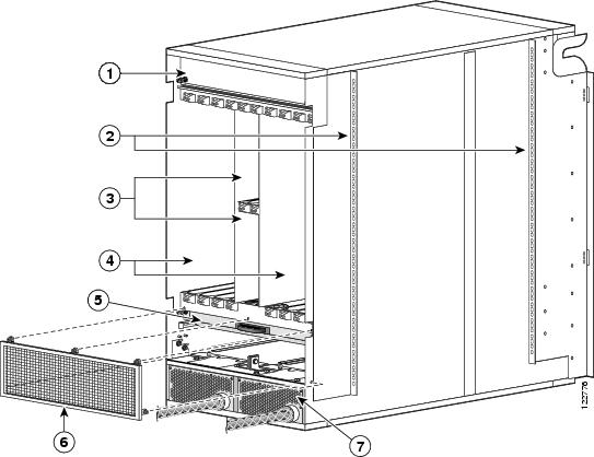
The following figure shows the front view of Cisco CRS 8-slot LCC with a fixed configuration AC power system installed. The front view of a Cisco CRS 8-slot LCC with a fixed configuration DC power system installed is similar to this figure.
|
1 |
Cable management bracket |
4 |
Air filter |
|
2 |
Chassis vertical mounting brackets |
5 |
Power system |
|
3 |
PLIM and RP slots (RPs in middle 2 slots) |
|
|
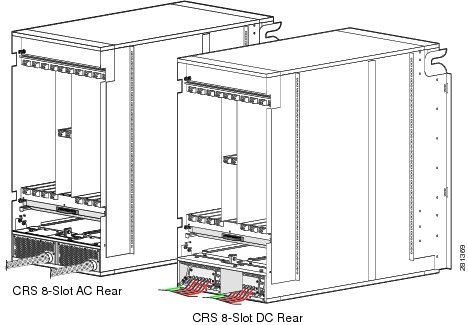
The following figure shows the rear view of a Cisco CRS 8-slot LCC with an AC and a DC fixed configuration power supply installed.
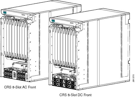
The following figure shows the front view of a Cisco CRS 8-slot LCC with an AC and a DC modular configuration power supply installed.
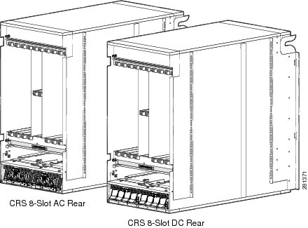
The following figure shows the rear view of a Cisco CRS 8-slot LCC with an AC and a DC modular configuration power supply installed.
The following figure shows the rear view of a Cisco CRS 8-slot line card chassis with a fixed configuration AC power system installed.
|
1 |
Upper fan tray (beneath cover) |
5 |
Lower fan tray |
|
2 |
Chassis vertical mounting brackets |
6 |
Cooling air outlet screen |
|
3 |
Switch fabric card (half-height) slots |
7 |
Power distribution units (PDUs) |
|
4 |
MSC slots |
|
|
Chassis Components
Cisco CRS 8-slot LCC contains the following components:
- As many as eight modular services cards (MSCs) or forwarding processor (FP) cards (both types are also called line cards), and eight physical layer interface modules (PLIMs). The MSC or FP and PLIM are an associated pair of cards that mate through the chassis mid-plane. The MSC or FP provides the forwarding engine for Layer 3 routing of user data, and the PLIM provides the physical interface and connectors for the user data.
Each MSC or FP can be associated with several different PLIMs, which provide different interface speeds and technologies. Some of the available PLIMs are:
Note | For a complete list of available PLIMs, consult your Cisco sales representative or visit http://www.cisco.com. |
-
- 1-port OC-768c/STM-256c packet-over-SONET (POS). Available with short-reach (SR) optics.
- 4-port OC-192c/STM-64c POS/DPT. Available with long-reach (LR), intermediate-reach (IR), short-reach (SR), and very-short-reach (VSR) optics.
- OC-48c/STM-16c POS/DPT, configurable with 1 to 16 ports. Available with long-reach (LR) and short-reach (SR) optics. This PLIM supports pluggable optics.
- 10-Gigabit Ethernet PLIMs (available with a variety of optics, including LR). These PLIMs support pluggable XENPAK and XFP optics, and can be configured with up to 20 ports, depending on the PLIM.
- 100-Gigabit Ethernet PLIM. This single-port PLIM supports a pluggable CFP optics module.
- Cisco CRS SPA Interface Processor-800. Occupies one PLIM slot on the Cisco CRS 16- and 8-Slot LCC. Supports six normal-height SPAs or three double-height SPAs or any combination in between.
- Chassis mid-plane. The mid-plane connects MSCs to their associated PLIMs and allows an MSC to be removed from the chassis without having to disconnect the cables that are attached to the associated PLIM. The midplane distributes power, connects the MSCs to the switch fabric cards, and provides control plane interconnections. The midplane is not field replaceable by the customer.
- One or two route processor cards (RPs). The RPs provide the intelligence of the system by functioning as the LCC system controller and providing route processing. Only one RP is required for system operation. For redundant operation, you can order a second, redundant RP as an option (CRS-8-RP/R). When two RPs are used, only one RP is active at a time. The second RP acts as a “standby” RP, serving as a backup if the active RP fails.
The RP also monitors system alarms and controls the system fans. LEDS on the front panel indicate active alarm conditions.
A Performance Route Processor (PRP) is also available for the Cisco CRS 8-slot line card chassis. Two PRPs perform the same functions as two RPs, but provide enhanced performance for both route processing and system controller functionality.
Note | A chassis may not be populated with a mix of RP and PRP cards. Both route processor cards should be of the same type (RP or PRP). |
- Upper and lower fan trays. The fans pull cool air through the chassis. A removable air filter is located below the PLIM card cage at the front of the chassis. Each fan tray contains four fans.
- Four half-height switch fabric cards (SFCs). These cards provide the three-stage Benes switch fabric (S1/S2/S3) for the routing system. The switch fabric performs the cross-connect function of the routing system, connecting every MSC (and its associated PLIM) with every other MSC (and its associated PLIM) in the system.
The switch fabric receives user data from one MSC (or FP) and PLIM pair and performs the switching necessary to route the data to the appropriate egress MSC (or FP) and PLIM pair. The switch fabric is divided into eight planes that evenly distribute the traffic across the switch fabric. Each switch fabric card implements two planes of the switch fabric.
- A power system that provides redundant power to the chassis. Two types of power systems are available: fixed configuration power and modular configuration power. Both power configurations use either AC or DC power. The fixed configuration power solution contains two power distribution units (PDUs), with either one AC rectifier or one DC power entry modules (PEM) per PDU. Each DC PEM and AC rectifier contains a removable air filter, located on the back of the module. The modular configuration power solution contains two power shelves with either up to four DC power modules (PMs) or up to three AC PMs per power shelf.
The PLIM side of the chassis is considered the front of the chassis, where user data cables attach to the PLIMs and cool air enters the chassis. The MSC side, which is where warm air is exhausted, is considered the rear of the chassis.
Chassis Slot Numbers
This section identifies the location and slot numbers for major cards and modules (primarily the field-replaceable units) that plug into the chassis.
The following figure shows the slot numbers on the front (PLIM) side of the Cisco CRS 8-slot line card chassis.
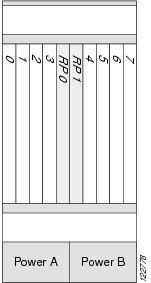
As shown, the front (PLIM) side of the chassis has the following card slots:
- Eight PLIM slots (left to right: 0, 1, 2, 3...4, 5, 6, 7)
- Two route processor card slots (RP0 and RP1)
The following figure shows the slot numbers on the rear (MSC) of the chassis.
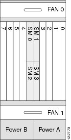
The rear (MSC) side of the chassis has the following card slots:
- Eight MSC slots (left to right: 7, 6, 5, 4...3, 2, 1, 0)
- Four half-height switch fabric card slots (SM0, SM1, SM2, and SM3)
The MSC slot numbers are reversed from the PLIM slot numbers on the other side of the chassis. Because an MSC mates with its associated PLIM through the midplane, MSC slot 0 is on the far right side of the chassis looking at it from the rear (MSC) side.
PLIM slot 0 is on the far left side of the chassis, looking at if from the front (PLIM) side. MSC slot 0 and PLIM slot 0 mate with each other through the midplane, and so do all other MSC and PLIM slots (0 through 7).
Overview of Site Planning Steps
The table lists the sequence of tasks to perform as you plan the installation of the routing system. Use the table as a checklist for all aspects of the installation. For information about a particular task, see the appropriate section of this site planning guide. After completing the checklist, you should consult your Cisco installation coordinator for a site-readiness inspection.
|
Site Planning Steps |
See |
Check |
|---|---|---|
|
Determine where to install the routing system and make sure that you have the appropriate installation and configuration tools. |
|
|
|
Consider equipment arrival, storage, and transport to the installation site. |
|
|
|
Make sure that the equipment rack meets the installation requirements. |
|
|
|
Consider the space where the routing system will be installed. |
|
|
|
Plan for power (fixed or modular configuration power, AC or DC). |
|
|
|
Consider cooling and airflow requirements. |
|
|
|
Consider cable management. |
|
|
|
Consider Cisco installation services. |
|
 Feedback