Bring-up the Cisco 8000 Series Router

Connect to the console port on a Route Processor (RP) of the router, and power ON the router. By default, this console port connects to the XR console. If necessary, after configuration, establish subsequent connections through the management port.

The following table shows the console settings:

Table 1. Console Settings

Baud rate (in bps)

Parity

Stop bits

Data bits

115200

None

2

8

The baud rate is set by default and cannot be changed.

The router can be accessed using remote management protocols, such as SSH, Telnet, SCP and FTP. SSH is included in the software image by default, but telnet is not part of the software image. You must manually install the telnet optional package to use it.

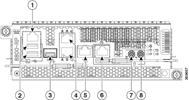
Figure 1. Ports of the Route Processor

1

Console RS-232 Serial Port RJ45

5

SyncE BITS/DTI/J.211

2

USB Port Type-A (2 ports). Port A gets detected ahead of Port B

Top: Port B

Bottom: Port A

6

G.703 Time-of-Day (TOD)

3

Control Plane Expansion SFP/SFP+ port

7

Mini coaxial connector for 10 MHz, input, and output

4

Top: Management Ethernet (10/100/1000-Mbps) RJ-45 (Copper) port LAN shared between x86 (XR) and ARM11

Bottom: IEEE 1588 Precision Time Protocol (PTP)

8

Mini coaxial connector for 1 PPS, input, and output

After booting is complete, you must create a username and password. This credential is used to log on to the XR console, and get to the router prompt.

You can start or stop the console by using the following keyboard shortcuts:

  • To start the console, press Ctrl + q.

  • To stop the console, press Ctrl + s.

Note that by using Ctrl + s, the console output will be locked and you will need to initiate a Ctrl + q sequence to restore the console prompt.

The router completes the boot process using the pre-installed operating system (OS) image. If no image is available within the router, the router can be booted using iPXE boot or an external bootable USB drive.

Get to Know Cisco 8000 Series Routers

Cisco 8000 series routers converge the service provider routing and massively scalable data centers (MSDC) switching portfolio. The routers run on XR 7 OS. The XR 7 OS provides significant architectural enhancements to Cisco IOS XR in these areas:

  • Modularity: Decoupled hardware and software; modularized software with the flexibility to consume software packages based on requirement.

  • Programmability: Model-driven APIs at all layers.

  • Manageability: Simplified software management and installation based on Linux tools.

Table 2. Feature History Table

Feature

Release Information

Feature Description

BaseboardManagement Controller (BMC)

Release 7.5.2

This feature is no longer supported.

Boot the Cisco 8000 Series Router Using Manual iPXE

Manually boot the router using iPXE if the router fails to boot when powered ON. An alternate method is to Boot from a USB device.

iPXE is a pre-boot execution environment in the network card of the management interfaces. It works at the system firmware (UEFI) level of the router. iPXE boot re-images the system, boots the router in case of a boot failure, or in the absence of a valid bootable partition. iPXE downloads the ISO image, installs the image, and finally bootstraps inside the new installation.

iPXE acts as a bootloader. It provides the flexibility to choose the image that the system boots. The image is based on the Platform Identifier (PID), the serial number, or the management mac-address. iPXE is defined in the DHCP server configuration file.

You need a server running HTTPS, HTTP, or TFTP. Bring-up the PXE prompt using the following steps:

When you bring up a router using the PXE boot mode, existing configurations are removed. To recover smart licensing configurations like Permanent License Reservation (PLR), enable these configurations after the router comes up.

Router# configure
Router(config)# license smart reservation
Router(config)# commit

Procedure


Step 1

Power ON the router.

Step 2

Press Esc or Del keys continuously (quick and repeated press and release) to pause the boot process, and get to the BIOS menu.

Step 3

Select Boot Manager, and then select Built-in iPXE option.

Step 4

When PXE boot starts reaching for a PXE server, press Ctrl+B keys to break into the PXE prompt.

Step 5

Add the following configuration for the router. This is required for the router to connect with the external server to download, and install the image. You can use HTTP, HTTPS or TFTP server.

Example:


iPXE> ifopen net0                    #Open the interface connecting outside world
iPXE> set net0/ip 10.0.0.2           #Configure the ip address of your router                                                        
iPXE> set net0/gateway 10.0.0.1      #configure the GW
iPXE> set net0/netmask 255.0.0.0     #Configure the Netmask
iPXE> ping 10.0.0.1                  #Check you can reach GW
iPXE> ping 192.0.2.0                 #check you can reach to your server running tftp or http or https
iPXE> boot http://192.0.2.0/<directory-path>8000-x64.iso    #Copy the image on the http/https/tftp server in any path and then point to download the image from there. 

Note


To rectify errors while typing the command, use Ctrl+H keys to delete a character.

If a PXE server is configured to run a DHCP server, it assigns an IP address to the Ethernet Management interface of the router. This provides a channel to download the image that is required to re-image a router in case of a boot failure.

Router#reload bootmedia network location all
Proceed with reload? [confirm]

Note


Use the force option to perform an ungraceful reload of the specified location or hardware module. When force option is used along with the all location, the chassis undergoes an ungraceful reload. Use the noprompt option to avoid the prompt to confirm the operation. The force option is not recommended, and should not be used during regular operations.


Boot the Cisco 8000 Series Router Using USB Drive

Boot the router using USB drive if the router fails to boot when powered ON. An alternate method is to boot the router using iPXE.

Before you begin

Have access to a USB drive with a storage capacity that is between 8GB (min) and 32 GB (max). USB 2.0 and USB 3.0 are supported.


Note


Use this procedure only on the active RP; the standby RP must either be powered OFF or removed from the chassis. After the active RP is installed with images from the USB drive, insert or power ON the standby RP as appropriate.


Procedure


Step 1

Copy the bootable file to a USB disk.

A bootable USB drive is created by copying a compressed boot file into a USB drive. The USB drive becomes bootable after the contents of the compressed file are extracted.

Note


If you are unable to boot from a USB drive, remove and insert the drive again. If the drive is inserted correctly, and still fails to read from the USB drive, check the contents of the USB on another system.

This task can be completed using Windows, Linux, or MAC operating systems available on your local machine.

  1. Connect the USB drive to your local machine and format it with FAT32 or MS-DOS file system using the Windows Operating System or Apple MAC Disk Utility. To check if the disk is formatted as FAT32, right click on the USB disk, and view the properties.

  2. Copy the compressed boot file in .zip format from the image file to the USB drive. This .zip file can be downloaded from the Cisco Software Download center.

  3. Verify that the copy operation is successful. To verify, compare the file size at source and destination. Additionally, verify the MD5 checksum value.

  4. Extract the contents of the compressed boot file by unzipping it inside the USB drive. This converts the USB drive to a bootable drive.

    Note

     
    Extract the contents of the zipped file ("EFI" and "boot" directories) directly into the root folder of the USB drive. If the unzipping application places the extracted files in a new folder, move the "EFI" and "boot" directories to the root folder of the USB drive.
  5. Eject the USB drive from your local machine.

Step 2

Use the bootable USB drive to boot the router or upgrade its image using one of the following methods:

Note

 
Insert the USB drive in the USB port of the ACTIVE RP.
  • Boot menu
    1. Insert the USB drive, and connect to the console.

    2. Power ON the router.

    3. Press Esc or Del to pause the boot process, and get the RP to the BIOS menu.

    4. Select Boot Manager, and then select the USB option from the boot menu.

      Cisco BIOS Setup Utility - Copyright (C) 2019 Cisco Systems, Inc
      
      Boot Override
      UEFI: Micron_M600_MTFDDAT064MBF, Partition 4
      UEFI: Built-in iPXE
      URFI: Built-in Shell
      URFI: Built-in Grub
      UEFI: USB Flash Memory1.00, Partition 1

      The system boots the image from the USB drive, and installs the image onto the hard disk. The router boots from the hard disk after installation.

  • XR CLI

    Use this method if you can access the XR prompt.

    Note


    The RP has two USB ports. If there is only one USB drive with a bootable image, insert it into any of the two USB ports. If there are two USB drives but only one has a bootable image, the choice of the USB port is negligent. However, if two USB drives are inserted simultaneously and both have a bootable image, the image in the lower USB port takes precedence.

    1. Insert the USB device in the RP.

    2. Access the XR prompt and run the command:
      Router#reload bootmedia usb noprompt
      
      Welcome to GRUB!!
      Verifying (hd0,msdos1)/EFI/BOOT/grub.cfg...
      (hd0,msdos1)/EFI/BOOT/grub.cfg verified using Pkcs7 signature.
      Loading Kernel..
      Verifying (loop)/boot/bzImage...
      (loop)/boot/bzImage verified using attached signature.
      Loading initrd..
      Verifying (loop)/boot/initrd.img

      Use the force option to perform an ungraceful reload of the specified location or hardware module. When force option is used along with the all location, the chassis undergoes an ungraceful reload. Use the noprompt option to avoid the prompt to confirm the operation. The force option is not recommended, and should not be used during regular operations.

      The system boots the image from the USB and installs the image onto the hard disk. The router boots from the hard disk after installation.

    Note


    Execute the install commit command before proceeding to the next install iteration, while performing cyclic upgrade and downgrade tests.


Configure the Management Port on the Cisco 8000 Series Router

To use the management port for system management and remote communication, you must configure an IP address and a subnet mask for the Management Ethernet interface.


Note


We recommend that you use a Virtual Private Network (VPN) routing and the forwarding (VRF) on the Management Ethernet interface.


Before you begin

  • Consult your network administrator or system planner to procure IP addresses and a subnet mask for the management interface.

  • Physical port Ethernet 0 on RP is the management port. Ensure that the port is connected to the management network.

Procedure


Step 1

Configure a VRF.

Example:

Router#conf t
Router(config)#vrf <vrf-name>
Router(config-vrf)#exit

Step 2

Enter interface configuration mode for the management interface of the RP.

Example:

Router(config)#interface mgmtEth 0/RP0/CPU0/0

Step 3

Assign an IP address and a subnet mask to the interface.

Example:

Router(config-if)#ipv4 address 10.10.10.1/8

Step 4

Configure the Management Ethernet interface under the VRF.

Example:

Router(config-if)#vrf <vrf-name>

Step 5

Exit the management interface configuration mode.

Example:

Router(config-if)#exit

Step 6

Assign a virtual IP address and a subnet mask to the interface. The virtual address is primarily used for out-of-band management over the Management Ethernet interface.

Example:

Router(config)#ipv4 virtual address vrf <vrf-name> 10.10.10.1/8

Step 7

Place the interface in UP state.

Example:

Router(config)#no shutdown

Step 8

Specify the IP address of the default-gateway to configure a static route; this is used for communications with devices on other networks.

Example:

Router(config)#router static vrf <vrf-name> address-family ipv4 unicast 0.0.0.0/0 10.10.10.1

Step 9

Commit the configuration.

Example:

Router(config)#commit

Step 10

Connect to the management port to the ethernet network. With a terminal emulation program, establish a SSH or telnet connection to the management interface port using its IP address.


Synchronize Router Clock with NTP Server

Synchronize the XR clock with that of an NTP server to avoid a deviation from true time.

NTP uses the concept of a stratum to describe how many NTP hops away a machine is from an authoritative time source. A stratum 1 time server typically has an authoritative time source (such as a radio or atomic clock, or a GPS time source) directly attached to the server. A stratum 2 time server receives its time through NTP from a stratum 1 time server, and so on.

Note


The Cisco implementation of NTP does not support stratum 1 service.


Before you begin

Configure and connect to the management port.

Procedure


Step 1

Enter the XR configuration mode.

Example:

Router#configure

Step 2

Synchronize the console clock with the specified sever.

Example:

Router(config)#ntp server <NTP-source-IP-address>

The NTP source IP address can either be an IPv4 or an IPv6 address. For example:

IPv4:
Router(config)#ntp server 192.0.2.0
IPv6:
Router(config)#ntp server 2001:DB8::1

Note


The NTP server can also be reachable through a VRF if the Management Ethernet interface is in a VRF.

Step 3

Commit the configuration.

Example:

Router(config-ntp)#commit

Step 4

Verify that the clock is synchronised with the NTP server.

Example:

Router#show ntp status 
Clock is synchronized, stratum 3, reference is 192.0.2.0
nominal freq is 1000000000.0000 Hz, actual freq is 1000000000.0000 Hz, precision is 2**24
reference time is E12B1B02.8BB13A2F (08:42:42.545 UTC Tue Sep 17 2019)
clock offset is -3.194 msec, root delay is 4.949 msec
root dispersion is 105.85 msec, peer dispersion is 2.84 msec
loopfilter state is 'FREQ' (Drift being measured), drift is 0.0000000000 s/s
system poll interval is 64, last update was 124 sec ago
authenticate is disabled

Reload a Node on Cisco 8000 Series Router

Reload a specified location or the complete hardware module. This command when used with all option reloads the chassis. Reloading of a hardware module reloads all the locations on that card.

Use the force option to perform an ungraceful reload of the specified location or hardware module. When force option is used along with the all location, the chassis undergoes an ungraceful reload. Use the noprompt option to avoid the prompt to confirm the operation. The force option is not recommended, and should not be used during regular operations.

Procedure


Step 1

Reload a specific location or the complete hardware module.

Example:

The following example shows reloading a specific location:

Router#reload location 0/RP1/CPU0
Proceed with reload? [confirm]

Example:

The following example shows reloading of the complete hardware module:

Router#reload location 0/RP1
Proceed with reload? [confirm]

Example:

The following example shows ungraceful reloading of a specific location:

Router#reload location 0/1/CPU0 force 
Wed Sep 28 21:27:25.597 UTC
Attention! You have chosen to force reload this node.
This is an ungraceful operation and should only be used as a last resort.
Proceed with reload? [confirm]

Step 2

Verify that the node is reloaded.

Example:

Router#show platform

Note


In Exec mode, 0/XXX/CPU0 denotes a specific location, and 0/XX donotes the complete hardware module. For example, 0/1/CPU0 denotes the CPU0 location on module 1, 0/1 denotes the complete hardware module.

Note


Ensure that you have applied the changes during a device upgrade.

In a multinode system, any node reloads that occur during a transaction that are not initiated as part of the install 'apply by reload' phase can result in the reloaded node being in BOOT HOLD state. The node continues to be in the BOOT HOLD state until the transaction is either committed or cancelled.


Shut Down a Node on Cisco 8000 Series Router

Shut down the complete hardware module for a specified location. To power on the hardware module for the specified location, use the no form of the command.

Procedure


Step 1

Shut down the node using one of the two options:

  • Shut down from the configuration mode:
    1. Enter the XR configuration mode.

      Example:
      Router#config
      
    2. Shut down the complete hardware module for a specified location. Route processors (RPs) cannot be shut down using this command.

      Example:
      
      Router(config)#hw-module shutdown location 0/1/CPU0
      
    3. Commit the configuration.

      Example:
      
      Router(config)#commit
      Router:Sep 16 16:52:02.048 UTC: shelfmgr[270]: %PLATFORM-SHELFMGR-4-CARD_SHUTDOWN
      : Shutting down 0/1: User initiated shutdown from config
      
    Use no hw-module shutdown location <location> command to power on the hardware module for the specified location.
    
    Router(config)#no hw-module shutdown location 0/1/CPU0 
    Router(config)#commit
    Router:Sep 16 16:52:43.851 UTC: shelfmgr[270]: %PLATFORM-SHELFMGR-4-CARD_RELOAD :
    Reloading 0/1: User initiated no-shutdown from config
    

    Note


    Under the configuration mode, the location CPU0 denotes the complete hardware module.

  • Shut down from the Exec mode:
    1. Use the force option to perform an ungraceful reload of the specified location or hardware module. When force option is used along with the all location, the chassis undergoes an ungraceful reload. Use the noprompt option to avoid the prompt to confirm the operation. The force option is not recommended, and should not be used during regular operations.

      Example: The following example shows the shut down of a specific location:
      
      Router#shutdown location 0/1/CPU0 
      Proceed with shutdown? [confirm]
      
      Example: The following example shows the shut down of the complete hardware module:
      
      Router#shutdown location 0/1
      Proceed with shutdown? [confirm]
      
      Example: The following example shows the ungraceful shut down of a specific location:
      
      Router#shutdown location 0/1/CPU0 force
      Wed Sep 28 21:27:54.085 UTC
      Attention! You have chosen to force shutdown this node.
      This is an ungraceful operation and should only be used as a last resort.
      Proceed with shutdown? [confirm]
      

      Note


      In Exec mode, 0/XXX/CPU0 denotes a specific location, and 0/XX donotes the complete hardware module. For example, 0/1/CPU0 denotes the CPU0 location on module 1, 0/1 denotes the complete hardware module.

    2. Confirm to proceed with the shut down operation.

Step 2

Verify that the node is shutdown.

Example:

Router#show platform

Note


A shut down operation on the hardware module of a specific card must not be followed by a boot or reload operation for any of the locations of the same card. A shut down operation for a particular hardware module is followed by a boot or reload operation for the same hardware module to power the module.

For example, the shutdown location 0/RP1 operation must not be followed by boot location 0/RP1/CPU0 or reload location 0/RP1/CPU0 command. Use boot location 0/RP1 to power it on or reload location 0/RP1 command to reset the complete hardware module.


Boot a Node on Cisco 8000 Series Router

Boot the specified location or the complete hardware module in the system. Booting up a hardware module powers on all the locations on that card. Use the noprompt option to avoid the prompt to confirm the operation.

Procedure


Step 1

Boot a specific location or the complete hardware module.

Example:

The following example shows booting up of a specific location:

Router#boot location 0/1/CPU0 
Proceed with boot? [confirm]

Example:

The following example shows the booting up of the complete hardware module:

Router#boot location 0/1
Proceed with boot? [confirm]

Step 2

Confirm to proceed with the boot operation.

Step 3

Verify that the node is booted up.

Example:

Router#show platform

Note


In Exec mode, 0/XXX/CPU0 denotes a specific location, and 0/XX donotes the complete hardware module. For example, 0/1/CPU0 denotes the CPU0 location on module 1, 0/1 denotes the complete hardware module.