-
- Managing Configuration Files
- Configuration Generation Performance Enhancement
- Exclusive Configuration Change Access (Configuration Lock) and Access Session Locking
- Configuration Replace and Configuration Rollback
- Contextual Configuration Diff Utility
- Configuration Change Notification and Logging
- Configuration Logger Persistency
- Configuration Partitioning
- Finding Feature Information
- Contents
- Prerequisites for Rebooting and Reloading Procedures
- Restrictions for Rebooting and Reloading Procedures
- Information About Rebooting and Reloading Procedures
- Determination of Configuration File the Router Uses for Startup
- Determination of Image File the Router Uses for Startup
- How the Router Uses the Boot Field
- Hardware Versus Software Configuration Register Boot Fields
- Environment Variables
- Manually Loading a System Image from ROM Monitor
- Aliasing ROM Monitoring Commands
- How to Configure Rebooting and Reloading Procedures
- Displaying Boot Information
- Modifying the Configuration Register Boot Field
- Setting the BOOTLDR Environment Variable
- Scheduling a Reload of the System Image
- Displaying Information about a Scheduled Reload
- Cancelling a Scheduled Reload
- Entering ROM Monitor Mode
- Manually Booting from Flash Memory in ROMMON
- Manually Booting from a Network File in ROMMON
- Manually Booting from ROM in ROMMON
- Manually Booting Using MOP in ROMMON
- Exiting from ROMMON
Rebooting and Reloading - Configuring Image Loading Characteristics
The basic processes completed by a Cisco device (such as a router) when it reboots can be specifically configured to improve function and performance by using the ROM monitor.
Finding Feature Information
Your software release may not support all the features documented in this module. For the latest feature information and caveats, see the release notes for your platform and software release.
Use Cisco Feature Navigator to find information about platform support and Cisco software image support. To access Cisco Feature Navigator, go to http://www.cisco.com/go/cfn. An account on Cisco.com is not required.
Contents
•![]() Prerequisites for Rebooting and Reloading Procedures
Prerequisites for Rebooting and Reloading Procedures
•![]() Restrictions for Rebooting and Reloading Procedures
Restrictions for Rebooting and Reloading Procedures
•![]() Information About Rebooting and Reloading Procedures
Information About Rebooting and Reloading Procedures
•![]() How to Configure Rebooting and Reloading Procedures
How to Configure Rebooting and Reloading Procedures
Prerequisites for Rebooting and Reloading Procedures
•![]() You should have at least a basic familiarity with the Cisco IOS environment and the command-line interface.
You should have at least a basic familiarity with the Cisco IOS environment and the command-line interface.
•![]() You should have at least a minimal configuration running on your system.
You should have at least a minimal configuration running on your system.
Restrictions for Rebooting and Reloading Procedures
•![]() You must have your network up and running, with Cisco IOS Release 12.2 or a later release installed.
You must have your network up and running, with Cisco IOS Release 12.2 or a later release installed.
•![]() Some of the Cisco IOS configuration commands are only available on certain router platforms, and the command syntax may vary on different platforms.
Some of the Cisco IOS configuration commands are only available on certain router platforms, and the command syntax may vary on different platforms.
Information About Rebooting and Reloading Procedures
•![]() Determination of Configuration File the Router Uses for Startup
Determination of Configuration File the Router Uses for Startup
•![]() Determination of Image File the Router Uses for Startup
Determination of Image File the Router Uses for Startup
•![]() How the Router Uses the Boot Field
How the Router Uses the Boot Field
•![]() Hardware Versus Software Configuration Register Boot Fields
Hardware Versus Software Configuration Register Boot Fields
•![]() Manually Loading a System Image from ROM Monitor
Manually Loading a System Image from ROM Monitor
•![]() Aliasing ROM Monitoring Commands
Aliasing ROM Monitoring Commands
Determination of Configuration File the Router Uses for Startup
On all platforms except Class A Flash file system platforms:
•![]() If the configuration register is set to ignore NVRAM, the router enters setup mode.
If the configuration register is set to ignore NVRAM, the router enters setup mode.
•![]() If the configuration register is not set to ignore NVRAM,
If the configuration register is not set to ignore NVRAM,
–![]() The startup software checks for configuration information in NVRAM.
The startup software checks for configuration information in NVRAM.
–![]() If NVRAM holds valid configuration commands, the Cisco IOS software executes the commands automatically at startup.
If NVRAM holds valid configuration commands, the Cisco IOS software executes the commands automatically at startup.
–![]() If the software detects a problem with NVRAM or the configuration it contains (a CRC checksum error), it enters setup mode and prompts for configuration.
If the software detects a problem with NVRAM or the configuration it contains (a CRC checksum error), it enters setup mode and prompts for configuration.
On Class A Flash file system platforms:
•![]() If the configuration register is set to ignore NVRAM, the router enters setup mode.
If the configuration register is set to ignore NVRAM, the router enters setup mode.
•![]() If the configuration register is not set to ignore NVRAM,
If the configuration register is not set to ignore NVRAM,
–![]() The startup software uses the configuration pointed to by the CONFIG_FILE environment variable.
The startup software uses the configuration pointed to by the CONFIG_FILE environment variable.
–![]() When the CONFIG_FILE environment variable does not exist or is null (such as at first-time startup), the router uses NVRAM as the default startup device.
When the CONFIG_FILE environment variable does not exist or is null (such as at first-time startup), the router uses NVRAM as the default startup device.
–![]() When the router uses NVRAM to start up and the system detects a problem with NVRAM or the configuration it contains, the router enters setup mode.
When the router uses NVRAM to start up and the system detects a problem with NVRAM or the configuration it contains, the router enters setup mode.
Problems can include a bad checksum for the information in NVRAM or an empty NVRAM with no configuration information. Refer to the "Troubleshooting Hardware and Booting Problems" chapter publication Internetwork Troubleshooting Guide for troubleshooting procedures. See the "Using Setup for Configuration Changes" chapter in this publication for details on the setup command facility. For more information on environment variables, refer to the "Setting the BOOTLDR Environment Variable" section.
Determination of Image File the Router Uses for Startup
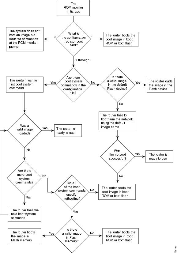
When a router is powered on or rebooted, the following events happen:
•![]() The ROM monitor initializes.
The ROM monitor initializes.
•![]() The ROM monitor checks the boot field (the lowest four bits) in the configuration register.
The ROM monitor checks the boot field (the lowest four bits) in the configuration register.
–![]() If the last digit of the boot field is 0 (for example, 0x100), the system does not boot. Instead the system enters ROM monitor mode and waits for user intervention. From ROM monitor mode, you can manually boot the system using the boot or b command.
If the last digit of the boot field is 0 (for example, 0x100), the system does not boot. Instead the system enters ROM monitor mode and waits for user intervention. From ROM monitor mode, you can manually boot the system using the boot or b command.
–![]() If the last digit of the boot field is1 (for example, 0x101), the boot helper image is loaded from ROM. (On some platforms, the boot helper image is specified by the BOOTLDR environment variable.)
If the last digit of the boot field is1 (for example, 0x101), the boot helper image is loaded from ROM. (On some platforms, the boot helper image is specified by the BOOTLDR environment variable.)
–![]() If the last digit of the boot field is 2 through F (for example, 0x102 through 0x10F), the router boots the first valid image specified in the configuration file or specified by the BOOT environment variable.
If the last digit of the boot field is 2 through F (for example, 0x102 through 0x10F), the router boots the first valid image specified in the configuration file or specified by the BOOT environment variable.

Note ![]() The configuration register boot field value is expressed in hexadecimal. Because the boot field only encompasses the last four bits (represented by the last hexadecimal digit) of the configuration register value, the only digit we are concerned with in this discussion is the last digit. The makes 0x1 (0000 0001) equivalent to 0x101 (1 0000 0001) in discussions of the boot field, as in both cases the last four bits are 0001.
The configuration register boot field value is expressed in hexadecimal. Because the boot field only encompasses the last four bits (represented by the last hexadecimal digit) of the configuration register value, the only digit we are concerned with in this discussion is the last digit. The makes 0x1 (0000 0001) equivalent to 0x101 (1 0000 0001) in discussions of the boot field, as in both cases the last four bits are 0001.
When the boot field is 0x102 through 0x10F, the router goes through each boot system command in order until it boots a valid image. If bit 13 in the configuration register is set, each command will be tried once (bit 13 is indicated by the position occupied by b in the following hexadecimal notation: 0xb000). If bit 13 is not set, the boot system commands specifying a network server will be tried up to five more times. The timeouts between each consecutive attempt are 2, 4, 16, 256, and 300 seconds.
If the router cannot find a valid image, the following events happen:
•![]() If all boot commands in the system configuration file specify booting from a network server and all commands fail, the system attempts to boot the first valid file in Flash memory.
If all boot commands in the system configuration file specify booting from a network server and all commands fail, the system attempts to boot the first valid file in Flash memory.
•![]() If the "boot-default-ROM-software" option in the configuration register is set, the router will start the boot image (the image contained in boot ROM or specified by the BOORLDR environment variable).
If the "boot-default-ROM-software" option in the configuration register is set, the router will start the boot image (the image contained in boot ROM or specified by the BOORLDR environment variable).
•![]() If the "boot-default-ROM-software" option in the configuration register is not set, the system waits for user intervention at the ROM monitor prompt. You must boot the router manually.
If the "boot-default-ROM-software" option in the configuration register is not set, the system waits for user intervention at the ROM monitor prompt. You must boot the router manually.
•![]() If a fully functional system image is not found, the router will not function and must be reconfigured through a direct console port connection.
If a fully functional system image is not found, the router will not function and must be reconfigured through a direct console port connection.
Note ![]() Refer to your platform documentation for information on the default location of the boot image.
Refer to your platform documentation for information on the default location of the boot image.
When looking for a bootable file in Flash memory:
•![]() The system searches for the filename in Flash memory. If a filename is not specified, the software searches through the entire Flash directory for a bootable file instead of picking only the first file.
The system searches for the filename in Flash memory. If a filename is not specified, the software searches through the entire Flash directory for a bootable file instead of picking only the first file.
•![]() The system attempts to recognize the file in Flash memory. If the file is recognized, the software decides whether it is bootable by performing the following checks:
The system attempts to recognize the file in Flash memory. If the file is recognized, the software decides whether it is bootable by performing the following checks:
–![]() For run-from-Flash images, the software determines whether it is loaded at the correct execution address.
For run-from-Flash images, the software determines whether it is loaded at the correct execution address.
–![]() For run-from-RAM images, the software determines whether the system has enough RAM to execute the image.
For run-from-RAM images, the software determines whether the system has enough RAM to execute the image.
Figure 12 illustrates the basic booting decision process.
Figure 12 Booting Process
How the Router Uses the Boot Field
The lowest four bits of the 16-bit configuration register (bits 3, 2, 1, and 0) form the boot field. The following boot field values determine if the router loads an operating system and where it obtains the system image:
•![]() When the entire boot field equals 0-0-0-0 (0x0), the router does not load a system image. Instead, it enters ROM monitor or "maintenance" mode from which you can enter ROM monitor commands to manually load a system image. Refer to the "Manually Booting from Flash Memory in ROMMON" section for details on ROM monitor mode.
When the entire boot field equals 0-0-0-0 (0x0), the router does not load a system image. Instead, it enters ROM monitor or "maintenance" mode from which you can enter ROM monitor commands to manually load a system image. Refer to the "Manually Booting from Flash Memory in ROMMON" section for details on ROM monitor mode.
•![]() When the entire boot field equals 0-0-0-1 (0x1), the router loads the boot helper or rxboot image.
When the entire boot field equals 0-0-0-1 (0x1), the router loads the boot helper or rxboot image.
•![]() When the entire boot field equals a value between 0-0-1-0 (0x2) and 1-1-1-1 (0xF), the router loads the system image specified by boot system commands in the startup configuration file. When the startup configuration file does not contain boot system commands, the router tries to load a default system image stored on a network server.
When the entire boot field equals a value between 0-0-1-0 (0x2) and 1-1-1-1 (0xF), the router loads the system image specified by boot system commands in the startup configuration file. When the startup configuration file does not contain boot system commands, the router tries to load a default system image stored on a network server.
When loading a default system image from a network server, the router uses the configuration register settings to determine the default system image filename for booting from a network server. The router forms the default boot filename by starting with the word cisco and then appending the octal equivalent of the boot field number in the configuration register, followed by a hyphen (-) and the processor type name (cisconn-cpu). See the appropriate hardware installation guide for details on the configuration register and the default filename.
Hardware Versus Software Configuration Register Boot Fields
You modify the boot field from either the hardware configuration register or the software configuration register, depending on the platform.
Most platforms have use a software configuration register. Refer to your hardware documentation for information on the configuration register for your platform.
The hardware configuration register can be changed only on the processor card with dual in-line package (DIP) switches located at the back of the router. For information on modifying the hardware configuration register, refer to the appropriate hardware installation guide.
Environment Variables
Because many platforms can boot images from several locations, these systems use special ROM monitor environment variables to specify the location and filename of images that the router is to use. In addition, Class A Flash file systems can load configuration files from several locations and use an environment variable to specify startup configurations:
•![]() CONFIG_FILE Environment Variable
CONFIG_FILE Environment Variable
•![]() Controlling Environment Variables
Controlling Environment Variables
BOOT Environment Variable
The BOOT environment variable specifies a list of bootable system images on various file systems. Refer to the "Specify the Startup System Image in the Configuration File" section in the "Loading and Maintaining System Images and Microcode" chapter of the Configuration Fundamentals Configuration Guide. After you save the BOOT environment variable to your startup configuration, the router checks the variable upon startup to determine the device and filename of the image to boot.
The router tries to boot the first image in the BOOT environment variable list. If the router is unsuccessful at booting that image, it tries to boot the next image specified in the list. The router tries each image in the list until it successfully boots. If the router cannot boot any image in the BOOT environment variable list, the router attempts to boot the boot image.
If an entry in the BOOT environment variable list does not specify a device, the router assumes the device is tftp. If an entry in the BOOT environment variable list specifies an invalid device, the router skips that entry.
BOOTLDR Environment Variable
The BOOTLDR environment specifies the Flash file system and filename containing the boot image that the ROM monitor uses if it cannot find a valid system image. In addition, a boot image is required to boot the router with an image from a network server.
You can change the BOOTLDR environment variable on platforms that use a software boot image rather than boot ROMs. On these platforms, the boot image can be changed without having to replace the boot ROM.
This environment variable allows you to have several boot images. After you save the BOOTLDR environment variable to your startup configuration, the router checks the variable upon startup to determine which boot image to use if the system cannot be loaded.
Note ![]() Refer to your platform documentation for information on the default location of the boot image.
Refer to your platform documentation for information on the default location of the boot image.
CONFIG_FILE Environment Variable
For Class A Flash file systems, the CONFIG_FILE environment variable specifies the file system and filename of the configuration file to use for initialization (startup). Valid file systems can include nvram:, bootflash:, slot0:, and slot1:. Refer to the "Managing Configuration Files" chapter for more information on devices. After you save the CONFIG_FILE environment variable to your startup configuration, the router checks the variable upon startup to determine the location and filename of the configuration file to use for initialization.
The router uses the NVRAM configuration during initialization when the CONFIG_FILE environment variable does not exist or when it is null (such as at first-time startup). If the router detects a problem with NVRAM or a checksum error, the router enters setup mode. Refer to the "Using Setup for Configuration Changes" chapter in this publication for more information on the setup command facility.
Controlling Environment Variables
Although the ROM monitor controls environment variables, you can create, modify, or view them with certain commands. To create or modify the BOOT, BOOTLDR, and CONFIG_FILE environment variables, use the boot system, boot bootldr, and boot config global configuration commands, respectively.
Refer to the "Specify the Startup System Image in the Configuration File" section in the "Loading and Maintaining System Images" chapter of this book for details on setting the BOOT environment variable. Refer to the "Specify the Startup Configuration File" section in the "Managing Configuration Files" chapter of this document for details on setting the CONFIG_FILE variable.
Note ![]() When you use these three global configuration commands, you affect only the running configuration. You must save the environment variable settings to your startup configuration to place the information under ROM monitor control and for the environment variables to function as expected. Use the copy system:running-config nvram:startup-config command to save the environment variables from your running configuration to your startup configuration.
When you use these three global configuration commands, you affect only the running configuration. You must save the environment variable settings to your startup configuration to place the information under ROM monitor control and for the environment variables to function as expected. Use the copy system:running-config nvram:startup-config command to save the environment variables from your running configuration to your startup configuration.
You can view the contents of the BOOT, BOOTLDR, and the CONFIG_FILE environment variables by issuing the show bootvar command. This command displays the settings for these variables as they exist in the startup configuration as well as in the running configuration if a running configuration setting differs from a startup configuration setting.
Use the more nvram:startup-config command to display the contents of the configuration file pointed to by the CONFIG_FILE environment variable.
Manually Loading a System Image from ROM Monitor
If your router does not find a valid system image, or if its configuration file is corrupted at startup, or the configuration register is set to enter ROM monitor mode, the system enters ROM monitor mode. From this mode, you can manually load a system image from the following locations:
•![]() Internal Flash memory or a Flash memory PC card
Internal Flash memory or a Flash memory PC card
•![]() A network server file
A network server file
•![]() ROM
ROM
•![]() A local or remote computer, using the Xmodem or Ymodem protocol (Cisco 1600 series and Cisco 3600 series routers only)
A local or remote computer, using the Xmodem or Ymodem protocol (Cisco 1600 series and Cisco 3600 series routers only)
You may only boot from a location if the router can store an image there. Therefore, not all platforms can manually load from these locations.
You can also enter ROM monitor mode by restarting the router and then pressing the Break key or issuing a "send break" command from a telnet session during the first 60 seconds of startup.
Aliasing ROM Monitoring Commands
The ROM monitor supports command aliasing modeled on the aliasing function built into the Korn shell. The alias command is used to set and view aliased names. This allows the user to alias command names to a letter or word. Aliasing is often used to shorten command names or automatically invoke command options.
Aliases are stored in NVRAM and remain intact across periods of no power. These are some of the set aliases:
•![]() b—boot
b—boot
•![]() h—history
h—history
•![]() i—intialize/reset
i—intialize/reset
•![]() r—repeat
r—repeat
•![]() k—stack
k—stack
•![]() ?—help
?—help
The following example shows a pre-aliased menu-type list for ROMMON commands:
> ?
$ state Toggle cache state (? for help)
B [filename] [TFTP Server IP address | TFTP Server Name]
Load and execute system image from ROM or from TFTP server
C [address] Continue execution [optional address]
D /S M L V Deposit value V of size S into location L with modifier M
E /S M L Examine location L with size S with modifier M
G [address] Begin execution
H Help for commands
I Initialize
K Stack trace
L [filename] [TFTP Server IP address | TFTP Server Name]
Load system image from ROM or from TFTP server, but do not
begin execution
O Show configuration register option settings
P Set the break point
S Single step next instruction
T function Test device (? for help)
Deposit and Examine sizes may be B (byte), L (long) or S (short).
Modifiers may be R (register) or S (byte swap).
Register names are: D0-D7, A0-A6, SS, US, SR, and PC
If your options appear in the above menu-type format, you can use the listed aliased commands. To initialize the router or access server, enter the i command. The i command causes the bootstrap program to reinitialize the hardware, clear the contents of memory, and boot the system. To boot the system image file, use the b command.
The ROM monitor software characteristics will vary depending on your platform. For further details on ROM monitor mode commands, refer to the appropriate hardware installation guide, or perform a search on Cisco.com.
How to Configure Rebooting and Reloading Procedures
This section contains information about the following:
•![]() Modifying the Configuration Register Boot Field
Modifying the Configuration Register Boot Field
•![]() Setting the BOOTLDR Environment Variable
Setting the BOOTLDR Environment Variable
•![]() Scheduling a Reload of the System Image
Scheduling a Reload of the System Image
•![]() Displaying Information about a Scheduled Reload
Displaying Information about a Scheduled Reload
•![]() Cancelling a Scheduled Reload
Cancelling a Scheduled Reload
•![]() Manually Booting from Flash Memory in ROMMON
Manually Booting from Flash Memory in ROMMON
•![]() Manually Booting from a Network File in ROMMON
Manually Booting from a Network File in ROMMON
•![]() Manually Booting from ROM in ROMMON
Manually Booting from ROM in ROMMON
•![]() Manually Booting Using MOP in ROMMON
Manually Booting Using MOP in ROMMON
Displaying Boot Information
To display information about system software, system image files, and configuration files, complete the tasks in this section:
SUMMARY STEPS
1. ![]() enable
enable
2. ![]() show bootvar
show bootvar
3. ![]() more nvram:startup-config
more nvram:startup-config
4. ![]() show version
show version
DETAILED STEPS
Modifying the Configuration Register Boot Field
To modify the configuration register boot field to determine whether the router loads an operating system image, and if so, where it obtains this system image, complete the tasks in this section:
SUMMARY STEPS
1. ![]() enable
enable
2. ![]() show version
show version
3. ![]() configure terminal
configure terminal
4. ![]() config-register value
config-register value
5. ![]() end
end
6. ![]() show version
show version
7. ![]() copy running-config startup-config
copy running-config startup-config
8. ![]() reload
reload
DETAILED STEPS
Examples
In the following example, the show version command indicates that the current configuration register is set so that the router does not automatically load an operating system image. Instead, it enters ROM monitor mode and waits for user-entered ROM monitor commands. The new setting instructs the router to a load a system image from commands in the startup configuration file or from a default system image stored on a network server.
Router1# show version
Cisco IOS (tm) Software
4500 Software (C4500-J-M), Version 11.1(10.4), RELEASE SOFTWARE
Copyright (c) 1986-1997 by Cisco Systems, Inc.
Compiled Mon 07-Apr-97 19:51 by lmiller
Image text-base: 0x600088A0, data-base: 0x60718000
ROM: System Bootstrap, Version 5.1(1), RELEASE SOFTWARE (fc1)
FLASH: 4500-XBOOT Bootstrap Software, Version 10.1(1), RELEASE SOFTWARE (fc1)
Router1 uptime is 6 weeks, 5 days, 2 hours, 22 minutes
System restarted by error - a SegV exception, PC 0x6070F7AC
System image file is "c4500-j-mz.111-current", booted via flash
cisco 4500 (R4K) processor (revision 0x00) with 32768K/4096K bytes of memory.
Processor board ID 01242622
R4600 processor, Implementation 32, Revision 1.0
G.703/E1 software, Version 1.0.
Bridging software.
SuperLAT software copyright 1990 by Meridian Technology Corp).
X.25 software, Version 2.0, NET2, BFE and GOSIP compliant.
TN3270 Emulation software (copyright 1994 by TGV Inc).
Basic Rate ISDN software, Version 1.0.
2 Ethernet/IEEE 802.3 interfaces.
2 Token Ring/IEEE 802.5 interfaces.
4 ISDN Basic Rate interfaces.
128K bytes of non-volatile configuration memory.
8192K bytes of processor board System flash (Read/Write)
4096K bytes of processor board Boot flash (Read/Write)
Configuration register is 0x2100
Router1# configure terminal
Router1(config)# config-register 0x210F
Router1(config)# end
Router1# reload
Setting the BOOTLDR Environment Variable
To set the BOOTLDR environment variable, complete the tasks in this section:
SUMMARY STEPS
1. ![]() enable
enable
2. ![]() dir [flash-filesystem:]
dir [flash-filesystem:]
3. ![]() boot bootldr file-url
boot bootldr file-url
4. ![]() end
end
5. ![]() copy system:running-config nvram:startup-config
copy system:running-config nvram:startup-config
6. ![]() show bootvar
show bootvar
Examples
The following example sets the BOOTLDR environment to change the location of the boot helper image from internal Flash to slot 0:
Router# dir bootflash:
-#- -length- -----date/time------ name
1 620 May 04 1995 26:22:04 rsp-boot-m
2 620 May 24 1995 21:38:14 config2
7993896 bytes available (1496 bytes used)
Router# configure terminal
Router (config)# boot bootldr slot0:rsp-boot-m
Router (config)# end
Router# copy system:running-config nvram:startup-config
[ok]
Router# show bootvar
BOOT variable = slot0:rsp-boot-m
CONFIG_FILE variable = nvram:
Current CONFIG_FILE variable = slot0:router-config
Configuration register is 0x0
Scheduling a Reload of the System Image
To schedule a reload of the system image to occur on the router at a later time (for example, late at night or during the weekend when the router is used less) or to synchronize a reload network-wide (for example, to perform a software upgrade on all routers in the network), complete the task in this section.
Restrictions
A scheduled reload must take place within approximately 24 days.
SUMMARY STEPS
1. ![]() enable
enable
2. ![]() reload in [hh:]mm [text]
reload in [hh:]mm [text]
3. ![]() reload at hh:mm [month day | day month] [text]
reload at hh:mm [month day | day month] [text]
DETAILED STEPS
|
|
|
|
|---|---|---|
Step 1 |
enable Router> enable |
Enables privileged EXEC mode. • |
Step 2 |
reload in [hh:]mm [text]
Router# reload in 05:00 |
Schedules a reload of the software to take effect in mm minutes (or hh hours and mm minutes) from now. |
Step 3 |
reload at hh:mm [month day | day month] [text] Router# reload at 02:00 jun 20 |
Schedules a reload of the software to take place at the specified time (using a 24-hour clock). If you specify the month and day, the reload is scheduled to take place at the specified time and date. If you do not specify the month and day, the reload takes place at the specified time on the current day (if the specified time is later than the current time), or on the next day (if the specified time is earlier than the current time). Specifying 00:00 schedules the reload for midnight. Note |
Examples
The following example illustrates how to use the reload command to reload the software on the router on the current day at 7:30 p.m.:
Router# reload at 19:30
Reload scheduled for 19:30:00 UTC Wed Jun 5 1996 (in 2 hours and 25 minutes)
Proceed with reload? [confirm]
The following example illustrates how to use the reload command to reload the software on the router at a future time:
Router# reload at 02:00 jun 20
Reload scheduled for 02:00:00 UTC Thu Jun 20 1996 (in 344 hours and 53 minutes)
Proceed with reload? [confirm]
Displaying Information about a Scheduled Reload
To display information about a previously scheduled reload or to determine if a reload has been scheduled on the router, complete the task in this section:
SUMMARY STEPS
1. ![]() enable
enable
2. ![]() show reload
show reload
DETAILED STEPS
Cancelling a Scheduled Reload
To cancel a previously scheduled reload, complete the task in this section:
SUMMARY STEPS
1. ![]() enable
enable
2. ![]() reload cancel
reload cancel
DETAILED STEPS
Examples
The following example illustrates how to use the reload cancel command to stop a scheduled reload:
Router# reload cancel
Router#
***
*** --- SHUTDOWN ABORTED ---
***
Entering ROM Monitor Mode
During the first 60 seconds of startup, you can force the router to stop booting. The router will enter ROM monitor mode, where you can change the configuration register value or boot the router manually. To stop booting and enter ROM monitor mode, complete the tasks in this section:
SUMMARY STEPS
1. ![]() enable
enable
2. ![]() reload
reload
3. ![]() Press the Break key during the first 60 seconds while the system is booting.
Press the Break key during the first 60 seconds while the system is booting.
4. ![]() ?
?
DETAILED STEPS
What to Do Next
If you are planning to use ROM monitor mode on a regular basis, or wish users to load using ROM monitor commands, you can configure the system to default to ROMMON. To automatically boot your system in ROM monitor mode, reset the configuration register to 0x0 by using the config-register 0x0 configuration command. The new configuration register value, 0x0, takes effect after the router or access server is rebooted with the reload command. If you set the configuration to 0x0, you will have to manually boot the system from the console each time you reload the router or access server.
To exit ROMMON mode, use the continue command. If you have changed the configuration, use the copy running-config startup-config command and then issue the reload command to save your configuration changes.
Manually Booting from Flash Memory in ROMMON
To manually boot from Flash memory, complete the tasks in Step 1, 2, and 3, and then one of the commands in Step 4:
DETAILED STEPS
Examples
In the following example, a router is manually booted from Flash memory. Because the optional filename argument is absent, the first valid file in Flash memory is loaded.
> boot flash
F3: 1858656+45204+166896 at 0x1000
Booting gs7-k from flash memory RRRRRRRRRRRRRRRRRRRRRRRRRRRRRRRRRRRRR
RRRRRRRRRRRRRRRRRRRRRRRRRRRRRRRRRRRRRRRRRRRRRRRRRRRRRRRRRRRRRRRRRRRRRRRRRRRRRRRRRRRRRR
RRRRRRRRRRRRRRRRRRRRRRRRRRRRRRRRRRRRRRRRRRRRRRRRRRRRRRRRRRRRRRRRRRRRRRRRRRRRRRRRRRRRRR
RRRRRRRRRRRRRRRRRRRRRRRRRRRRRRRRRRRRRRRRRRRRRRRRRRRRRRRRRRRRRRRRRRRRRRRRRRRRRRRRRRRRRR
RRRRRRRRRRRRRRRRRRRRRRRRRRRRRRRRRRRRRRRRRRRRRRRRRRRRRRRRRRRRRRRRRRRRRRRRRRRR [OK -
1903912/13765276 bytes]
F3: 1858676+45204+166896 at 0x1000
Restricted Rights Legend
Use, duplication, or disclosure by the Government is
subject to restrictions as set forth in subparagraph
(c) of the Commercial Computer Software - Restricted
In the following example, the boot flash command is used with the filename gs7-k—the name of the file that is loaded:
> boot flash gs7-k
F3: 1858656+45204+166896 at 0x1000
Booting gs7-k from flash memory RRRRRRRRRRRRRRRRRRRRRRRRRRRRRRRRRRRRR
RRRRRRRRRRRRRRRRRRRRRRRRRRRRRRRRRRRRRRRRRRRRRRRRRRRRRRRRRRRRRRRRRRRRRRRRRRRRRRRR
RRRRRRRRRRRRRRRRRRRRRRRRRRRRRRRRRRRRRRRRRRRRRRRRRRRRRRRRRRRRRRRRRRRRRRRRRRRRRRRR
RRRRRRRRRRRRRRRRRRRRRRRRRRRRRRRRRRRRRRRRRRRRRRRRRRRRRRRRRRRRRRRRRRRRRRRRRRRRRRRR
RRRRRRRRRRRRRRRRRRRRRRRRRRRRRRRRRRRRRRRRRRRRRRRRRRRRRRRRRRRRRRRRRRRRRRRRRRRRRRRR
RRRRRRRRRRRRRR [OK - 1903912/13765276 bytes]
F3: 1858676+45204+166896 at 0x1000
Restricted Rights Legend
Use, duplication, or disclosure by the Government is
subject to restrictions as set forth in subparagraph
(c) of the Commercial Computer Software - Restricted
System Bootstrap, Version 4.6(1012) [mlw 99], INTERIM SOFTWARE
Copyright (c) 1986-1992 by cisco Systems
RP1 processor with 16384 Kbytes of memory
The following command instructs the ROM monitor to boot the first file in the first partition of internal Flash memory:
> boot flash:
This command instructs the ROM monitor to boot the first file in the second partition of the Flash memory card in slot 0:
> boot slot0:2:
In this example, the ROM monitor boots the file named image name from the third partition of the Flash memory card in slot 0:
> boot slot0:3:imagename
The following command fails to specify a valid device type (flash:, slot0:, or slot1:), so the ROM monitor invokes the boot helper to boot a system image.
> boot flash
Manually Booting from a Network File in ROMMON
To manually boot from a network file, complete the task in this section:
SUMMARY STEPS
1. ![]() enable
enable
2. ![]() reload
reload
3. ![]() Press the Break key during the first 60 seconds while the system is booting.
Press the Break key during the first 60 seconds while the system is booting.
or
config-register 0x0
4. ![]() boot filename [ip-address]
boot filename [ip-address]
DETAILED STEPS
Examples
In the following example, a router is manually booted from the network file network1:
ROMMON>boot network1
Manually Booting from ROM in ROMMON
To manually boot the router from ROM, complete the task in this section:
SUMMARY STEPS
1. ![]() enable
enable
2. ![]() reload
reload
3. ![]() Press the Break key during the first 60 seconds while the system is booting.
Press the Break key during the first 60 seconds while the system is booting.
or
config-register 0x0
4. ![]() boot filename [ip-address]
boot filename [ip-address]
DETAILED STEPS
Examples
In the following example, a router is manually booted from ROM:
ROMMON> boot
Manually Booting Using MOP in ROMMON
You can interactively boot system software using MOP. Typically, you do this to verify that system software has been properly installed on the MOP boot server before configuring the router to automatically boot the system software image. To manually boot the router using MOP, complete the task in this section:
SUMMARY STEPS
1. ![]() enable
enable
2. ![]() reload
reload
3. ![]() Press the Break key during the first 60 seconds while the system is booting.
Press the Break key during the first 60 seconds while the system is booting.
or
config-register 0x0
4. ![]() boot system mop filename [mac-address] [interface]
boot system mop filename [mac-address] [interface]
DETAILED STEPS
Examples
In the following example, a router is manually booted from a MOP server:
ROMMON> boot mop network1
Exiting from ROMMON
To return to EXEC mode from the ROM monitor, you must continue loading from the default system image. To exit ROMMON mode and resume loading, use the following command in ROM monitor mode:
DETAILED STEPS
|
|
|
|---|---|
continue ROMMON > continue |
Resumes loading the startup configuration file and brings the user to EXEC mode. |
 Feedback