Prerequisites for Configuring Multicast Admission Control
IP multicast is enabled and the Protocol Independent Multicast (PIM) interfaces are configured using the tasks described in the “Configuring Basic IP Multicast” module.
The documentation set for this product strives to use bias-free language. For the purposes of this documentation set, bias-free is defined as language that does not imply discrimination based on age, disability, gender, racial identity, ethnic identity, sexual orientation, socioeconomic status, and intersectionality. Exceptions may be present in the documentation due to language that is hardcoded in the user interfaces of the product software, language used based on RFP documentation, or language that is used by a referenced third-party product. Learn more about how Cisco is using Inclusive Language.
This module describes how to implement multicast admission control in an IP multicast network. Multicast admission control features are configured on multicast-enabled routers to prevent control plane overload, ensure proper resource allocation, and provide multicast Call Admission Control (CAC) capabilities.
IP multicast is enabled and the Protocol Independent Multicast (PIM) interfaces are configured using the tasks described in the “Configuring Basic IP Multicast” module.
As the popularity of network video applications grows among consumers, admission control functions--which govern transmission and reception of multicast traffic based on available network resources--are vital. Without admission control, some users may receive degraded multicast streams, rendering programs unwatchable, and others may receive a “Network Busy” message or nothing at all as network resources are overtaxed. Network admission control is important in maintaining a high quality of experience for digital video consumers.
The goals of multicast admission control features, therefore, are as follows:
Protect the router from control plane overload to ensure that memory and CPU resources on multicast-enabled routers are not overrun by multicast route (mroute) states or denial-of-service (DoS) attacks from multicast packets.
Enable proper resource allocation (on a global, per MVRF, or per interface basis) to ensure that multicast services are delivered to subscribers per their IP Service Level Agreements (SLAs) and to minimize the effects of DoS attacks on subscribers.
Provide multicast CAC capabilities to prevent bandwidth resources (interfaces, subnetworks) from being congested and to enable service providers to offer more flexible and refined content and subscriber-based policies.
 Note |
After EFP shut, unknown multicast packets are dropped and only control packets are allowed. |
The Cisco IOS software supports the following multicast admission control features:
Global and Per MVRF Mroute State Limit
The ip multicast route-limit command allows for the configuration of global and per MVRF state limiters, which impose limits on the number of multicast routes (mroutes) that can be added to the global table or to a particular Multicast Virtual Routing and Forwarding (MVRF) table.
IGMP State Limit
This feature allows for the configuration of IGMP state limiters, which impose limits on mroute states resulting from Internet Group Management Protocol (IGMP) membership reports (IGMP joins).
Per Interface Mroute State Limit
This feature allows for the configuration of per interface mroute state limiters, which impose mroute state limits for different access control list (ACL)-classified sets of multicast traffic on an interface.
Bandwidth-Based CAC for IP Multicast
This feature allows for the configuration of bandwidth-based multicast CAC policies, which allow for bandwidth-based CAC on a per interface basis.
These admission control features may be invoked by service providers and enterprise network administrators based on different criteria, including the service package an end user has purchased or the privileges an enterprise user is entitled to.
The ip multicast route-limit command allows for the configuration of global and per MVRF mroute state limiters, which impose limits on the number of mroutes that can be added to the global table or to a particular MVRF table, respectively.
Global mroute state limiters are used to limit the number of mroutes that can be added to the global table on a router. Configuring a global mroute state limiter can protect a router in the event of a multicast DoS attack (by preventing mroutes from overrunning the router).
Per VRF mroute state limiters are used to limit the number of mroutes that can be added to an MVRF table on a Multicast VPN (MVPN) provider edge (PE) router. Configuring per MVRF mroute state limits can be used to ensure the fair sharing of mroutes between different MVRFs on an MVPN PE router.
Global and per MVRF mroute state limiters are configured using the ip multicast route-limit command in global configuration mode. The syntax of the ip multicast route-limit command is as follows:
ip multicast [vrf vrf-name ] route-limit limit [threshold ]
Issuing the ip multicast route-limit command without the optional vrf keyword and vrf-name arguments configures a global mroute state limiter. The optional vrf keyword and vrf-name arguments are used with the ip multicast limit command to configure per MVRF mroute state limiters.
Note |
When configuring global and per VRF mroute state limiters, you can only configure one limit for the global table and one limit per MVRF table. |
The value specified for the required limit argument defines the maximum number of mroutes that can be added to either the global table or a particular MVRF table, respectively.
Note |
Global and per MVRF mroute state limiters operate independently and can be used alone or together, depending upon the admission control requirements of your network. |
In addition, for both global and per MVRF mroute state limiters, the optional threshold argument is available to set mroute threshold limits.
The mechanics of global and per MVRF mroute state limiters are as follows:
Each time the state for an mroute is created on a router, the Cisco IOS software checks to see if the limit for the global mroute state limiter (if the mroute is associated with the global table) or the limit for the per MVRF mroute state limiter (if the mroute is associated with the MVRF table) has been reached.
States for mroutes that exceed the configured limit for the global or the per MVRF mroute state limiter are not created on the router, and a warning message in the following format is generated:
% MROUTE-4-ROUTELIMIT : <current mroute count> exceeded multicast route-limit of
<mroute limit value>
When an mroute threshold limit is also configured for the global or the per MVRF mroute state limiter, each time the state for an mroute is created on a router, the Cisco IOS software also checks to see if the mroute threshold limit has been reached. If the mroute threshold limit is exceeded, a warning message in the following format is generated:
% MROUTE-4-ROUTELIMITWARNING : multicast route-limit warning <current mroute count> threshold <mroute threshold value>
Warning messages continue to be generated until the number of mroutes exceeds the configured limit or until the number of mroute states falls below the configured mroute threshold limit.
The IGMP State Limit feature allows for the configuration of IGMP state limiters, which impose limits on mroute states resulting from IGMP membership reports (IGMP joins) on a global or per interface basis. Membership reports exceeding the configured limits are not entered into the IGMP cache. This feature can be used to prevent DoS attacks or to provide a multicast CAC mechanism in network environments where all the multicast flows roughly utilize the same amount of bandwidth.
Note |
IGMP state limiters impose limits on the number of mroute states resulting from IGMP, IGMP v3lite, and URL Rendezvous Directory (URD) membership reports on a global or per interface basis. |
Configuring IGMP state limiters in global configuration mode specifies a global limit on the number of IGMP membership reports that can be cached.
Configuring IGMP state limiters in interface configuration mode specifies a limit on the number of IGMP membership reports on a per interface basis.
Use ACLs to prevent groups or channels from being counted against the interface limit. A standard or an extended ACL can be specified. A standard ACL can be used to define the (*, G) state to be excluded from the limit on an interface. An extended ACLs can be used to define the (S, G) state to be excluded from the limit on an interface. An extended ACL also can be used to define the (*, G) state to be excluded from the limit on an interface, by specifying 0.0.0.0 for the source address and source wildcard--referred to as (0, G)--in the permit or deny statements that compose the extended access list.
You can only configure one global limit per device and one limit per interface.
The mechanics of IGMP state limiters are as follows:
Each time a router receives an IGMP membership report for a particular group or channel, the Cisco IOS software checks to see if either the limit for the global IGMP state limiter or the limit for the per interface IGMP state limiter has been reached.
%IGMP-6-IGMP_GROUP_LIMIT: IGMP limit exceeded for <group (*, group address)> on <interface type number> by host <ip address>
%IGMP-6-IGMP_CHANNEL_LIMIT: IGMP limit exceeded for <channel (source address, group address)> on <interface type number> by host <ip address>
If only per interface IGMP state limiters are configured, then each limit is only counted against the interface on which it was configured.
If both a global IGMP state limiter and per interface IGMP state limiters are configured, the limits configured for the per interface IGMP state limiters are still enforced but are constrained by the global limit.
The Per Interface Mroute State Limit feature provides the capability to limit the number of mroute states on an interface for different ACL-classified sets of multicast traffic. This feature can be used to prevent DoS attacks or to provide a multicast CAC mechanism when all the multicast flows roughly utilize the same amount of bandwidth.
The Per Interface Mroute State Limit feature essentially is a complete superset of the IGMP State Limit feature (with the exception that it does not support a global limit). The Per Interface Mroute State Limit feature, moreover, is more flexible and powerful (albeit more complex) than the IGMP State Limit feature but is not intended to be a replacement for it because there are applications that suit both features.
The main differences between the Per Interface Mroute State Limit feature and the IGMP State Limit feature are as follows:
The Per Interface Mroute State Limit feature allows multiple limits to be configured on an interface, whereas the IGMP State Limit feature allows only one limit to be configured on an interface. The Per Interface Mroute State Limit feature, thus, is more flexible than the IGMP State Limit feature in that it allows multiple limits to be configured for different sets of multicast traffic on an interface.
The Per Interface Mroute State Limit feature can be used to limit both IGMP and PIM joins, whereas the IGMP State Limit feature can only be used to limit IGMP joins. The IGMP State Limit feature, thus, is more limited in application in that it is best suited to be configured on an edge router to limit the number of groups that receivers can join on an outgoing interface. The Per Interface Mroute State Limit feature has a wider application in that it can be configured to limit IGMP joins on an outgoing interface, to limit PIM joins (for Any Source Multicast [ASM] groups or Source Specific Multicast [SSM] channels) on an outgoing interface connected to other routers, to limit sources behind an incoming interface from sending multicast traffic, or to limit sources directly connected to an incoming interface from sending multicast traffic.
Note |
Although the PIM Interface Mroute State Limit feature allows you to limit both IGMP and PIM joins, it does not provide the capability to limit PIM or IGMP joins separately because it does not take into account whether the state is created as a result of an IGMP or PIM join. As such, the IGMP State Limit feature is more specific in application because it specifically limits IGMP joins. |
The Per Interface Mroute State Limit feature allows you to specify limits according to the direction of traffic; that is, it allows you to specify limits for outgoing interfaces, incoming interfaces, and for incoming interfaces having directly connected multicast sources. The IGMP State Limit feature, however, only can be used to limit outgoing interfaces. The Per Interface State Mroute State Limit feature, thus, is wider in scope in that it can be used to limit mroute states for both incoming and outgoing interfaces from both sources and receivers, whereas the IGMP State Limit feature is more narrow in scope in that it can only be used to limit mroute states for receivers on an LAN by limiting the number of IGMP joins on an outgoing interface.
Both the IGMP State Limit and Per Interface Mroute State Limit features provide a rudimentary multicast CAC mechanism that can be used to provision bandwidth utilization on an interface when all multicast flows roughly utilize the same amount of bandwidth. The Bandwidth-Based CAC for IP Multicast feature, however, offers a more flexible and powerful alternative for providing multicast CAC in network environments where IP multicast flows utilize different amounts of bandwidth.
The Per Interface Mroute State Limit feature is configured using the ip multicast limit command in interface configuration mode. An ip multicast limit command configured on an interface is called an per interface mroute state limiter. A per interface mroute state limiter is defined by direction, ACL, and maximum number of mroutes. Each per interface mroute state limiter maintains a counter to ensure that the maximum number of mroutes is not exceeded.
The following forms of the ip multicast limit command are available to configure per interface mroute state limiters:
ip multicast limit access-list max-entries
This command limits mroute state creation for an ACL-classified set of traffic on an interface when the interface is an outgoing (egress) interface, and limits mroute outgoing interface list (olist) membership when the interface is an incoming (ingress) Reverse Path Forwarding (RPF) interface.
This type of per interface mroute state limiter limits mroute state creation--by accounting each time an mroute permitted by the ACL is created or deleted--and limits mroute olist membership--by accounting each time that an mroute olist member permitted by the ACL is added or removed.
Entering this form of the command (that is, with no optional keywords) is equivalent to specifying the ip multicast limit rpf and ip multicast limit out forms of the command.
ip multicast limit connected access-list max-entries
This command limits mroute state creation for an ACL-classified set of multicast traffic on an incoming (RPF) interface that is directly connected to a multicast source by accounting each time that an mroute permitted by the ACL is created or deleted.
ip multicast limit out access-list max-entries
This command limits mroute olist membership on an outgoing interface for an ACL-classified set of multicast traffic by accounting each time that an mroute olist member permitted by the ACL is added or removed.
ip multicast limit rpf access-list max-entries
This command limits mroute state creation for an ACL-classified set of multicast traffic on an incoming (RPF) interface by accounting each time an mroute permitted by the ACL is created or deleted.
For the required access-list argument, specify the ACL that defines the IP multicast traffic to be limited on an interface. A standard or extended ACL can be specified. Standard ACLs can be used to define the (*, G) state to be limited on an interface. Extended ACLs can be used to define the (S, G) state to be limited on an interface. Extended ACLs also can be used to define the (*, G) state to be limited on an interface, by specifying 0.0.0.0 for the source address and source wildcard--referred to as (0, G)--in the permit or deny statements that compose the extended access list.
The mechanics of per interface mroute state limiters are as follows:
Each time the state for an mroute is created or deleted and each time an olist member is added or removed, the software searches for a corresponding per interface mroute state limiter that matches the mroute.
When an mroute is created or deleted, the software searches for a per interface mroute state limiter configured on the incoming (RPF) interface that matches the mroute to be created or deleted. When an olist member is added or removed, the software searches for a per interface mroute state limiter configured on the outgoing interface that matches the mroute to be added or removed.
A top-down search is performed using the list of configured per interface mroute state limiters. Only per interface mroute state limiters that match the direction of traffic are considered. The first per interface mroute state limiter that matches is used for limiting (sometimes referred to as accounting). A match is found when the ACL permits the mroute state.
When a match is found, the counter of the per interface mroute state limiter is updated (increased or decreased). If no per interface mroute state limiter is found that matches an mroute, no accounting is performed for the mroute (because there is no counter to update).
The amount with which to update the counter is called the cost (sometimes referred to as the cost multiplier). The default cost is 1.
Note |
A per interface mroute state limiter always allows the deletion of an mroute or the removal of an interface from the olist. In those cases, the respective per interface mroute state limiter decreases the counter by the value of the cost multiplier. In addition, RPF changes to an existing mroute are always allowed (in order to not affect existing traffic). However, a per interface mroute state limiter only allows the creation of an mroute or the addition of an mroute olist member if adding the cost does not exceed the maximum number of mroutes permitted. |
To ensure that all mroutes are accounted, you can configure a per interface mroute state limiter whose ACL contains a permit-any statement and set the value of zero (0) for maximum entries. Configuring an mroute state limiter in this manner effectively denies all fall through states, which may be a way to prevent a multicast DoS attack in and out of the interface.
When creating an ACL, remember that, by default, the end of the ACL contains an implicit deny-any statement for everything if it did not find a match before reaching the end.
An explicit deny statement for a specific mroute in an ACL can be used to specify the state that will not match the ACLwhich will prevent the ACL from being accounted. If an mroute matches a deny statement, the search immediately continues to the next configured mroute state limiter. Configuring an explicit deny statement in an ACL can be more efficient than forcing the mroute to fall through an ACL by using an implicit deny-any statement at the end of the ACL.
Perform the following optional tasks to configure global and per MVRF mroute state limiters.
Global mroute state limiters are used to limit the number of mroutes that can be added to the global table on a router. Configuring a global mroute state limiter can protect a router in the event of a multicast DoS attack (by preventing mroutes from overrunning the router).
Per VRF mroute state limiters are used to limit the number of mroutes that can be added to an MVRF table on an MVPN PE router. Configuring per MVRF mroute state limits can be used to ensure the fair sharing of mroutes between different MVRFs on an MVPN PE router.
Note |
Global and per MVRF mroute state limiters operate independently and can be used alone or together, depending upon the admission control requirements of your network. |
Note |
When configuring global and per VRF mroute state limiters, you can only configure one limit for the global table and one limit per MVRF table. |
The following tasks explain how to configure global and per MVRF mroute state limiters:
These tasks assume that IP multicast has been enabled and that the PIM interfaces have been configured using the tasks described in the “ Configuring Basic IP Multicast ” module.
Before configuring per MVRF mroute state limiters, the MVRFs on the PE router must be configured using the tasks described in the “ Configuring Multicast VPN ” module.
Perform this task to limit the number of mroutes that can be added to the global table. States for mroutes that exceed the global mroute limit will not be created.
| Command or Action | Purpose | |
|---|---|---|
|
Step 1 |
enable Example: |
Enables privileged EXEC mode.
|
|
Step 2 |
configure terminal Example: |
Enters global configuration mode. |
|
Step 3 |
ip multicast route-limit limit [threshold ] Example: |
Limits the number of mroutes that can be added to the global table.
|
|
Step 4 |
end Example: |
Ends the current configuration session and returns to privileged EXEC mode. |
|
Step 5 |
show ip mroute count Example: |
(Optional) Displays mroute data and packet count statistics.
|
Proceed to the Configuring Per MVRF Mroute State Limiters task to configure per MVRF mroute state limiters on a PE router.
Perform this optional task to configure per MVRF mroute state limiters to limit the number of mroutes that can be added to a particular MVRF table. This feature can be configured on a PE router to ensure the fair sharing of mroutes between different MVRFs on the router. States for mroutes that exceed the per MVRF mroute limiter are not created.
| Command or Action | Purpose | |
|---|---|---|
|
Step 1 |
enable Example: |
Enables privileged EXEC mode.
|
|
Step 2 |
configure terminal Example: |
Enters global configuration mode. |
|
Step 3 |
ip multicast vrf vrf-name route-limit limit [threshold ] Example: |
Limits the number of mroutes that can be added to a particular MVRF table.
|
|
Step 4 |
Repeat Step 3 to configure additional per VRF mroute state limiters for other VRFs on an MVPN PE router. |
-- |
|
Step 5 |
end Example: |
Ends the current configuration session and returns to privileged EXEC mode. |
|
Step 6 |
show ip mroute vrf vrf-name count Example: |
(Optional) Displays mroute data and packet count statistics related to the specified MVRF.
|
Note |
IGMP state limiters impose limits on the number of mroute states resulting from IGMP, IGMP v3lite, and URD membership reports on a global or per interface basis. |
These tasks assume that IP multicast has been enabled and that the PIM interfaces have been configured using the tasks described in the “ Configuring Basic IP Multicast ” module.
All ACLs you intend to apply to per interface IGMP state limiters should be configured prior to beginning this configuration task; otherwise, IGMP membership reports for all groups and channels are counted against the configured limits. For information about how to configure ACLs, see the “ Creating an IP Access List and Applying It to an Interface ” module.
Perform this optional task to configure one global IGMP state limiter per device.
| Command or Action | Purpose | |
|---|---|---|
|
Step 1 |
enable Example: |
Enables privileged EXEC mode.
|
|
Step 2 |
configure terminal Example: |
Enters global configuration mode. |
|
Step 3 |
ip igmp limit number Example: |
Configures a global limit on the number of mroute states resulting from IGMP membership reports (IGMP joins). |
|
Step 4 |
end Example: |
Ends the current configuration session and returns to privileged EXEC mode. |
|
Step 5 |
show ip igmp groups Example: |
(Optional) Displays the multicast groups with receivers that are directly connected to the device and that were learned through IGMP. |
Proceed to the Configuring Per Interface IGMP State Limiters task to configure per interface IGMP state limiters.
Perform this optional task to configure a per interface IGMP state limiter.
| Command or Action | Purpose | |
|---|---|---|
|
Step 1 |
enable Example: |
Enables privileged EXEC mode.
|
|
Step 2 |
configure terminal Example: |
Enters global configuration mode. |
|
Step 3 |
interface type number Example: |
Enters interface configuration mode.
|
|
Step 4 |
ip igmp limit number [except access-list ] Example: |
Configures a per interface limit on the number of mroutes states created as a result of IGMP membership reports (IGMP joins). |
|
Step 5 |
Do one of the following:
Example: |
|
|
Step 6 |
show ip igmp interface [type number ] Example: |
(Optional) Displays information about the status and configuration of IGMP and multicast routing on interfaces. |
|
Step 7 |
show ip igmp groups Example: |
(Optional) Displays the multicast groups with receivers that are directly connected to the device and that were learned through IGMP. |
Perform this task to prevent DoS attacks or to provide a multicast CAC mechanism for controling bandwidth when all multicast flows utilize approximately the same amount of bandwidth.
All ACLs to be applied to per interface mroute state limiters must be configured prior to beginning this configuration task; otherwise, the limiters are ignored. For information about how to configure ACLs, see the “ Creating an IP Access List and Applying It to an Interface ” module of the Security Configuration Guide: Access Control Lists guide.
| Command or Action | Purpose | |
|---|---|---|
|
Step 1 |
enable Example: |
Enables privileged EXEC mode.
|
|
Step 2 |
configure terminal Example: |
Enters global configuration mode. |
|
Step 3 |
interface type number Example: |
Enters interface configuration mode for the specified interface type and number. |
|
Step 4 |
ip multicast limit [connected | out | rpf ] access-list max-entries Example: |
Configures per interface mroute state limiters. |
|
Step 5 |
Repeat Step 4 to configure additional per interface mroute state limiters on this interface. |
-- |
|
Step 6 |
Repeat Steps 3 and Step 4 to configure per interface mroute state limiters on additional interfaces. |
-- |
|
Step 7 |
end Example: |
Returns to privileged EXEC mode. |
Proceed to the Monitoring Per Interface Mroute State Limiters and Bandwidth-Based Multicast CAC Policies task to monitor per interface mroute state limiters.
Perform this optional task to monitor per interface mroute state limiters and bandwidth-based multicast CAC policies.
|
Step 1 |
enable Example:Enables privileged EXEC mode.
|
|
Step 2 |
debug ip mrouting limits [group-address ] Displays debugging information about configured per interface mroute state limiters and bandwidth-based multicast CAC policies. The following output is from the debug ip mrouting limits command. The output displays the following events:
Example: |
|
Step 3 |
show ip multicast limit type number Displays counters related to mroute state limiters configured on the interfaces on the router. For each per interface mroute state limiter shown in the output, the following information is displayed:
The following is sample output from the show ip multicast limit command with the type number arguments. In this example, information about mroute state limiters configured on Gigabit Ethernet interface 0/0 is displayed. Example: |
|
Step 4 |
clear ip multicast limit [type number ] Resets the exceeded counter for per interface mroute state limiters. The following example shows how to reset exceeded counters for per interface mroute state limiters configured on Gigabit Ethernet interface 0/0: Example: |
The following example shows how to configure a global mroute state limiter. In this example, a global mroute state limiter is configured with an mroute limit of 1500 and an mroute threshold limit of 1460.
ip multicast route-limit 1500 1460
The following is a sample mroute threshold warning message. The output shows that the configured mroute threshold limit of 1460 has been exceeded by one mroute.
%MROUTE-4-ROUTELIMITWARNING : multicast route-limit warning 1461 threshold 1460
The following is a sample mroute exceeded warning message. The output shows that the configured mroute limit of 1500 has been exceeded by one mroute. States for mroutes that exceed the configured limit for the global mroute state limiter are not created on the router.
%MROUTE-4-ROUTELIMIT : 1501 routes exceeded multicast route-limit of 1500The following example shows how to configure IGMP state limiters to provide multicast CAC in a network environment where all the multicast flows roughly utilize the same amount of bandwidth.
This example uses the topology illustrated in the figure.
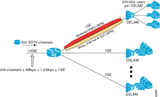
In this example, a service provider is offering 300 Standard Definition (SD) TV channels. Each SD channel utilizes approximately 4 Mbps.
The service provider must provision the Gigabit Ethernet interfaces on the PE device connected to the Digital Subscriber Line Access Multiplexers (DSLAMs) as follows: 50% of the link’s bandwidth (500 Mbps) must be available to subscribers of the Internet, voice, and video on demand (VoD) service offerings while the remaining 50% (500 Mbps) of the link’s bandwidth must be available to subscribers of the SD channel offerings.
Because each SD channel utilizes the same amount of bandwidth (4 Mbps), per interface IGMP state limiters can be used to provide the necessary CAC to provision the services being offered by the service provider. To determine the required CAC needed per interface, the total number of channels is divided by 4 (because each channel utilizes 4 Mbps of bandwidth). The required CAC needed per interface, therefore, is as follows:
500Mbps / 4Mbps = 125 mroutes
Once the required CAC is determined, the service provider uses the results to configure the per IGMP state limiters required to provision the Gigabit Ethernet interfaces on the PE device. Based on the network’s CAC requirements, the service provider must limit the SD channels that can be transmitted out a Gigabit Ethernet interface (at any given time) to 125. Configuring a per interface IGMP state limit of 125 for the SD channels provisions the interface for 500 Mbps of bandwidth, the 50% of the link’s bandwidth that must always be available (but never exceeded) for the SD channel offerings.
The following configuration shows how the service provider uses a per interface mroute state limiter to provision interface Gigabit Ethernet 0/0 for the SD channels and Internet, Voice, and VoD services being offered to subscribers:
interface GigabitEthernet0/0
description --- Interface towards the DSLAM ---
.
.
.
ip igmp limit 125The following example shows how to configure per interface mroute state limiters to provide multicast CAC in a network environment where all the multicast flows roughly utilize the same amount of bandwidth.
This example uses the topology illustrated in the figure.
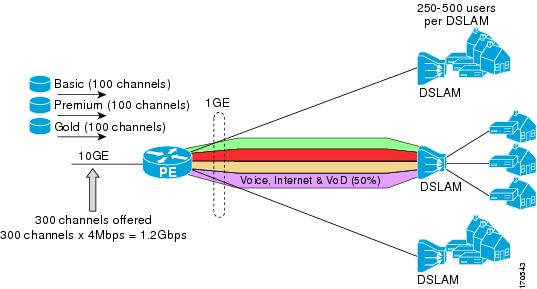
In this example, a service provider is offering 300 SD TV channels. The SD channels are being offered to customers in three service bundles (Basic, Premium, and Gold), which are available to customers on a subscription basis. Each bundle offers 100 channels to subscribers, and each channel utilizes approximately 4 Mbps of bandwidth.
The service provider must provision the Gigabit Ethernet interfaces on the PE device connected to DSLAMs as follows: 50% of the link’s bandwidth (500 Mbps) must be available to subscribers of their Internet, voice, and VoD service offerings while the remaining 50% (500 Mbps) of the link’s bandwidth must be available to subscribers of their SD channel bundle service offerings.
For the 500 Mbps of the link’s bandwidth that must always be available to (but must never be exceeded by) the subscribers of the SD channel bundles, the interface must be further provisioned as follows:
60% of the bandwidth must be available to subscribers of the basic service (300 Mbps).
20% of the bandwidth must be available to subscribers of the premium service (100 Mbps).
20% of the bandwidth must be available to subscribers of the gold service (100 Mbps).
Because each SD channel utilizes the same amount of bandwidth (4 Mbps), per interface mroute state limiters can be used to provide the necessary CAC to provision the services being offered by the service provider. To determine the required CAC needed per interface, the number of channels for each bundle is divided by 4 (because each channel utilizes 4 Mbps of bandwidth). The required CAC needed per interface, therefore, is as follows:
Basic Services: 300 / 4 = 75
Premium Services: 100 / 4 = 25
Gold Services: 100 / 4 = 25
Once the required CAC required per SD channel bundle is determined, the service provider uses the results to configure the mroute state limiters required to provision the Gigabit Ethernet interfaces on the PE device for the services being offered to subscribers behind the DSLAMs:
For the Basic Services bundle, the service provider must limit the number of Basic Service SD channels that can be transmitted out a Gigabit Ethernet interface (at any given time) to 75. Configuring an mroute state limit of 75 for the SD channels offered in the Basic Service bundle provisions the interface for 300 Mbps of bandwidth (the 60% of the link’s bandwidth that must always be available to [but never exceeded by] the subscribers of the Basic Services bundle).
For the Premium Services bundle, the service provider must limit the number of Premium Service SD channels that can be transmitted out a Gigabit Ethernet interface (at any given time) to 25. Configuring an mroute state limit of 25 for the SD channels offered in the Premium Service bundle provisions the interface for 100 Mbps of bandwidth (the 20% of the link’s bandwidth that must always be available to [but never exceeded by] the subscribers of the Premium Service bundle).
For the Gold Services bundle, the service provider must limit the number of Gold Service SD channels that can be transmitted out a Gigabit Ethernet interface (at any given time) to 25. Configuring an mroute state limit of 25 for the SD channels offered in the Gold Service bundle provisions the interface for 100 Mbps of bandwidth (the 20% of the link’s bandwidth that must always be available to [but never exceeded by] the subscribers of the Gold Service bundle).
The service provider then configures three ACLs to be applied to per interface mroute state limiters. Each ACL defines the SD channels for each SD channel bundle to be limited on an interface:
acl-basic--The ACL that defines the SD channels offered in the basic service.
acl-premium--The ACL that defines the SD channels offered in the premium service.
acl-gold--The ACL that defines the SD channels offered in the gold service.
These ACLs are then applied to per interface mroute state limiters configured on the PE device’s Gigabit Ethernet interfaces.
For this example, three per interface mroute state limiters are configured on Gigabit Ethernet interface 0/0 to provide the multicast CAC needed to provision the interface for the SD channel bundles being offered to subscribers:
An mroute state limit of 75 for the SD channels that match acl-basic.
An mroute state limit of 25 for the SD channels that match acl-premium.
An mroute state limit of 25 for the SD channels that match acl-gold.
The following configuration shows how the service provider uses per interface mroute state limiters to provision Gigabit Ethernet interface 0/0 for the SD channel bundles and Internet, Voice, and VoD services being offered to subscribers:
interface GigabitEthernet0/0
description --- Interface towards the DSLAM ---
.
.
.
ip multicast limit out acl-basic 75
ip multicast limit out acl-premium 25
ip multicast limit out acl-gold 25 Feedback