- Index
- Preface
- Using Cisco IOS Software
- SIP, SSC, and SPA Product Overview
-
- Overview of the IPsec VPN SPA
- Configuring VPNs in Crypto-Connect Mode
- Configuring VPNs in VRF Mode
- Configuring IPsec VPN Fragmentation and MTU
- Configuring IKE Features Using the IPsec VPN SPA
- Configuring Enhanced IPsec Features Using the IPsec VPN SPA
- Configuring PKI Using the IPsec VPN SPA
- Configuring Advanced VPNs Using the IPsec VPN SPA
- Configuring Duplicate Hardware and IPsec Failover Using the IPsec VPN SPA
- Configuring Monitoring and Accounting for the IPsec VPN SPA
- Troubleshooting the IPsec VPN SPA
- Glossary
- Understanding IPsec VPN Fragmentation and MTU
Configuring IPsec VPN Fragmentation and MTU
This chapter provides information about configuring IPsec VPN fragmentation and the maximum transmission unit (MTU). It includes the following sections:
•![]() Understanding IPsec VPN Fragmentation and MTU
Understanding IPsec VPN Fragmentation and MTU
•![]() Configuring IPsec Prefragmentation
Configuring IPsec Prefragmentation
For more information about the commands used in this chapter, see the Catalyst 6500 Series Cisco IOS Command Reference, Release 12.2SX publication. Also refer to the related Cisco IOS Release 12.2 software command reference and master index publications. For more information about accessing these publications, see the "Related Documentation" section.
Understanding IPsec VPN Fragmentation and MTU
This section includes the following topics:
•![]() Overview of Fragmentation and MTU
Overview of Fragmentation and MTU
•![]() Fragmentation in Cisco IOS Release 12.2(33)SXH and Earlier Releases
Fragmentation in Cisco IOS Release 12.2(33)SXH and Earlier Releases
•![]() Fragmentation in Cisco IOS Release 12.2(33)SXI and Later Releases
Fragmentation in Cisco IOS Release 12.2(33)SXI and Later Releases
Overview of Fragmentation and MTU
When a packet is nearly the size of the maximum transmission unit (MTU) of the physical egress port of the encrypting switch, and it is encapsulated with IPsec headers, it probably will exceed the MTU of the egress port. This condition causes the packet to be fragmented after encryption (post-fragmentation), which requires the IPsec peer to perform reassembly before decryption, degrading its performance. To minimize post-fragmentation, you can set the MTU in the upstream data path to ensure that most fragmentation occurs before encryption (prefragmentation). Prefragmentation for IPsec VPNs avoids performance degradation by shifting the reassembly task from the receiving IPsec peer to the receiving end hosts.

Note ![]() In this document, prefragmentation refers to fragmentation prior to any type of encapsulation, such as IPsec or GRE. IPsec prefragmentation refers to fragmentation prior to IPsec encryption.
In this document, prefragmentation refers to fragmentation prior to any type of encapsulation, such as IPsec or GRE. IPsec prefragmentation refers to fragmentation prior to IPsec encryption.
To ensure prefragmentation in most cases, we recommend the following MTU settings:
•![]() The crypto interface VLAN MTU associated with the IPsec VPN SPA should be set to be equal or less than the egress interface MTU.
The crypto interface VLAN MTU associated with the IPsec VPN SPA should be set to be equal or less than the egress interface MTU.
•![]() For GRE over IPsec, the IP MTU of the GRE tunnel interface should be set below the egress interface MTU by at least the overhead of IPsec encryption and the 24-byte GRE+IP header (20-byte IP header plus 4-byte GRE header). Because options such as tunnel key (RFC 2890) are not supported, the GRE+IP IP header will always be 24 bytes.
For GRE over IPsec, the IP MTU of the GRE tunnel interface should be set below the egress interface MTU by at least the overhead of IPsec encryption and the 24-byte GRE+IP header (20-byte IP header plus 4-byte GRE header). Because options such as tunnel key (RFC 2890) are not supported, the GRE+IP IP header will always be 24 bytes.
Note ![]() The crypto interface VLAN MTU, the egress interface MTU, and the IP MTU of the GRE tunnel interface are all Layer 3 parameters.
The crypto interface VLAN MTU, the egress interface MTU, and the IP MTU of the GRE tunnel interface are all Layer 3 parameters.
The following are additional guidelines for IPsec prefragmentation and MTU in crypto-connect mode:
•![]() If a packet's DF (Don't Fragment) bit is set and the packet exceeds the MTU at any point in the data path, the packet will be dropped. To prevent a packet drop, clear the DF bit by using either policy-based routing (PBR) or the crypto df-bit clear command.
If a packet's DF (Don't Fragment) bit is set and the packet exceeds the MTU at any point in the data path, the packet will be dropped. To prevent a packet drop, clear the DF bit by using either policy-based routing (PBR) or the crypto df-bit clear command.
•![]() In Cisco IOS Release 12(33)SXH, and earlier releases, the IPsec VPN SPA does not support path MTU discovery (PMTUD) on GRE tunnels using the tunnel path-mtu-discovery command. In Cisco IOS Release 12(33)SXI and later releases, PMTUD is supported on GRE tunnels.
In Cisco IOS Release 12(33)SXH, and earlier releases, the IPsec VPN SPA does not support path MTU discovery (PMTUD) on GRE tunnels using the tunnel path-mtu-discovery command. In Cisco IOS Release 12(33)SXI and later releases, PMTUD is supported on GRE tunnels.
•![]() If GRE encapsulation is not taken over by the IPsec VPN SPA, and if the packets exceed the IP MTU of the GRE tunnel interface, the route processor will fragment and encapsulate the packets.
If GRE encapsulation is not taken over by the IPsec VPN SPA, and if the packets exceed the IP MTU of the GRE tunnel interface, the route processor will fragment and encapsulate the packets.
Note ![]() If the supervisor engine performs GRE encapsulation, the encapsulated packets will have the DF bit set.
If the supervisor engine performs GRE encapsulation, the encapsulated packets will have the DF bit set.
The IPsec and GRE prefragmentation feature differs based on the Cisco IOS release, as described in Table 23-1.
For general information on fragmentation and MTU issues, see "Resolve IP Fragmentation, MTU, MSS, and PMTUD Issues with GRE and IPsec" at this URL:
http://www.cisco.com/en/US/tech/tk827/tk369/technologies_white_paper09186a00800d6979.shtml
IPsec Prefragmentation
In the IPsec prefragmentation process (also called Look-Ahead Fragmentation, or LAF), the encrypting switch can predetermine the encapsulated packet size from information available in transform sets, which are configured as part of the IPsec security association (SA). IPsec prefragmentation avoids reassembly by the receiving switch before decryption and helps improve overall IPsec traffic throughput by shifting the reassembly task to the end hosts.
A packet will be fragmented before encryption in the following situations:
•![]() (in Cisco IOS Release 12.2(33)SXH and earlier releases) if it is predetermined that the encrypted packet will exceed the MTU of the output interface.
(in Cisco IOS Release 12.2(33)SXH and earlier releases) if it is predetermined that the encrypted packet will exceed the MTU of the output interface.
•![]() (in Cisco IOS Release 12.2(33)SXI and later releases) if either of the following conditions is met:
(in Cisco IOS Release 12.2(33)SXI and later releases) if either of the following conditions is met:
–![]() the encrypted packet will exceed the MTU of the crypto interface VLAN
the encrypted packet will exceed the MTU of the crypto interface VLAN
–![]() the clear packet exceeds the tunnel MTU.
the clear packet exceeds the tunnel MTU.
Fragmentation in Cisco IOS Release 12.2(33)SXH and Earlier Releases
The fragmentation process differs depending on the IPsec VPN mode and whether GRE or VTI are used, as described in the following sections:
•![]() Fragmentation in Crypto-Connect Mode
Fragmentation in Crypto-Connect Mode
•![]() Fragmentation of IPsec (Using Crypto Maps) Packets in VRF Mode
Fragmentation of IPsec (Using Crypto Maps) Packets in VRF Mode
•![]() Fragmentation of GRE Packets with Tunnel Protection in VRF Mode
Fragmentation of GRE Packets with Tunnel Protection in VRF Mode
In the following fragmentation descriptions, we assume that the DF (Don't Fragment) bit is not set for packets entering the flowchart. If a packet requires fragmentation and the DF bit is set, the packet will be dropped.
Fragmentation in Crypto-Connect Mode
The following are the relevant MTU settings for fragmentation of packets in crypto-connect mode:
•![]() The MTU of the interface VLAN.
The MTU of the interface VLAN.
Prefragmentation of non-GRE traffic by the RP will be based on this MTU.
•![]() The IP MTU of the GRE tunnel.
The IP MTU of the GRE tunnel.
Prefragmentation of GRE traffic will be based on this MTU.
•![]() The MTU of the physical egress interface.
The MTU of the physical egress interface.
Pre- and post-fragmentation by the IPsec VPN SPA will be based on this MTU.
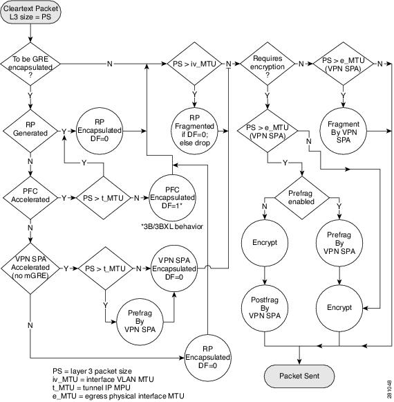
Fragmentation will be performed as follows:
•![]() If any packets to be sent to the IPsec VPN SPA exceed the MTU of the interface VLAN, the RP will perform prefragmentation before sending the packets to the IPsec VPN SPA.
If any packets to be sent to the IPsec VPN SPA exceed the MTU of the interface VLAN, the RP will perform prefragmentation before sending the packets to the IPsec VPN SPA.
•![]() If packets to be GRE encapsulated exceed the IP MTU of the GRE tunnel:
If packets to be GRE encapsulated exceed the IP MTU of the GRE tunnel:
–![]() The RP will perform prefragmentation when the tunnel is not taken over by the IPsec VPN SPA.
The RP will perform prefragmentation when the tunnel is not taken over by the IPsec VPN SPA.
–![]() The IPsec VPN SPA will perform prefragmentation when the tunnel is taken over by the IPsec VPN SPA.
The IPsec VPN SPA will perform prefragmentation when the tunnel is taken over by the IPsec VPN SPA.
•![]() If packets to be encrypted will exceed the MTU of the physical egress interface:
If packets to be encrypted will exceed the MTU of the physical egress interface:
–![]() If IPsec prefragmentation is enabled, the IPsec VPN SPA will perform prefragmentation of the packets. The IPsec VPN SPA will not perform post-fragmentation.
If IPsec prefragmentation is enabled, the IPsec VPN SPA will perform prefragmentation of the packets. The IPsec VPN SPA will not perform post-fragmentation.
–![]() If IPsec prefragmentation is disabled, the IPsec VPN SPA will perform post-fragmentation of the encrypted packets. The IPsec VPN SPA will not perform prefragmentation.
If IPsec prefragmentation is disabled, the IPsec VPN SPA will perform post-fragmentation of the encrypted packets. The IPsec VPN SPA will not perform prefragmentation.
•![]() If unencrypted egress packets will exceed the MTU of the physical egress interface, the IPsec VPN SPA will perform fragmentation of the packets.
If unencrypted egress packets will exceed the MTU of the physical egress interface, the IPsec VPN SPA will perform fragmentation of the packets.
Figure 23-1 shows the fragmentation process for packets in crypto-connect mode.
Figure 23-1 Fragmentation of Packets in Crypto-Connect Mode
Fragmentation of IPsec (Using Crypto Maps) Packets in VRF Mode
The following are the relevant MTU settings for fragmentation of IPsec traffic in VRF mode:
•![]() The MTU of the interface VLAN.
The MTU of the interface VLAN.
Prefragmentation by the RP will be based on this MTU.
•![]() The MTU of the physical egress interface.
The MTU of the physical egress interface.
Pre- and post-fragmentation by the IPsec VPN SPA will be based on this MTU.
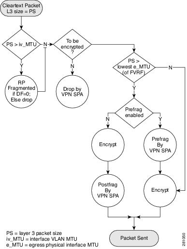
Fragmentation will be performed as follows:
•![]() If packets exceed the MTU of the interface VLAN, the RP will perform prefragmentation.
If packets exceed the MTU of the interface VLAN, the RP will perform prefragmentation.
•![]() If encrypted egress packets will exceed the lowest MTU of any physical egress interface on the FVRF:
If encrypted egress packets will exceed the lowest MTU of any physical egress interface on the FVRF:
–![]() If IPsec prefragmentation is enabled, the IPsec VPN SPA will perform prefragmentation of the packets. The IPsec VPN SPA will not perform post-fragmentation.
If IPsec prefragmentation is enabled, the IPsec VPN SPA will perform prefragmentation of the packets. The IPsec VPN SPA will not perform post-fragmentation.
–![]() If IPsec prefragmentation is disabled, the IPsec VPN SPA will perform post-fragmentation of the encrypted packets. The IPsec VPN SPA will not perform prefragmentation.
If IPsec prefragmentation is disabled, the IPsec VPN SPA will perform post-fragmentation of the encrypted packets. The IPsec VPN SPA will not perform prefragmentation.
The fragmentation process for IPsec packets in VRF mode is shown in Figure 23-2.
Figure 23-2 Fragmentation of IPsec Packets in VRF Mode
Fragmentation of GRE Packets with Tunnel Protection in VRF Mode
The following are the relevant MTU settings for fragmentation of GRE traffic with tunnel protection in VRF mode:
•![]() The IP MTU of the GRE tunnel.
The IP MTU of the GRE tunnel.
Prefragmentation will be based on this MTU.
•![]() The lowest MTU of any physical egress interface on the FVRF.
The lowest MTU of any physical egress interface on the FVRF.
Pre- and post-fragmentation by the IPsec VPN SPA will be based on this MTU.
Fragmentation will be performed as follows:
•![]() If packets to be encapsulated exceed the IP MTU of the GRE tunnel:
If packets to be encapsulated exceed the IP MTU of the GRE tunnel:
–![]() The RP will perform prefragmentation when the tunnel is not taken over by the IPsec VPN SPA.
The RP will perform prefragmentation when the tunnel is not taken over by the IPsec VPN SPA.
–![]() The IPsec VPN SPA will perform prefragmentation when the tunnel is taken over by the IPsec VPN SPA.
The IPsec VPN SPA will perform prefragmentation when the tunnel is taken over by the IPsec VPN SPA.
•![]() If encrypted GRE-encapsulated packets will exceed the lowest MTU of any physical egress interface on the FVRF:
If encrypted GRE-encapsulated packets will exceed the lowest MTU of any physical egress interface on the FVRF:
–![]() If IPsec prefragmentation is enabled, the IPsec VPN SPA will perform prefragmentation of the GRE-encapsulated packets. The IPsec VPN SPA will not perform post-fragmentation.
If IPsec prefragmentation is enabled, the IPsec VPN SPA will perform prefragmentation of the GRE-encapsulated packets. The IPsec VPN SPA will not perform post-fragmentation.
–![]() If IPsec prefragmentation is disabled, the IPsec VPN SPA will perform post-fragmentation of the encrypted GRE-encapsulated packets. The IPsec VPN SPA will not perform prefragmentation.
If IPsec prefragmentation is disabled, the IPsec VPN SPA will perform post-fragmentation of the encrypted GRE-encapsulated packets. The IPsec VPN SPA will not perform prefragmentation.
The fragmentation process for GRE packets with tunnel protection in VRF mode is shown in Figure 23-3.
Figure 23-3 Fragmentation of GRE Packets with Tunnel Protection in VRF Mode

Fragmentation in VTIs
The following are the relevant MTU settings for fragmentation of VTI packets:
•![]() The IP MTU of the VTI tunnel interface.
The IP MTU of the VTI tunnel interface.
Prefragmentation will be based on this MTU.
Note ![]() We recommend that the IP MTU of the VTI tunnel interface be left at its default value. If you change it, be sure that it does not exceed the MTU of the physical egress interface minus the IPsec overhead.
We recommend that the IP MTU of the VTI tunnel interface be left at its default value. If you change it, be sure that it does not exceed the MTU of the physical egress interface minus the IPsec overhead.
•![]() The MTU of the physical egress interface.
The MTU of the physical egress interface.
Post-fragmentation by the IPsec VPN SPA will be based on this MTU.
Fragmentation will be performed as follows:
•![]() If IPsec prefragmentation is enabled, the IPsec VPN SPA will perform prefragmentation of packets that exceed the IP MTU of the VTI tunnel interface. The IPsec VPN SPA will not perform post-fragmentation.
If IPsec prefragmentation is enabled, the IPsec VPN SPA will perform prefragmentation of packets that exceed the IP MTU of the VTI tunnel interface. The IPsec VPN SPA will not perform post-fragmentation.
Note ![]() The RP will perform post-fragmentation of packets that exceed the MTU of the egress interface. This is considered a misconfiguration.
The RP will perform post-fragmentation of packets that exceed the MTU of the egress interface. This is considered a misconfiguration.
•![]() If IPsec prefragmentation is disabled, the IPsec VPN SPA will perform post-fragmentation of packets that exceed the MTU of the egress interface. The IPsec VPN SPA will not perform prefragmentation.
If IPsec prefragmentation is disabled, the IPsec VPN SPA will perform post-fragmentation of packets that exceed the MTU of the egress interface. The IPsec VPN SPA will not perform prefragmentation.
The fragmentation process for VTI packets is shown in Figure 23-4.
Figure 23-4 Fragmentation of VTI Packets

Fragmentation in Cisco IOS Release 12.2(33)SXI and Later Releases
The fragmentation in Cisco IOS Release 12.2(33)SXI and later releases differs from earlier fragmentation in these significant ways:
•![]() The IPsec VPN SPA will perform only a single fragmentation operation, either prefragmentation or postfragmentation, but not both.
The IPsec VPN SPA will perform only a single fragmentation operation, either prefragmentation or postfragmentation, but not both.
•![]() Fragmentation is based on the IP MTU of the tunnel or of the crypto interface VLAN, not the egress interface.
Fragmentation is based on the IP MTU of the tunnel or of the crypto interface VLAN, not the egress interface.
•![]() Path MTU discovery (PMTUD) is supported in both crypto-connect and VRF modes.
Path MTU discovery (PMTUD) is supported in both crypto-connect and VRF modes.
•![]() The ip tcp adjust-mss command is supported in all modes.
The ip tcp adjust-mss command is supported in all modes.
As in earlier releases, the fragmentation process differs depending on the IPsec VPN mode and whether GRE or VTI is used. The process is described in the following sections:
•![]() Overview of the Fragmentation Process
Overview of the Fragmentation Process
•![]() Fragmentation of IPsec Packets in Crypto-Connect Mode
Fragmentation of IPsec Packets in Crypto-Connect Mode
•![]() Fragmentation of GRE Packets in Crypto-Connect Mode
Fragmentation of GRE Packets in Crypto-Connect Mode
•![]() Fragmentation of IPsec Packets in VRF Mode
Fragmentation of IPsec Packets in VRF Mode
•![]() Fragmentation of GRE Packets in VRF Mode
Fragmentation of GRE Packets in VRF Mode
•![]() Fragmentation of IPsec Packets Using VTI
Fragmentation of IPsec Packets Using VTI
Overview of the Fragmentation Process
Figure 23-5 shows the fragmentation process for IPsec packets in all VPN modes.
Figure 23-5 Fragmentation of IPsec Packets in All VPN Modes

These notes apply to the fragmentation process described in Figure 23-5:
•![]() The fragmentation process applies only when the DF (Don't Fragment) bit is not set for cleartext packets entering the flowchart. If a packet requires fragmentation and the DF bit is set, the packet will be dropped.
The fragmentation process applies only when the DF (Don't Fragment) bit is not set for cleartext packets entering the flowchart. If a packet requires fragmentation and the DF bit is set, the packet will be dropped.
•![]() VTI encapsulation is always taken over by the IPsec VPN SPA.
VTI encapsulation is always taken over by the IPsec VPN SPA.
•![]() GRE encapsulation of RP-generated packets is never taken over by the IPsec VPN SPA.
GRE encapsulation of RP-generated packets is never taken over by the IPsec VPN SPA.
•![]() GRE encapsulation of mGRE packets is never taken over by the IPsec VPN SPA.
GRE encapsulation of mGRE packets is never taken over by the IPsec VPN SPA.
Fragmentation of IPsec Packets in Crypto-Connect Mode
For fragmentation of packets in crypto-connect mode, the following are the MTU setting requirements and recommendations:
•![]() The configured IP MTU of the interface VLAN
The configured IP MTU of the interface VLAN
–![]() Prefragmentation of traffic by the IPsec VPN SPA is based on this MTU.
Prefragmentation of traffic by the IPsec VPN SPA is based on this MTU.
–![]() You must configure this MTU to be less than or equal to the minimum MTU of the physical egress interfaces configured on the port VLAN, or packets will be dropped.
You must configure this MTU to be less than or equal to the minimum MTU of the physical egress interfaces configured on the port VLAN, or packets will be dropped.
•![]() The configured MTU of the LAN interface
The configured MTU of the LAN interface
–![]() To avoid fragmentation by the RP, we recommend that you configure the MTU of the LAN interface to be less than or equal to the configured IP MTU of the interface VLAN.
To avoid fragmentation by the RP, we recommend that you configure the MTU of the LAN interface to be less than or equal to the configured IP MTU of the interface VLAN.
In the following example, a 1500-byte cleartext packet will not be fragmented by the RP, because it is within the MTU of the interface VLAN. The cleartext packet will be fragmented by the IPsec VPN SPA, because the IPsec overhead would cause the encrypted packet to exceed the MTU of the interface VLAN.
A 1600-byte cleartext packet will first be fragmented by the RP, because the packet exceeds the MTU of the interface VLAN. The packet will then be fragmented again by the IPsec VPN SPA, because the IPsec overhead added by the encryption process would cause the encrypted packet to exceed the MTU of the interface VLAN.
interface GigabitEthernet1/1
! switch inside port
mtu 9216
ip address 13.0.0.1 255.255.255.0
!
interface GigabitEthernet1/2
! switch outside port
! mtu 1500 by default
switchport
switchport access vlan 502
switchport mode access
!
interface Vlan2
! interface vlan
! mtu 1500 by default
ip address 11.0.0.2 255.255.255.0
crypto map testtag
crypto engine slot 4/0
!
interface Vlan502
! port vlan
no ip address
crypto connect vlan 2
!
Fragmentation of GRE Packets in Crypto-Connect Mode
For fragmentation of packets in crypto-connect mode, the following are the MTU setting requirements and recommendations:
•![]() The configured IP MTU of the crypto interface VLAN
The configured IP MTU of the crypto interface VLAN
–![]() You must configure this MTU to be less than or equal to the minimum MTU of the physical egress interfaces configured on the port VLAN, or packets will be dropped.
You must configure this MTU to be less than or equal to the minimum MTU of the physical egress interfaces configured on the port VLAN, or packets will be dropped.
•![]() The configured MTU of the LAN interface
The configured MTU of the LAN interface
–![]() To avoid fragmentation by the RP, we recommend that you configure the MTU of the LAN interface to be less than or equal to the configured IP MTU of the crypto interface VLAN.
To avoid fragmentation by the RP, we recommend that you configure the MTU of the LAN interface to be less than or equal to the configured IP MTU of the crypto interface VLAN.
•![]() The configured IP MTU of the GRE tunnel interface
The configured IP MTU of the GRE tunnel interface
–![]() Prefragmentation of traffic by the IPsec VPN SPA is based on this MTU.
Prefragmentation of traffic by the IPsec VPN SPA is based on this MTU.
–![]() You must set this MTU so that IPsec-encrypted GRE packets will not exceed the IP MTU of the crypto interface VLAN, or packets will be dropped. This requirement applies regardless of whether the GRE tunnel is taken over by the IPsec VPN SPA.
You must set this MTU so that IPsec-encrypted GRE packets will not exceed the IP MTU of the crypto interface VLAN, or packets will be dropped. This requirement applies regardless of whether the GRE tunnel is taken over by the IPsec VPN SPA.
In the following example, if the tunnel is taken over by the IPsec VPN SPA, a 1600-byte cleartext packet will be fragmented by the IPsec VPN SPA, because the packet exceeds the IP MTU of the tunnel interface. The fragmented packet will then be GRE-encapsulated and IPsec-encrypted by the IPsec VPN SPA.
If the tunnel is not taken over by the IPsec VPN SPA, a 1600-byte cleartext packet will be fragmented by the RP, because the packet exceeds the IP MTU of the tunnel interface. The fragmented packet will then be GRE-encapsulated by the PFC and IPsec-encrypted by the IPsec VPN SPA.
interface Tunnel1
ip mtu 1400
ip address 1.0.0.1 255.255.255.0
tunnel source Vlan2
tunnel destination 11.0.0.2
!
interface GigabitEthernet1/1
! switch inside port
mtu 9216
ip address 12.0.0.1 255.255.255.0
!
interface GigabitEthernet1/2
! switch outside port
! mtu 1500 by default
switchport
switchport access vlan 502
switchport mode access
!
interface Vlan2
! mtu 1500 by default
ip address 11.0.0.1 255.255.255.0
no mop enabled
crypto map testtag
crypto engine slot 4/0
!
interface Vlan502
no ip address
crypto connect vlan 2
!
Fragmentation of IPsec Packets in VRF Mode
For fragmentation of packets in VRF mode, the following are the MTU setting requirements and recommendations:
•![]() The MTU of the crypto interface VLAN.
The MTU of the crypto interface VLAN.
–![]() Prefragmentation by the IPsec VPN SPA will be based on this MTU.
Prefragmentation by the IPsec VPN SPA will be based on this MTU.
–![]() You must configure this MTU to be less than or equal to the minimum MTU of the physical egress interfaces, or packets will be dropped.
You must configure this MTU to be less than or equal to the minimum MTU of the physical egress interfaces, or packets will be dropped.
•![]() The configured MTU of the LAN interface
The configured MTU of the LAN interface
–![]() To avoid fragmentation by the RP, we recommend that you configure the MTU of the LAN interface to be less than or equal to the configured IP MTU of the crypto interface VLAN.
To avoid fragmentation by the RP, we recommend that you configure the MTU of the LAN interface to be less than or equal to the configured IP MTU of the crypto interface VLAN.
In the following example, a 1500-byte cleartext packet will not be fragmented by the RP, because it is within the MTU of the interface VLAN. The cleartext packet will be fragmented by the IPsec VPN SPA, because the IPsec overhead would cause the encrypted packet to exceed the MTU of the interface VLAN.
A 1600-byte cleartext packet will first be fragmented by the RP, because the packet exceeds the MTU of the interface VLAN. The packet will then be fragmented again by the IPsec VPN SPA, because the IPsec overhead added by the encryption process would cause the encrypted packet to exceed the MTU of the interface VLAN.
interface GigabitEthernet1/1
! switch inside port
mtu 9216
ip vrf forwarding ivrf
ip address 12.0.0.1 255.255.255.0
!
!
interface GigabitEthernet1/2
! switch outside port
! mtu 1500 by default
ip address 11.0.0.1 255.255.255.0
crypto engine slot 4/0 outside
!
interface Vlan2
! mtu 1500 by default
ip vrf forwarding ivrf
ip address 13.0.0.252 255.255.255.0
crypto map testtag
crypto engine slot 4/0 inside
!
Fragmentation of GRE Packets in VRF Mode
For fragmentation of packets in VRF mode, the following are the MTU setting requirements and recommendations:
•![]() The MTU of the crypto interface VLAN.
The MTU of the crypto interface VLAN.
–![]() You must configure this MTU to be less than or equal to the minimum MTU of the physical egress interfaces configured on the port VLAN, or packets will be dropped.
You must configure this MTU to be less than or equal to the minimum MTU of the physical egress interfaces configured on the port VLAN, or packets will be dropped.
•![]() The configured MTU of the LAN interface
The configured MTU of the LAN interface
–![]() To avoid fragmentation by the RP, we recommend that you configure the MTU of the LAN interface to be less than or equal to the configured IP MTU of the crypto interface VLAN.
To avoid fragmentation by the RP, we recommend that you configure the MTU of the LAN interface to be less than or equal to the configured IP MTU of the crypto interface VLAN.
•![]() The configured IP MTU of the GRE tunnel interface
The configured IP MTU of the GRE tunnel interface
–![]() Prefragmentation by the IPsec VPN SPA will be based on this MTU.
Prefragmentation by the IPsec VPN SPA will be based on this MTU.
–![]() You must set this MTU so that IPsec-encrypted GRE packets will not exceed the minimum MTU of the physical egress interfaces, or packets will be dropped. This requirement applies regardless of whether the GRE tunnel is taken over by the IPsec VPN SPA.
You must set this MTU so that IPsec-encrypted GRE packets will not exceed the minimum MTU of the physical egress interfaces, or packets will be dropped. This requirement applies regardless of whether the GRE tunnel is taken over by the IPsec VPN SPA.
In the following example, if the tunnel is taken over by the IPsec VPN SPA, a 1600-byte cleartext packet will be fragmented by the IPsec VPN SPA, because the packet exceeds the IP MTU of the tunnel interface. The fragmented packet will then be GRE-encapsulated and IPsec-encrypted by the IPsec VPN SPA.
If the tunnel is not taken over by the IPsec VPN SPA, a 1600-byte cleartext packet will be fragmented by the RP, because the packet exceeds the IP MTU of the tunnel interface. The fragmented packet will then be GRE-encapsulated by the PFC and IPsec-encrypted by the IPsec VPN SPA.
interface Tunnel1
ip mtu 1400
ip vrf forwarding coke
ip address 10.1.1.254 255.255.255.0
tunnel source 172.1.1.1
tunnel destination 100.1.1.1
tunnel protection ipsec profile tp
crypto engine slot 4/0 inside
!
interface GigabitEthernet6/1
! switch outside port
! mtu 1500 by default
ip address 172.1.1.1 255.255.255.0
crypto engine slot 4/0 outside
!
interface FastEthernet7/13
! switch inside port
mtu 9216
ip vrf forwarding coke
ip address 13.1.1.2 255.255.255.0
!
Fragmentation of IPsec Packets Using VTI
The following are the relevant MTU settings for fragmentation of sVTI packets:
•![]() The IP MTU of the VTI tunnel interface.
The IP MTU of the VTI tunnel interface.
–![]() Prefragmentation by the IPsec VPN SPA will be based on this MTU.
Prefragmentation by the IPsec VPN SPA will be based on this MTU.
–![]() Configuring this MTU is unnecessary because it is automatically adjusted to accommodate the IPsec overhead.
Configuring this MTU is unnecessary because it is automatically adjusted to accommodate the IPsec overhead.
Note ![]() We recommend that the IP MTU of the VTI tunnel interface be left at its default value. If you change it, be sure that it does not exceed the MTU of the physical egress interface minus the IPsec overhead.
We recommend that the IP MTU of the VTI tunnel interface be left at its default value. If you change it, be sure that it does not exceed the MTU of the physical egress interface minus the IPsec overhead.
The fragmentation behavior using VTI is the same as the behavior shown in the "Fragmentation of GRE Packets in VRF Mode" section for the case in which the tunnel is taken over by the IPsec VPN SPA.
Configuring IPsec Prefragmentation
IPsec prefragmentation can be configured globally or at the interface level. By default, IPsec prefragmentation is enabled globally. Enabling or disabling IPsec prefragmentation at the interface will override the global configuration.
IPsec Prefragmentation Configuration Guidelines
Note ![]() In Cisco IOS Release 12.2(33)SXI and later releases, tunnels support only IPsec prefragmentation; postfragmentation is not supported. The guidelines in this section apply only to an interface to which a crypto map is applied.
In Cisco IOS Release 12.2(33)SXI and later releases, tunnels support only IPsec prefragmentation; postfragmentation is not supported. The guidelines in this section apply only to an interface to which a crypto map is applied.
When configuring IPsec prefragmentation, follow these guidelines:
•![]() To configure IPsec prefragmentation at the interface level, apply it on the interface to which the crypto map is applied.
To configure IPsec prefragmentation at the interface level, apply it on the interface to which the crypto map is applied.
•![]() If an IPsec peer is experiencing high CPU utilization with large packet flows, verify that IPsec prefragmentation is enabled (the peer may be reassembling large packets).
If an IPsec peer is experiencing high CPU utilization with large packet flows, verify that IPsec prefragmentation is enabled (the peer may be reassembling large packets).
•![]() IPsec prefragmentation for IPsec VPNs operates in IPsec tunnel mode. It does not apply in IPsec transport mode.
IPsec prefragmentation for IPsec VPNs operates in IPsec tunnel mode. It does not apply in IPsec transport mode.
•![]() IPsec prefragmentation for IPsec VPNs functionality depends on the crypto ipsec df-bit configuration of the interface to which the crypto map is applied, and on the incoming packet "do not fragment" (DF) bit state. For general information about IPsec prefragmentation, see the following URL:
IPsec prefragmentation for IPsec VPNs functionality depends on the crypto ipsec df-bit configuration of the interface to which the crypto map is applied, and on the incoming packet "do not fragment" (DF) bit state. For general information about IPsec prefragmentation, see the following URL:
http://www.cisco.com/en/US/docs/ios/12_2t/12_2t13/feature/guide/ftprefrg.html
•![]() GRE+IP encapsulation adds 24 bytes to the packet size. When configuring for prefragmentation based on anticipated GRE overhead, use this value.
GRE+IP encapsulation adds 24 bytes to the packet size. When configuring for prefragmentation based on anticipated GRE overhead, use this value.
•![]() IPsec encryption adds a number of bytes to the packet size depending on the configured IPsec transform set. When configuring for prefragmentation based on anticipated IPsec overhead, use the following table of worst-case IPsec overhead bytes for various IPsec transform sets:
IPsec encryption adds a number of bytes to the packet size depending on the configured IPsec transform set. When configuring for prefragmentation based on anticipated IPsec overhead, use the following table of worst-case IPsec overhead bytes for various IPsec transform sets:
Configuring IPsec Prefragmentation Globally
IPsec prefragmentation is globally enabled by default. To enable or disable prefragmentation for IPsec VPNs at the global level, perform this task beginning in global configuration mode:
Configuring IPsec Prefragmentation at the Interface
IPsec prefragmentation is globally enabled by default. To enable or disable prefragmentation for IPsec VPNs at the interface level, perform this task beginning in interface configuration mode for the interface to which the crypto map is attached:
Note ![]() Enabling or disabling IPsec prefragmentation at the interface will override the global configuration.
Enabling or disabling IPsec prefragmentation at the interface will override the global configuration.
Verifying the IPsec Prefragmentation Configuration
To verify that IPsec prefragmentation is enabled, consult the interface statistics on the encrypting switch and the decrypting switch. If fragmentation occurs on the encrypting switch, and no reassembly occurs on the decrypting switch, fragmentation is occurring before encryption, which means that the packets are not being reassembled before decryption and the feature is enabled.
To verify that the IPsec prefragmentation feature is enabled, enter the show running-configuration command on the encrypting switch. If the feature is enabled, no fragmentation feature will appear in the command output:
Router# show running-configuration
crypto isakmp policy 10
authentication pre-share
crypto isakmp key abcd123 address 25.0.0.7
crypto ipsec transform-set fooprime esp-3des esp-sha-hmac
!!! the postfragmentation feature appears here if IPsec prefragmentation is disabled
crypto map bar 10 ipsec-isakmp
set peer 25.0.0.7
set transform-set fooprime
match address 102
If IPsec prefragmentation has been disabled, the postfragmentation feature will appear in the command output:
Router# show running-configuration
crypto isakmp policy 10
authentication pre-share
crypto isakmp key abcd123 address 25.0.0.7
crypto ipsec transform-set fooprime esp-3des esp-sha-hmac
crypto ipsec fragmentation after-encryption
crypto map bar 10 ipsec-isakmp
set peer 25.0.0.7
set transform-set fooprime
match address 102
To display the configuration of the encrypting switch interface VLAN, enter the show running-configuration interface command. If the IPsec prefragmentation feature is enabled, a prefragmentation statement will appear in the command output:
Router# show running-configuration interface vlan2
interface Vlan2
ip address 15.0.0.2 255.255.255.0
crypto map testtag
crypto engine slot 1/0
crypto ipsec fragmentation before-encryption
If the IPsec prefragmentation feature has been disabled at the interface VLAN, a postfragmentation statement will appear in the command output:
Router# show running-configuration interface vlan2
interface Vlan2
ip address 15.0.0.2 255.255.255.0
crypto map testtag
crypto engine slot 1/0
crypto ipsec fragmentation after-encryption end
Configuring MTU Settings
The Cisco IOS software allows the configuration of the Layer 3 maximum transmission unit (MTU) of interfaces and VLANs. You should ensure that all MTU values are consistent to avoid unnecessary fragmentation of packets.
Note ![]() When configuring MTU, note that the ip mtu command applies only to IP protocol traffic. Other Layer 3 protocol traffic will observe the MTU configured by the mtu command.
When configuring MTU, note that the ip mtu command applies only to IP protocol traffic. Other Layer 3 protocol traffic will observe the MTU configured by the mtu command.
MTU Settings Configuration Guidelines and Restrictions
When configuring MTU settings for an IPsec VPN SPA, follow these guidelines and note these restrictions:
•![]() In Cisco IOS Release 12.2(33)SXH and earlier releases, the MTU value used by the IPsec VPN SPA for fragmentation decisions is based on the MTU value of the secure port as follows:
In Cisco IOS Release 12.2(33)SXH and earlier releases, the MTU value used by the IPsec VPN SPA for fragmentation decisions is based on the MTU value of the secure port as follows:
–![]() Routed ports—Use the MTU value of their associated secure port.
Routed ports—Use the MTU value of their associated secure port.
–![]() Access ports—Use the MTU value of the secure port associated with their interface VLAN.
Access ports—Use the MTU value of the secure port associated with their interface VLAN.
–![]() Trunk ports—Use the MTU value of the secure port associated with their interface VLAN.
Trunk ports—Use the MTU value of the secure port associated with their interface VLAN.
•![]() In Cisco IOS Release 12.2(33)SXI and later releases, the MTU value used by the IPsec VPN SPA for fragmentation decisions is based on the IP MTU of the tunnel or of the crypto interface VLAN, not the egress interface. For information on the recommended MTU settings, see the "Fragmentation in Cisco IOS Release 12.2(33)SXI and Later Releases" section.
In Cisco IOS Release 12.2(33)SXI and later releases, the MTU value used by the IPsec VPN SPA for fragmentation decisions is based on the IP MTU of the tunnel or of the crypto interface VLAN, not the egress interface. For information on the recommended MTU settings, see the "Fragmentation in Cisco IOS Release 12.2(33)SXI and Later Releases" section.
•![]() If you have GRE tunneling configured, see the "Fragmentation in Cisco IOS Release 12.2(33)SXH and Earlier Releases" section or the "Fragmentation in Cisco IOS Release 12.2(33)SXI and Later Releases" section for information on the recommended MTU settings.
If you have GRE tunneling configured, see the "Fragmentation in Cisco IOS Release 12.2(33)SXH and Earlier Releases" section or the "Fragmentation in Cisco IOS Release 12.2(33)SXI and Later Releases" section for information on the recommended MTU settings.
Note ![]() For additional information on fragmentation of packets, see the "Configuring IPsec Prefragmentation" section.
For additional information on fragmentation of packets, see the "Configuring IPsec Prefragmentation" section.
Changing the Physical Egress Interface MTU
You can configure either the Layer 3 MTU or the IP MTU of the physical egress interface. To change the MTU value on a physical egress interface, perform this task beginning in global configuration mode:
|
|
|
|
|---|---|---|
Step 1 |
Router(config)# interface type1 slot/port |
Enters interface configuration mode for the interface. |
Step 2 |
Router(config-if)# mtu bytes |
Configures the maximum transmission unit (MTU) size for the interface. • |
1 type = fastethernet, gigabitethernet, or tengigabitethernet |
Changing the Tunnel Interface IP MTU
You can configure the IP MTU of the tunnel interface, but you cannot configure the Layer 3 MTU. To change the IP MTU value on a tunnel, perform this task beginning in global configuration mode:
Changing the Interface VLAN MTU
You can configure the Layer 3 MTU of the interface VLAN. To change the MTU value on an interface VLAN, perform this task beginning in global configuration mode:
Verifying the MTU Size
To verify the MTU size for an interface, enter the show interface command or the show ip interface command, as shown in the following examples:
To display the MTU value for a secure port, enter the show interface command:
Router# show interface g1/1
GigabitEthernet1/1 is up, line protocol is up (connected)
Hardware is C6k 1000Mb 802.3, address is 000a.8ad8.1c4a (bia 000a.8ad8.1c4a)
MTU 9216 bytes, BW 1000000 Kbit, DLY 10 usec,
reliability 255/255, txload 1/255, rxload 1/255
...
To display the MTU size for an interface VLAN, enter the show interface command.
Router# show interface vlan2
Vlan2 is up, line protocol is up
Hardware is EtherSVI, address is 000e.39ad.e700 (bia 000e.39ad.e700)
Internet address is 192.168.1.1/16
MTU 1000 bytes, BW 1000000 Kbit, DLY 10 usec,
reliability 255/255, txload 1/255, rxload 1/255
Encapsulation ARPA, loopback not set
...
To display the IP MTU value for a GRE tunnel, enter the show ip interface command:
Router# show ip interface tunnel 2
Tunnel2 is up, line protocol is up
Internet address is 11.1.0.2/16
Broadcast address is 255.255.255.255
Address determined by non-volatile memory
MTU is 1450 bytes
...
Configuration Examples
The following sections provide examples of IPsec prefragmentation configurations using commands at the level of Cisco IOS Release 12.2(33)SXI:
•![]() Crypto-Connect Mode IPsec Prefragmentation Configuration Example
Crypto-Connect Mode IPsec Prefragmentation Configuration Example
•![]() VRF Mode with GRE using Tunnel Protection IPsec Prefragmentation Configuration Example
VRF Mode with GRE using Tunnel Protection IPsec Prefragmentation Configuration Example
Crypto-Connect Mode IPsec Prefragmentation Configuration Example
The following example shows an IPsec prefragmentation configuration using crypto-connect mode:
!
hostname router-1
!
vlan 2,502
!
crypto isakmp policy 1
encr 3des
authentication pre-share
crypto isakmp key 12345 address 11.0.0.1
!
!
crypto ipsec transform-set proposal1 esp-3des esp-md5-hmac
!
crypto map testtag 10 ipsec-isakmp
set peer 11.0.0.1
set transform-set proposal1
match address 101
!
!
interface GigabitEthernet1/1
!switch inside port
! mtu 1500 by default
ip address 13.0.0.1 255.255.255.0
!
interface GigabitEthernet1/2
!switch outside port
mtu 1000
switchport
switchport access vlan 502
switchport mode access
!
interface GigabitEthernet4/0/1
!IPsec VPN SPA inside port
switchport
switchport trunk encapsulation dot1q
switchport trunk allowed vlan 1,2,1002-1005
switchport mode trunk
mtu 9216
flowcontrol receive on
flowcontrol send off
spanning-tree portfast trunk
!
interface GigabitEthernet4/0/2
!IPsec VPN SPA outside port
switchport
switchport trunk encapsulation dot1q
switchport trunk allowed vlan 1,502,1002-1005
switchport mode trunk
mtu 9216
flowcontrol receive on
flowcontrol send off
spanning-tree portfast trunk
!
interface Vlan2
!interface vlan
mtu 1000
ip address 11.0.0.2 255.255.255.0
crypto map testtag
crypto engine slot 4/0
!
interface Vlan502
!port vlan
no ip address
crypto connect vlan 2
!
ip classless
ip route 12.0.0.0 255.0.0.0 11.0.0.1
!
access-list 101 permit ip host 13.0.0.2 host 12.0.0.2
!
end
VRF Mode with GRE using Tunnel Protection IPsec Prefragmentation Configuration Example
The following example shows an IPsec prefragmentation configuration using VRF mode with GRE and tunnel protection:
!
hostname router-1
!
ip vrf coke
rd 1000:1
route-target export 1000:1
route-target import 1000:1
!
crypto keyring key1
pre-shared-key address 100.1.1.1 key happy-eddie
!
crypto isakmp policy 1
authentication pre-share
crypto isakmp profile prof1
keyring key1
match identity address 100.1.1.1 255.255.255.255
!
crypto ipsec transform-set TR esp-des esp-md5-hmac
mode transport
!
crypto ipsec profile tp
set transform-set TR
set isakmp-profile prof1
!
!
crypto engine mode vrf
!
interface Tunnel1
ip mtu 1400
ip vrf forwarding coke
ip address 10.1.1.254 255.255.255.0
tunnel source 172.1.1.1
tunnel destination 100.1.1.1
tunnel protection ipsec profile tp
crypto engine slot 4/0 inside
!
interface GigabitEthernet4/0/1
!IPsec VPN SPA inside port
flowcontrol receive on
flowcontrol send off
switchport
switchport trunk encapsulation dot1q
switchport trunk allowed vlan 1,1002-1005
switchport mode trunk
cdp enable
spanning-tree portfast trunk
!
interface GigabitEthernet4/0/2
!IPsec VPN SPA outside port
no ip address
flowcontrol receive on
flowcontrol send off
switchport
switchport trunk encapsulation dot1q
switchport trunk allowed vlan 1,1002-1005
switchport mode trunk
cdp enable
spanning-tree portfast trunk
!
interface GigabitEthernet6/1
! mtu 1500 by default
ip address 172.1.1.1 255.255.255.0
crypto engine slot 4/0 outside
!
interface FastEthernet7/13
ip vrf forwarding coke
ip address 13.1.1.2 255.255.255.0
!
ip route 100.1.1.1 255.255.255.255 Tunnel1
end
 Feedback