- Index
- Preface
- Using Cisco IOS Software
- SIP, SSC, and SPA Product Overview
-
- Overview of the IPsec VPN SPA
- Configuring VPNs in Crypto-Connect Mode
- Configuring VPNs in VRF Mode
- Configuring IPsec VPN Fragmentation and MTU
- Configuring IKE Features Using the IPsec VPN SPA
- Configuring Enhanced IPsec Features Using the IPsec VPN SPA
- Configuring PKI Using the IPsec VPN SPA
- Configuring Advanced VPNs Using the IPsec VPN SPA
- Configuring Duplicate Hardware and IPsec Failover Using the IPsec VPN SPA
- Configuring Monitoring and Accounting for the IPsec VPN SPA
- Troubleshooting the IPsec VPN SPA
- Glossary
- Overview of Advanced VPNs
- Configuring DMVPN
- DMVPN Configuration Guidelines and Restrictions
- DMVPN Prerequisites
- Configuring an IPsec Profile
- Configuring the Hub for DMVPN in VRF Mode
- Configuring the Hub for DMVPN in Crypto-Connect Mode
- Configuring the Spoke for DMVPN in VRF Mode
- Configuring the Spoke for DMVPN in Crypto-Connect Mode
- Verifying the DMVPN Configuration
- Configuring the Easy VPN Server
- Configuring the Easy VPN Remote
- Configuring Easy VPN Remote RSA Signature Storage
- Configuration Examples
Configuring Advanced VPNs Using the IPsec VPN SPA
This chapter provides information about configuring advanced IPsec VPNs on the IPsec VPN SPA on the Catalyst 6500 Series switch. It includes the following sections:
•![]() Configuring the Easy VPN Server
Configuring the Easy VPN Server
•![]() Configuring the Easy VPN Remote
Configuring the Easy VPN Remote
•![]() Configuring Easy VPN Remote RSA Signature Storage
Configuring Easy VPN Remote RSA Signature Storage

Note ![]() The procedures in this chapter assume you have familiarity with security configuration concepts, such as VLANs, ISAKMP policies, preshared keys, transform sets, access control lists, and crypto maps. For more information about these and other security configuration concepts, refer to the following Cisco IOS documentation:
The procedures in this chapter assume you have familiarity with security configuration concepts, such as VLANs, ISAKMP policies, preshared keys, transform sets, access control lists, and crypto maps. For more information about these and other security configuration concepts, refer to the following Cisco IOS documentation:
Cisco IOS Security Configuration Guide, Release 12.2, at this URL:
http://www.cisco.com/en/US/docs/ios/12_2/security/configuration/guide/fsecur_c.html
Cisco IOS Security Command Reference, Release 12.2, at this URL:
http://www.cisco.com/en/US/docs/ios/12_2/security/command/reference/fsecur_r.html
For information about managing your system images and configuration files, refer to the Cisco IOS Configuration Fundamentals Configuration Guide, Release 12.2 and Cisco IOS Configuration Fundamentals Command Reference, Release 12.2 publications.
For additional information about the commands used in this chapter, see the the Catalyst 6500 Series Cisco IOS Command Reference, Release 12.2SX and the related Cisco IOS Release 12.2 software configuration guide and master index publications. For more information about accessing these publications, see the "Related Documentation" section on page xlv.

Tip ![]() To ensure a successful configuration of your VPN using the IPsec VPN SPA, read all of the configuration summaries and guidelines before you perform any configuration tasks.
To ensure a successful configuration of your VPN using the IPsec VPN SPA, read all of the configuration summaries and guidelines before you perform any configuration tasks.
Overview of Advanced VPNs
Configuring IP Security (IPsec) Virtual Private Networks (VPNs) in large, complicated networks can be quite complex. This chapter introduces Dynamic Multipoint VPN (DMVPN) and Easy VPN, two features that ease IPsec configuration in advanced environments.
Configuring DMVPN
The DMVPN feature allows users to better scale large and small IPsec VPNs by combining generic routing encapsulation (GRE) tunnels, IPsec encryption, and Next Hop Resolution Protocol (NHRP).
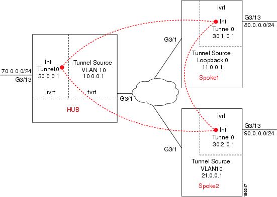
Figure 27-1 shows an example of a DMVPN configuration with a hub and two spokes.
Figure 27-1 DMVPN Configuration Example
DMVPN Configuration Guidelines and Restrictions
When configuring DMVPN, follow these guidelines and restrictions:
•![]() A tunnel key should not be configured. If a tunnel key is configured, neither the PFC3 nor the IPsec VPN SPA will take over the tunnel and the tunnel will be switched in software.
A tunnel key should not be configured. If a tunnel key is configured, neither the PFC3 nor the IPsec VPN SPA will take over the tunnel and the tunnel will be switched in software.
•![]() GRE tunnels in different Virtual Routing and Forwarding (VRF) instances cannot share the same tunnel source.
GRE tunnels in different Virtual Routing and Forwarding (VRF) instances cannot share the same tunnel source.
•![]() In non-VRF mode, multipoint GRE tunnels should not share the same tunnel source.
In non-VRF mode, multipoint GRE tunnels should not share the same tunnel source.
•![]() Multicast streaming is not supported across DMVPN on a Catalyst 6500 Series switch. Only multicast packets from a control plane such as routing protocols are supported.
Multicast streaming is not supported across DMVPN on a Catalyst 6500 Series switch. Only multicast packets from a control plane such as routing protocols are supported.
•![]() In a VRF-Aware DMVPN configuration, the mls mpls tunnel-recir command must be configured globally on the PE/hub if the CE/DMVPN spokes need to talk to other CEs across the MPLS cloud.
In a VRF-Aware DMVPN configuration, the mls mpls tunnel-recir command must be configured globally on the PE/hub if the CE/DMVPN spokes need to talk to other CEs across the MPLS cloud.
•![]() For the NAT-transparency aware enhancement to work with DMVPN, you must use IPsec transport mode on the transform set. Also, even though NAT-transparency (IKE and IPsec) can support two peers (IKE and IPsec) being translated to the same IP address (using the User Datagram Protocol [UDP] ports to differentiate them [this would be Peer Address Translation]), this functionality is not supported for DMVPN. All DMVPN spokes must have a unique IP address after they have been NAT translated. They can have the same IP address before they are NAT translated.
For the NAT-transparency aware enhancement to work with DMVPN, you must use IPsec transport mode on the transform set. Also, even though NAT-transparency (IKE and IPsec) can support two peers (IKE and IPsec) being translated to the same IP address (using the User Datagram Protocol [UDP] ports to differentiate them [this would be Peer Address Translation]), this functionality is not supported for DMVPN. All DMVPN spokes must have a unique IP address after they have been NAT translated. They can have the same IP address before they are NAT translated.
•![]() If you use the dynamic creation for spoke-to-spoke tunnels benefit of this feature, you must use IKE certificates or wildcard preshared keys for Internet Security Association and Key Management Protocol (ISAKMP) authentication.
If you use the dynamic creation for spoke-to-spoke tunnels benefit of this feature, you must use IKE certificates or wildcard preshared keys for Internet Security Association and Key Management Protocol (ISAKMP) authentication.
Note ![]() We recommend that you do not use wildcard preshared keys because access to the entire VPN is compromised if one spoke switch is compromised.
We recommend that you do not use wildcard preshared keys because access to the entire VPN is compromised if one spoke switch is compromised.
•![]() GRE tunnel keepalive (that is, the keepalive command under the GRE interface) is not supported on multipoint GRE tunnels
GRE tunnel keepalive (that is, the keepalive command under the GRE interface) is not supported on multipoint GRE tunnels
•![]() FVRF is not supported on a multipoint GRE (mGRE) tunnel configured on a DMVPN spoke. FVRF is supported on an mGRE tunnel configured on a DMVPN hub.
FVRF is not supported on a multipoint GRE (mGRE) tunnel configured on a DMVPN spoke. FVRF is supported on an mGRE tunnel configured on a DMVPN hub.
To enable mGRE and IPsec tunneling for hub and spoke switches, configure your mGRE tunnel for IPsec encryption using the following procedures:
•![]() Configuring the Hub for DMVPN in VRF Mode
Configuring the Hub for DMVPN in VRF Mode
•![]() Configuring the Hub for DMVPN in Crypto-Connect Mode
Configuring the Hub for DMVPN in Crypto-Connect Mode
•![]() Configuring the Spoke for DMVPN in VRF Mode
Configuring the Spoke for DMVPN in VRF Mode
•![]() Configuring the Spoke for DMVPN in Crypto-Connect Mode
Configuring the Spoke for DMVPN in Crypto-Connect Mode
•![]() Verifying the DMVPN Configuration
Verifying the DMVPN Configuration
For complete configuration information for DMVPN support, refer to this URL:
http://www.cisco.com/en/US/docs/ios/12_2t/12_2t13/feature/guide/ftgreips.html
DMVPN Prerequisites
Before configuring an IPsec profile, you must define a transform set by using the crypto ipsec transform-set command.
Configuring an IPsec Profile
The IPsec profile shares most of the same commands with the crypto map configuration, but only a subset of the commands are valid in an IPsec profile. Only commands that pertain to an IPsec policy can be issued under an IPsec profile; you cannot specify the IPsec peer address or the access control list (ACL) to match the packets that are to be encrypted.
To configure an IPsec profile, perform this task beginning in global configuration mode:
Configuring the Hub for DMVPN in VRF Mode
In VPN routing and forwarding instance (VRF) mode, to configure the hub switch for mGRE and IPsec integration (that is, to associate the tunnel with the IPsec profile configured in the previous procedure), perform this task beginning in global configuration mode:
Configuring the Hub for DMVPN in Crypto-Connect Mode
In crypto-connect mode, to configure the hub switch for mGRE and IPsec integration (that is, to associate the tunnel with the IPsec profile configured in the previous procedure), perform this task beginning in global configuration mode:
|
|
|
|
|---|---|---|
Step 1 |
Router(config)# interface tunnel tunnel-number |
Configures a tunnel interface and enters interface configuration mode. • |
Step 2 |
Router(config-if)# ip address ip-address mask [secondary] |
Sets a primary or secondary IP address for the tunnel interface. • • • |
Step 3 |
Router(config-if)# ip mtu bytes |
(Optional) Sets the maximum transmission unit (MTU) size, in bytes, of IP packets sent on an interface. • |
Step 4 |
Router(config-if)# ip nhrp authentication string |
(Optional) Configures the authentication string for an interface using the Next Hop Resolution Protocol (NHRP). • |
Step 5 |
Router(config-if)# ip nhrp map multicast dynamic |
Allows NHRP to automatically add spoke switches to the multicast NHRP mappings. |
Step 6 |
Router(config-if)# ip nhrp network-id number |
Enables NHRP on an interface. • |
Step 7 |
Router(config-if)# tunnel source {ip-address | type number} |
Sets source address for a tunnel interface. • • |
Step 8 |
Router(config-if)# tunnel mode gre multipoint |
Sets the encapsulation mode to mGRE for the tunnel interface. |
Step 9 |
Router(config-if)# tunnel protection ipsec profile name |
Associates a tunnel interface with an IPsec profile. • |
Step 10 |
Router(config-if)# crypto engine slot slot/subslot |
Assigns the specified crypto engine to the interface. • |
Step 11 |
Router(config)# interface vlan ifvlan |
Configures the DMVPN inside VLAN. |
Step 12 |
Router(config-if)# ip address address mask |
Sets a primary or secondary IP address for an interface. • • |
Step 13 |
Router(config-if)# crypto engine slot slot/subslot |
Assigns the specified crypto engine to the interface. • |
Step 14 |
Router(config-if)# interface type slot/subslot/port |
Configures the DMVPN physical egress interface. |
Step 15 |
Router(config-if)# no ip address |
Assigns no IP address to the interface. |
Step 16 |
Router(config-if)# crypto connect vlan ifvlan |
Connects the outside access port VLAN to the inside (crypto) interface VLAN and enters crypto-connect mode. • |
Configuring the Spoke for DMVPN in VRF Mode
In VRF mode, to configure spoke switches for mGRE and IPsec integration, perform this task beginning in global configuration mode:
Configuring the Spoke for DMVPN in Crypto-Connect Mode
In crypto-connect mode, to configure spoke switches for mGRE and IPsec integration, perform this task beginning in global configuration mode:
|
|
|
|
|---|---|---|
Step 1 |
Router(config)# interface tunnel tunnel-number |
Configures a tunnel interface and enters interface configuration mode • |
Step 2 |
Router(config-if)# ip address ip-address mask [secondary] |
Sets a primary or secondary IP address for the tunnel interface. • • • |
Step 3 |
Router(config-if)# ip mtu bytes |
(Optional) Sets the maximum transmission unit (MTU) size, in bytes, of IP packets sent on an interface. • |
Step 4 |
Router(config-if)# ip nhrp authentication string |
Configures the authentication string for an interface using NHRP. • |
Step 5 |
Router(config-if)# ip nhrp map hub-tunnel-ip-address hub-physical-ip-address |
Statically configures the IP-to-NonBroadcast MultiAccess (NBMA) address mapping of IP destinations connected to an NBMA network. • • |
Step 6 |
Router(config-if)# ip nhrp map multicast hub-physical-ip-address |
Enables the use of a dynamic routing protocol between the spoke and hub, and sends multicast packets to the hub switch. • |
Step 7 |
Router(config-if)# ip nhrp nhs hub-tunnel-ip-address |
Configures the hub switch as the NHRP next-hop server. • |
Step 8 |
Router(config-if)# ip nhrp network-id number |
Enables NHRP on an interface. • |
Step 9 |
Router(config-if)# tunnel source {ip-address | type number} |
Sets source address for a tunnel interface. • • |
Step 10 |
Router(config-if)# tunnel mode gre multipoint |
Sets the encapsulation mode to mGRE for the tunnel interface. Use this command if data traffic can use dynamic spoke-to-spoke traffic. |
Step 11 |
Router(config-if)# tunnel protection ipsec profile name |
Associates a tunnel interface with an IPsec profile. • |
Step 12 |
Router(config-if)# crypto engine slot slot/subslot |
Assigns the specified crypto engine to the interface. • |
Step 13 |
Router(config)# interface vlan ifvlan |
Configures the DMVPN inside VLAN. |
Step 14 |
Router(config-if)# ip address address mask |
Sets a primary or secondary IP address for an interface. • • |
Step 15 |
Router(config-if)# crypto engine slot slot/subslot |
Assigns the specified crypto engine to the interface. • |
Step 16 |
Router(config-if)# interface type slot/subslot/port |
Configures the DMVPN physical egress interface. |
Step 17 |
Router(config-if)# no ip address |
Assigns no IP address to the interface. |
Step 18 |
Router(config-if)# crypto connect vlan ifvlan |
Connects the outside access port VLAN to the inside interface VLAN and enters crypto-connect mode. • |
Verifying the DMVPN Configuration
To verify that your DMVPN configuration is working, use the show crypto isakmp sa, show crypto map, and show ip nhrp commands.
The show crypto isakmp sa command displays all current IKE security associations (SAs) at a peer.
The following sample output is displayed after IKE negotiations have successfully completed between a hub and two spokes and between the two spokes, as shown in Figure 27-1:
HUB# show crypto isakmp sa
dst src state conn-id slot status
10.0.0.1 11.0.0.1 QM_IDLE 68001 ACTIVE
10.0.0.1 21.0.0.1 QM_IDLE 68002 ACTIVE
SPOKE1# show crypto isakmp sa
dst src state conn-id slot status
11.0.0.1 21.0.0.1 QM_IDLE 68002 ACTIVE
21.0.0.1 11.0.0.1 QM_IDLE 68003 ACTIVE
10.0.0.1 11.0.0.1 QM_IDLE 68001 ACTIVE
SPOKE2# show crypto isakmp sa
dst src state conn-id slot status
10.0.0.1 21.0.0.1 QM_IDLE 68001 ACTIVE
11.0.0.1 21.0.0.1 QM_IDLE 68003 ACTIVE
21.0.0.1 11.0.0.1 QM_IDLE 68002 ACTIVE
The show crypto map command displays the crypto map configuration.
The following sample output is displayed after a crypto map has been configured:
HUB# show crypto map
Crypto Map "Tunnel0-head-0" 65536 ipsec-isakmp
Profile name: VPN-PROF
Security association lifetime: 4608000 kilobytes/3600 seconds
PFS (Y/N): N
Transform sets={
ts,
}
Crypto Map "Tunnel0-head-0" 65537 ipsec-isakmp
Map is a PROFILE INSTANCE.
Peer = 11.0.0.1
Extended IP access list
access-list permit gre host 10.0.0.1 host 11.0.0.1
Current peer: 11.0.0.1
Security association lifetime: 4608000 kilobytes/3600 seconds
PFS (Y/N): N
Transform sets={
ts,
}
Crypto Map "Tunnel0-head-0" 65538 ipsec-isakmp
Map is a PROFILE INSTANCE.
Peer = 21.0.0.1
Extended IP access list
access-list permit gre host 10.0.0.1 host 21.0.0.1
Current peer: 21.0.0.1
Security association lifetime: 4608000 kilobytes/3600 seconds
PFS (Y/N): N
Transform sets={
ts,
}
Interfaces using crypto map Tunnel0-head-0:
Tunnel0
using crypto engine SPA-IPSEC-2G[4/0]
SPOKE1# show crypto map
Crypto Map "Tunnel0-head-0" 65536 ipsec-isakmp
Profile name: VPN-PROF
Security association lifetime: 4608000 kilobytes/3600 seconds
PFS (Y/N): N
Transform sets={
ts,
}
Crypto Map "Tunnel0-head-0" 65537 ipsec-isakmp
Map is a PROFILE INSTANCE.
Peer = 10.0.0.1
Extended IP access list
access-list permit gre host 11.0.0.1 host 10.0.0.1
Current peer: 10.0.0.1
Security association lifetime: 4608000 kilobytes/3600 seconds
PFS (Y/N): N
Transform sets={
ts,
}
Crypto Map "Tunnel0-head-0" 65538 ipsec-isakmp
Map is a PROFILE INSTANCE.
Peer = 21.0.0.1
Extended IP access list
access-list permit gre host 11.0.0.1 host 21.0.0.1
Current peer: 21.0.0.1
Security association lifetime: 4608000 kilobytes/3600 seconds
PFS (Y/N): N
Transform sets={
ts,
}
Interfaces using crypto map Tunnel0-head-0:
Tunnel0
using crypto engine SPA-IPSEC-2G[4/0]
SPOKE2# show crypto map
Crypto Map "Tunnel0-head-0" 65536 ipsec-isakmp
Profile name: VPN-PROF
Security association lifetime: 4608000 kilobytes/3600 seconds
PFS (Y/N): N
Transform sets={
ts,
}
Crypto Map "Tunnel0-head-0" 65537 ipsec-isakmp
Map is a PROFILE INSTANCE.
Peer = 10.0.0.1
Extended IP access list
access-list permit gre host 21.0.0.1 host 10.0.0.1
Current peer: 10.0.0.1
Security association lifetime: 4608000 kilobytes/3600 seconds
PFS (Y/N): N
Transform sets={
ts,
}
Crypto Map "Tunnel0-head-0" 65538 ipsec-isakmp
Map is a PROFILE INSTANCE.
Peer = 11.0.0.1
Extended IP access list
access-list permit gre host 21.0.0.1 host 11.0.0.1
Current peer: 11.0.0.1
Security association lifetime: 4608000 kilobytes/3600 seconds
PFS (Y/N): N
Transform sets={
ts,
}
Interfaces using crypto map Tunnel0-head-0:
Tunnel0
using crypto engine SPA-IPSEC-2G[4/0]
The show ip nhrp command displays the NHRP cache.
The following sample output shows that NHRP registration occurred. Note that NHRP between the hub and a spoke is static, while NHRP between spokes is dynamic:
Router# show ip nhrp
HUB# show ip nhrp
30.1.0.1/32 via 30.1.0.1, Tunnel0 created 00:18:13, expire 01:41:46
Type: dynamic, Flags: authoritative unique registered
NBMA address: 11.0.0.1
30.2.0.1/32 via 30.2.0.1, Tunnel0 created 00:11:55, expire 01:48:04
Type: dynamic, Flags: authoritative unique registered
NBMA address: 21.0.0.1
SPOKE1# show ip nhrp
30.0.0.1/32 via 30.0.0.1, Tunnel0 created 00:23:39, never expire
Type: static, Flags: authoritative used
NBMA address: 10.0.0.1
30.2.0.1/32 via 30.2.0.1, Tunnel0 created 00:04:27, expire 01:47:59
Type: dynamic, Flags: router
NBMA address: 21.0.0.1
SPOKE2# show ip nhrp
30.0.0.1/32 via 30.0.0.1, Tunnel0 created 00:12:02, never expire
Type: static, Flags: authoritative used
NBMA address: 10.0.0.1
30.1.0.1/32 via 30.1.0.1, Tunnel0 created 00:04:29, expire 01:41:40
Type: dynamic, Flags: router
NBMA address: 11.0.0.1
For DMVPN configuration examples, see the "DMVPN Configuration Examples" section.
Configuring the Easy VPN Server
The Easy VPN server provides server support for the Cisco VPN Client Release 4.x and later software clients and Cisco VPN hardware clients. The feature allows a remote end user to communicate using IP Security (IPsec) with any Cisco IOS Virtual Private Network (VPN) gateway. Centrally managed IPsec policies are pushed to the client by the server, minimizing configuration by the end user.
Easy VPN Server features include:
•![]() Mode configuration and Xauth support
Mode configuration and Xauth support
•![]() User-based policy control
User-based policy control
•![]() Session monitoring for VPN group access
Session monitoring for VPN group access
•![]() RADIUS server support
RADIUS server support
•![]() backup-gateway command
backup-gateway command
•![]() pfs command
pfs command
•![]() Virtual IPsec interface support
Virtual IPsec interface support
•![]() Banner, auto-update, and browser proxy
Banner, auto-update, and browser proxy
•![]() Configuration management enhancements (pushing a configuration URL through a mode-configuration exchange)
Configuration management enhancements (pushing a configuration URL through a mode-configuration exchange)
•![]() Per-user AAA policy download with PKI
Per-user AAA policy download with PKI
•![]() Syslog message enhancements
Syslog message enhancements
•![]() Network admission control support
Network admission control support
Easy VPN Server Configuration Guidelines and Restrictions
When configuring the Easy VPN server, follow these guidelines and restrictions:
•![]() The following IPsec protocol options and attributes currently are not supported by Cisco VPN clients, so these options and attributes should not be configured on the switch for these clients:
The following IPsec protocol options and attributes currently are not supported by Cisco VPN clients, so these options and attributes should not be configured on the switch for these clients:
–![]() Authentication with public key encryption
Authentication with public key encryption
–![]() Digital Signature Standard (DSS)
Digital Signature Standard (DSS)
–![]() Diffie-Hellman (DH) groups (1)
Diffie-Hellman (DH) groups (1)
–![]() IPsec Protocol Identifier (IPSEC_AH)
IPsec Protocol Identifier (IPSEC_AH)
–![]() IPsec Protocol Mode (Transport mode)
IPsec Protocol Mode (Transport mode)
–![]() Manual keys
Manual keys
–![]() Perfect Forward Secrecy (PFS)
Perfect Forward Secrecy (PFS)
•![]() Enhanced Easy VPN, which uses Dynamic Virtual Tunnel Interfaces (DVTI) instead of dynamic crypto maps, is not supported.
Enhanced Easy VPN, which uses Dynamic Virtual Tunnel Interfaces (DVTI) instead of dynamic crypto maps, is not supported.
For complete configuration information about the Easy VPN Server feature and the enhancements, refer to this URL:
http://www.cisco.com/en/US/docs/ios/12_2t/12_2t8/feature/guide/ftunity.html
Configuring the Easy VPN Remote
The Easy VPN remote feature allows Cisco routers and security appliances to establish a site-to-site VPN connection to a Cisco Easy VPN Server without complex remote-side configuration. Centrally managed IPsec policies are pushed to the client by the server, minimizing configuration by the end user.
Easy VPN Remote features include the following:
•![]() Virtual IPsec interface support
Virtual IPsec interface support
•![]() Banner, auto-update, and browser proxy
Banner, auto-update, and browser proxy
•![]() Dual tunnel support
Dual tunnel support
•![]() Configuration management enhancements (pushing a configuration URL through a mode-configuration exchange)
Configuration management enhancements (pushing a configuration URL through a mode-configuration exchange)
•![]() Reactivate primary peer
Reactivate primary peer
Easy VPN Remote Configuration Guidelines
Follow these guidelines when configuring Easy VPN for the IPsec VPN SPA:

http://www.cisco.com/en/US/docs/ios/12_2t/12_2t15/feature/guide/ftezvpnr.html
For an Easy VPN server configuration example, see the "Easy VPN Server (Router Side) Configuration Example" section.
Configuring Easy VPN Remote RSA Signature Storage
The Easy VPN remote RSA signature support feature provides for the support of Rivest, Shamir, and Adelman (RSA) signatures on Easy VPN remote devices. The support is provided through RSA certificates that can be stored on or off the remote device.
Note ![]() The Easy VPN remote RSA signature support feature supported in Cisco IOS Release 12.2(33)SXH and later releases.
The Easy VPN remote RSA signature support feature supported in Cisco IOS Release 12.2(33)SXH and later releases.
Easy VPN Remote RSA Signature Support Configuration Guidelines and Restrictions
When configuring Easy VPN remote RSA signature support, follow these guidelines and restrictions:
•![]() You must have a Cisco Virtual Private Network (VPN) remote device and be familiar with configuring the device.
You must have a Cisco Virtual Private Network (VPN) remote device and be familiar with configuring the device.
•![]() You must have a certificate authority (CA) available to your network before you configure this interoperability feature. The CA must support the public key infrastructure (PKI) protocol of Cisco Systems, which is the Simple Certificate Enrollment Protocol (SCEP) (formerly called Certificate Enrollment Protocol [CEP]).
You must have a certificate authority (CA) available to your network before you configure this interoperability feature. The CA must support the public key infrastructure (PKI) protocol of Cisco Systems, which is the Simple Certificate Enrollment Protocol (SCEP) (formerly called Certificate Enrollment Protocol [CEP]).
•![]() This feature should be configured only when you also configure both IPsec and Internet Key Exchange (IKE) in your network.
This feature should be configured only when you also configure both IPsec and Internet Key Exchange (IKE) in your network.
•![]() The Cisco IOS software does not support CA server public keys greater than 2048 bits.
The Cisco IOS software does not support CA server public keys greater than 2048 bits.
Configuring Easy VPN Remote RSA Signature Support
The RSA signatures for an Easy VPN remote device are configured the same way that you would configure RSA signatures for any other Cisco device.
For information about configuring RSA signatures, refer to the Cisco IOS Security Configuration Guide.
To enable the RSA signatures, when you are configuring the Easy VPN remote and assigning the configuration to the outgoing interface, you must omit the group command. The content of the first Organizational Unit (OU) field will be used as the group.
For information about configuring Cisco Easy VPN remote devices, refer to the feature document, Easy VPN Remote RSA Signature Support, at the following location:
http://www.cisco.com/en/US/docs/ios/12_3t/12_3t7/feature/guide/gtevcrsa.html
Configuration Examples
This section provides examples of the following configurations:
•![]() Easy VPN Server (Router Side) Configuration Example
Easy VPN Server (Router Side) Configuration Example
Note ![]() The following examples use commands at the level of Cisco IOS Release 12.2(33)SXH.
The following examples use commands at the level of Cisco IOS Release 12.2(33)SXH.
As of Cisco IOS Release 12.2(33)SXH, the crypto engine subslot command used in previous releases has been replaced with the crypto engine slot command (of the form crypto engine slot slot {inside | outside}). The crypto engine subslot command is no longer supported. When upgrading, ensure that this command has been modified in your start-up configuration to avoid extended maintenance time.
DMVPN Configuration Examples
The following sections provide examples of DMVPN configuration:
•![]() DMVPN Hub with VRF Mode Configuration Example
DMVPN Hub with VRF Mode Configuration Example
•![]() DMVPN Spoke with VRF Mode Configuration Example
DMVPN Spoke with VRF Mode Configuration Example
•![]() DMVPN Spoke with Crypto-Connect Mode Configuration Example
DMVPN Spoke with Crypto-Connect Mode Configuration Example
The DMVPN examples are based on the implementation shown in Figure 27-1, using the following configuration parameters:
•![]() The hub switch (HUB) is configured in VRF mode with inside VRF (IVRF) and front-door VRF (FVRF).
The hub switch (HUB) is configured in VRF mode with inside VRF (IVRF) and front-door VRF (FVRF).
•![]() One spoke switch (SPOKE1) is configured in VRF mode with IVRF but no FVRF.
One spoke switch (SPOKE1) is configured in VRF mode with IVRF but no FVRF.
•![]() One spoke switch (SPOKE2) is configured in crypto-connect mode.
One spoke switch (SPOKE2) is configured in crypto-connect mode.
•![]() EIGRP is configured to distribute routes over the tunnels.
EIGRP is configured to distribute routes over the tunnels.
•![]() In all switches, interface gi3/1 is the interface to the provider network.
In all switches, interface gi3/1 is the interface to the provider network.
•![]() In all switches, interface gi3/13 is the interface to the private LAN.
In all switches, interface gi3/13 is the interface to the private LAN.
Note ![]() The tunnel source can be the same as the physical egress port. If the tunnel source is not the physical egress port, make sure that traffic to and from the tunnel source passes through the physical egress port.
The tunnel source can be the same as the physical egress port. If the tunnel source is not the physical egress port, make sure that traffic to and from the tunnel source passes through the physical egress port.
DMVPN Hub with VRF Mode Configuration Example
The following is a configuration example of the IPsec VPN SPA serving as a DMVPN hub using VRF mode with inside VRF and front-door VRF (FVRF):
hostname HUB
!
ip vrf fvrf
rd 1000:1
!
ip vrf ivrf
rd 1:1
!
crypto engine mode vrf
!
crypto keyring RING1 vrf fvrf
pre-shared-key address 0.0.0.0 0.0.0.0 key abcdef
!
crypto isakmp policy 10
encr 3des
hash md5
authentication pre-share
!
crypto ipsec transform-set ts esp-3des esp-md5-hmac
mode transport
!
crypto ipsec profile VPN-PROF
set transform-set ts
!
!
interface Tunnel0
! EIGRP uses the configured bandwidth to allocate bandwidth for its routing update
mechanism
bandwidth 1000000
ip vrf forwarding ivrf
ip address 30.0.0.1 255.0.0.0
ip nhrp authentication cisco123
ip nhrp map multicast dynamic
ip nhrp network-id 1000
! For a large number of tunnels, the following two commands are recommended
! EIGRP timers are adjusted to match the default timers for a WAN interface
ip hello-interval eigrp 200 60
ip hold-time eigrp 200 180
! The following two EIGRP commands are necessary to allow spoke-to-spoke communication
no ip next-hop-self eigrp 200
no ip split-horizon eigrp 200
tunnel source Vlan10
tunnel mode gre multipoint
tunnel vrf fvrf
tunnel protection ipsec profile VPN-PROF
crypto engine slot 4/0 inside
!
interface Vlan10
ip vrf forwarding fvrf
ip address 10.0.0.1 255.255.255.0
crypto engine outside
!
interface GigabitEthernet3/1
switchport
switchport trunk encapsulation dot1q
switchport trunk allowed vlan 10
switchport mode trunk
interface GigabitEthernet3/13
description Local LAN interface
ip vrf forwarding ivrf
ip address 70.0.0.1 255.255.255.0
router eigrp 10
no auto-summary
!
address-family ipv4 vrf ivrf
redistribute connected
network 30.0.0.0
network 70.0.0.0
no auto-summary
autonomous-system 200
exit-address-family
!
! In this example, tunnel destination reachability is provided by static routes
! A routing protocol could also be used
ip route vrf fvrf 11.0.0.0 255.0.0.0 10.0.0.2
ip route vrf fvrf 21.0.0.0 255.0.0.0 10.0.0.2
end
DMVPN Spoke with VRF Mode Configuration Example
The following is a configuration example of the IPsec VPN SPA serving as a DMVPN spoke using VRF mode with inside VRF but no front-door VRF:
hostname SPOKE1
!
ip vrf ivrf
rd 1:1
!
crypto engine mode vrf
!
!
crypto isakmp policy 10
encr 3des
hash md5
authentication pre-share
crypto isakmp key abcdef address 0.0.0.0 0.0.0.0
crypto isakmp keepalive 60
!
!
crypto ipsec transform-set ts esp-3des esp-md5-hmac
mode transport
!
crypto ipsec profile VPN-PROF
set transform-set ts
!
interface Tunnel0
bandwidth 100000
ip vrf forwarding ivrf
ip address 30.1.0.1 255.0.0.0
ip nhrp authentication cisco123
ip nhrp map 30.0.0.1 10.0.0.1
ip nhrp map multicast 10.0.0.1
ip nhrp network-id 1000
ip nhrp nhs 30.0.0.1
ip hello-interval eigrp 200 60
ip hold-time eigrp 200 180
tunnel source Loopback0
tunnel mode gre multipoint
tunnel protection ipsec profile VPN-PROF
crypto engine slot 4/0 inside
!
interface Loopback0
ip address 11.0.0.1 255.255.255.0
!
interface GigabitEthernet3/1
ip address 11.255.255.1 255.255.255.0
crypto engine outside
!
interface GigabitEthernet3/13
ip vrf forwarding ivrf
ip address 80.0.0.1 255.255.255.0
router eigrp 10
no auto-summary
!
address-family ipv4 vrf ivrf
autonomous-system 200
network 30.0.0.0
network 70.0.0.0
no auto-summary
redistribute connected
exit-address-family
ip route 10.0.0.0 255.0.0.0 11.255.255.2
ip route 21.0.0.0 255.0.0.0 11.255.255.2
end
DMVPN Spoke with Crypto-Connect Mode Configuration Example
The following is a configuration example of the IPsec VPN SPA serving as a DMVPN spoke using crypto-connect mode:
hostname SPOKE2
!
crypto isakmp policy 10
encr 3des
hash md5
authentication pre-share
crypto isakmp key abcdef address 0.0.0.0 0.0.0.0
crypto isakmp keepalive 60
!
!
crypto ipsec transform-set ts esp-3des esp-md5-hmac
mode transport
!
crypto ipsec profile VPN-PROF
set transform-set ts
!
interface Tunnel0
bandwidth 1000000
ip address 30.2.0.1 255.0.0.0
ip nhrp authentication cisco123
ip nhrp map 30.0.0.1 10.0.0.1
ip nhrp map multicast 10.0.0.1
ip nhrp network-id 1000
ip nhrp nhs 30.0.0.1
ip hello-interval eigrp 200 60
ip hold-time eigrp 200 180
tunnel source Vlan10
tunnel mode gre multipoint
tunnel protection ipsec profile VPN-PROF
crypto engine slot 4/0 inside
!
interface Vlan10
ip address 21.0.0.1 255.255.255.0
no mop enabled
crypto engine slot 4/0 inside
!
interface GigabitEthernet3/1
no ip address
crypto connect vlan 10
!
interface GigabitEthernet3/13
ip address 90.0.0.1 255.255.255.0
!
router eigrp 200
redistribute connected
network 30.0.0.0
network 90.0.0.0
no auto-summary
ip route 10.0.0.0 255.0.0.0 21.0.0.2
ip route 11.0.0.0 255.0.0.0 21.0.0.2
end
Easy VPN Server (Router Side) Configuration Example
The following is an example of an Easy VPN server router-side configuration:
!
version 12.2
!
hostname sanjose
!
logging snmp-authfail
logging buffered 1000000 debugging
aaa new-model
aaa authentication login authen local
aaa authorization network author local
!
username unity password 0 uc
ip subnet-zero
no ip source-route
!
mpls ldp logging neighbor-changes
mls flow ip destination
mls flow ipx destination
!
crypto isakmp policy 1
encr 3des
hash md5
authentication pre-share
group 2
crypto isakmp key 12345 address 0.0.0.0 0.0.0.0
crypto isakmp keepalive 10 2
!
crypto isakmp client configuration group group1
key 12345
domain cisco.com
pool pool1
!
crypto isakmp client configuration group default
key 12345
domain cisco.com
pool pool2
!
crypto ipsec transform-set myset3 esp-3des esp-md5-hmac
!
crypto dynamic-map test_dyn 1
set transform-set myset3
reverse-route
!
! Static client mapping
crypto map testtag client authentication list authen
crypto map testtag isakmp authorization list author
crypto map testtag client configuration address respond
crypto map testtag 10 ipsec-isakmp
set peer 10.5.1.4
set security-association lifetime seconds 900
set transform-set myset3
match address 109
!
! Dynamic client mapping
crypto map test_dyn client authentication list authen
crypto map test_dyn isakmp authorization list author
crypto map test_dyn client configuration address respond
crypto map test_dyn 1 ipsec-isakmp dynamic test_dyn
!
!
no spanning-tree vlan 513
!
redundancy
main-cpu
auto-sync running-config
auto-sync standard
!
interface GigabitEthernet2/1
no ip address
switchport
switchport trunk encapsulation dot1q
switchport trunk allowed vlan 1,513,1002-1005
switchport mode trunk
!
interface GigabitEthernet2/2
no ip address
shutdown
!
interface GigabitEthernet6/1/1
no ip address
flowcontrol receive on
flowcontrol send off
switchport
switchport trunk encapsulation dot1q
switchport trunk allowed vlan 1,513,1002-1005
switchport mode trunk
cdp enable
!
interface GigabitEthernet6/1/2
no ip address
flowcontrol receive on
flowcontrol send off
switchport
switchport trunk encapsulation dot1q
switchport trunk allowed vlan 1,2,1002-1005
switchport mode trunk
cdp enable
!
interface Vlan1
no ip address
shutdown
!
interface Vlan2
no ip address
crypto connect vlan 513
!
interface Vlan513
ip address 10.5.1.1 255.255.0.0
crypto map test_dyn
crypto engine slot 6/1 inside
!
ip local pool pool1 22.0.0.2
ip local pool pool2 23.0.0.3
ip classless
ip pim bidir-enable
!
access-list 109 permit ip host 10.5.1.1 host 22.0.0.2
arp 127.0.0.12 0000.2100.0000 ARPA
!
snmp-server enable traps tty
snmp-server enable traps ipsec tunnel start
snmp-server enable traps ipsec tunnel stop
!
line con 0
line vty 0 4
password lab
transport input lat pad mop telnet rlogin udptn nasi
!
end
 Feedback