Preinstallation Checklist for 2-Node Deployments

2-Node Network Topology

Select your 2-Node Network Topology

When selecting your 2-Node topology, keep in mind that the network topology chosen during initial deployment cannot be changed or upgraded without full reinstallation. Choose your network topology carefully with future needs in mind and take into account the following Cisco HyperFlex offerings:

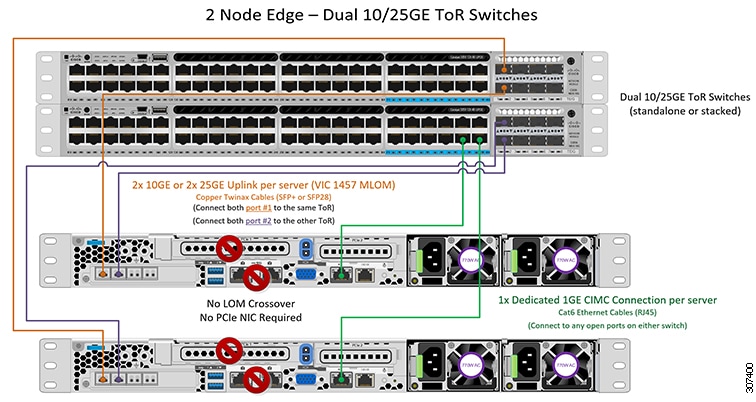
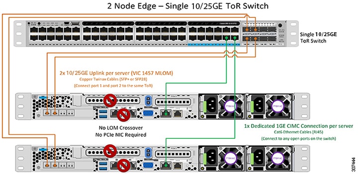
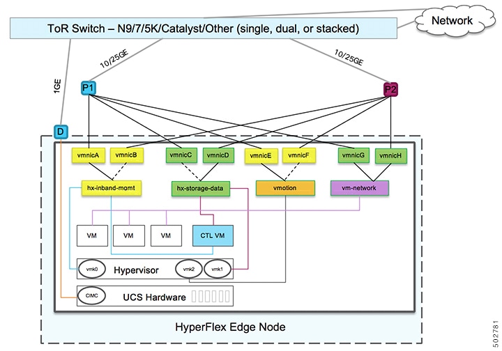
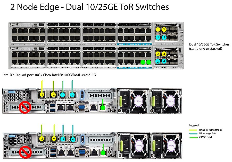
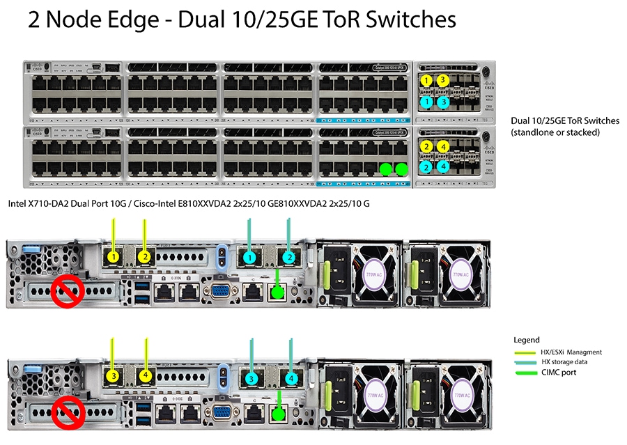
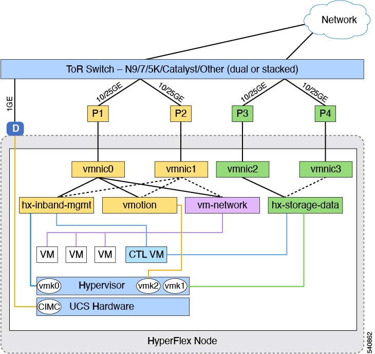
  • 10/25Gigabit (GE) topology with Cisco VIC-based hardware or Intel NIC-Based adapters.

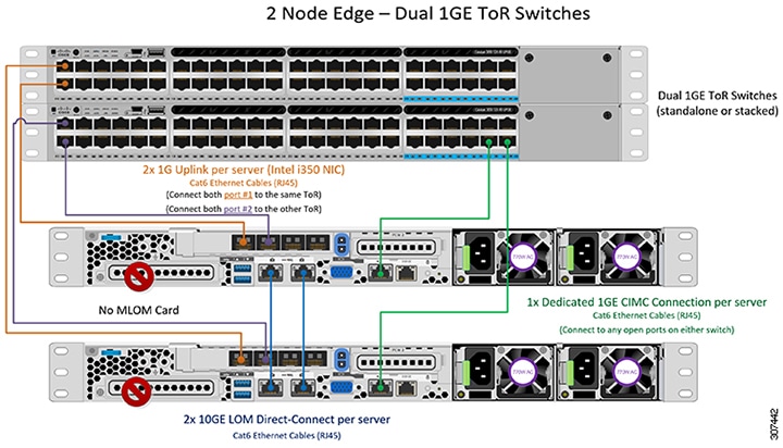
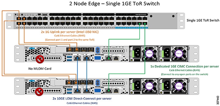
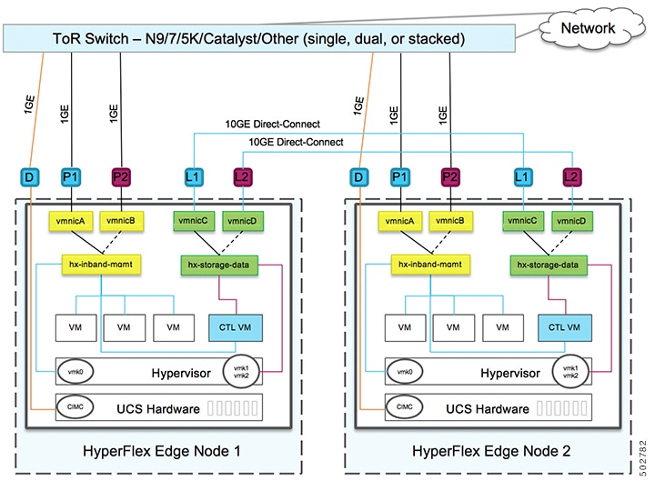
  • 1GE topology, for clusters that will not need node expansion and where the top-of-rack ToR switch does not have 10GE ports available.

For more specific information on Cisco IMC Connectivity, physical cabling, network design, and configuration guidelines, select from the following list of available topologies:

After completing the 10/25GE or 1GE ToR physical network and cabling section, continue with the Common Network Requirement Checklist.

10 or 25GE VIC-Based Topology

10 or 25GE VIC-Based Topology

The 10 or 25 Gigabit Ethernet (GE) switch topology provides a fully redundant design that protects against switch (if using dual or stacked switches), link and port failures. The 10/25GE switch may be one or two standalone switches or may be formed as a switch stack.

Cisco IMC Connectivity for 10/25GE VIC-Based Topology

Choose one of the following Cisco IMC Connectivity options for the 2-node 10/25 Gigabit Ethernet (GE) topology:

  • Use of a dedicated 1GE Cisco IMC management port is recommended. This option requires additional switch ports and cables, however it avoids network contention and ensures always on, out of band access to each physical server.

  • Use of shared LOM extended mode (EXT). In this mode, single wire management is used and Cisco IMC traffic is multiplexed onto the 10/25GE VIC connections. When operating in this mode, multiple streams of traffic are shared on the same physical link and uninterrupted reachability is not guaranteed. This deployment option is not recommended.

    • In fabric interconnect-based environments, built in QoS ensures uninterrupted access to Cisco IMC and server management when using single wire management. In HyperFlex Edge environments, QoS is not enforced and hence the use of a dedicated management port is recommended.

  • Assign an IPv4 management address to the Cisco IMC following the procedures in the Server Installation and Service Guide for the equivalent Cisco UCS C-series server. HyperFlex does not support IPv6 addresses.

Physical Network and Cabling for 10/25GE VIC-Based Topology

A managed switch (1 or 2) with VLAN capability is required. Cisco fully tests and provides reference configurations for Catalyst and Nexus switching platforms. Choosing one of these switches provides the highest level of compatibility and ensures a smooth deployment and seamless ongoing operations.

Dual switch configuration provides a slightly more complex topology with full redundancy that protects against: switch failure, link failure, and port failure. It requires two switches that may be standalone or stacked, and two 10/25GE ports, one 1GE port for CIMC management, and one Cisco VIC 1457 per server. Trunk ports are the only supported network port configuration.

Single switch configuration provides a simple topology requiring only a single switch, and two 10/25GE ports, one 1GE port for CIMC management, and one Cisco VIC 1457 per server. Switch level redundancy is not provided, however all links/ports and associated network services are fully redundant and can tolerate failures.

Requirements for both 10 and 25GE Topologies

The following requirements are common to both 10/25GE topologies and must be met before starting deployment:

  • Dedicated 1 Gigabit Ethernet (GE) Cisco IMC management port per server (recommended)

    • 2 x 1GE ToR switch ports and two (2) Category 6 ethernet cables for dedicated Cisco IMC management port (customer supplied)

  • Cisco VIC 1457 (installed in the MLOM slot in each server)

    • Prior generation Cisco VIC hardware is not supported for 2 node or 4 node HX Edge clusters.

    • 4 x 10/25GE ToR switch ports and 4 x 10/25GE SFP+ or SFP28 cables (customer supplied. Ensure the cables you select are compatible with your switch model).

    • Cisco VIC 1457 supports 10GE interface speeds.

    • Cisco VIC 1457 supports 25GE interface speeds.

    • Cisco VIC 1457 does not support 40GE internet speeds.

    • Port channels are not supported.

Requirements for HX Edge clusters using 25GE


Note


Using 25GE mode typically requires the use of forward error correction (FEC) depending on the transceiver or the type & length of cabling selected. The VIC 1400 series by default is configured in CL91 FEC mode (FEC mode “auto” if available in the Cisco IMC UI is the same as CL91) and does not support auto FEC negotiation. Certain switches will need to be manually set to match this FEC mode to bring the link state up. The FEC mode must match on both the switch and VIC port for the link to come up. If the switch in use does not support CL91, you may configure the VIC ports to use CL74 to match the FEC mode available on the switch. This will require a manual FEC mode change in the CIMC UI under the VIC configuration tab. Do not start a HyperFlex Edge deployment until the link state is up as reported by the switch and the VIC ports. CL74 is also known as FC-FEC (Firecode) and CL91 is also known as RS-FEC (Reed Solomon). See the Cisco UCS C-Series Integrated Management Controller GUI Configuration Guide, Release 4.1 for further details on how to change the FEC mode configured on the VIC using the Cisco IMC GUI.


Next Step:

Select either a single switch or dual switch configuration to continue with physical cabling:

10/25GE VIC-Based Dual Switch Physical Cabling


Warning


Proper cabling is important to ensure full network redundancy.

To deploy with dual ToR switches for extra redundancy (see diagram below for a visual layout):

  • If using dedicated Cisco IMC, connect the 1GE management port on each server (Labeled M on the back of the server) to one of the two switches.

  • Connect one out of the four 10/25GE ports on the Cisco VIC from each server to the same ToR switch.

    • Use the same port number on each server to connect to the same switch.


      Note


      Failure to use the same VIC port numbers will result in an extra hop for traffic between servers and will unnecessarily consume bandwidth between the two switches.
  • Connect a second 10/25GE port on the Cisco VIC from each server to the other ToR switch. Use the same port number on each server to connect to the same switch.

  • Do not connect additional 10/25GE ports prior to cluster installation. After cluster deployment, you may optionally use the additional two 10/25GE ports for guest VM traffic.

10/25GE VIC-Based Single Switch Physical Cabling


Warning


Proper cabling is important to ensure full network redundancy.

To deploy with a single ToR (see diagram below for a visual layout):

  • If using dedicated Cisco IMC, connect the 1GE management port on each server (Labeled M on the back of the server) to the switch.

  • Connect any two out of the four 10/25GE ports on the Cisco VIC from each server to the same ToR switch.

  • Do not connect additional 10/25GE ports prior to cluster installation. After cluster deployment, you may optionally use the additional two 10/25GE ports for guest VM traffic.

Virtual Networking Design for 2-Node 10/25GE VIC-Based Topology

This section details the virtual network setup. No action is required as all of the virtual networking is set up automatically by the HyperFlex deployment process. These extra details are included below for informational and troubleshooting purposes.

Virtual Switches:

Four vSwitches are required:

  • vswitch-hx-inband-mgmt—ESXi management (vmk0), storage controller management network

  • vswitch-hx-storage-data—ESXi storage interface (vmk1), HX storage controller data network

  • vmotion—vMotion interface (vmk2)

  • vswitch-hx-vm-network—VM guest portgroups

Network Topology

Failover Order:

  • vswitch-hx-inband-mgmt—entire vSwitch is set for active/standby. All services by default consume a single uplink port and failover when needed.

  • vswitch-hx-storage-data—HyperFlex storage data network and vmk1 are with the opposite failover order as inband-mgmt and vmotion vSwitches to ensure traffic is load balanced.

  • vmotion—The vMotion VMkernel port (vmk2) is configured when using the post_install script. Failover order is set for active/standby.

  • vswitch-hx-vm-network—vSwitch is set for active/active. Individual portgroups can be overridden as needed.

10/25GE VIC-based Switch Configuration Guidelines

3 VLANs are required at a minimum.

  • 1 VLAN for the following connections: VMware ESXi management, Storage Controller VM management and Cisco IMC management.

    • VMware ESXi management and Storage Controller VM management must be on the same subnet and VLAN.

    • A dedicated Cisco IMC management port may share the same VLAN with the management interfaces above or may optionally use a dedicated subnet and VLAN. If using a separate VLAN, it must have L3 connectivity to the management VLAN above and must meet Intersight connectivity requirements.

    • If using shared LOM extended mode for Cisco IMC management, a dedicated VLAN is recommended.

  • 1 VLAN for Cisco HyperFlex storage traffic. This can and should be an isolated and non-routed VLAN. It must be unique and cannot overlap with the management VLAN.

  • 1 VLAN for vMotion traffic. This can be an isolated and non-routed VLAN.


    Note


    It is not possible to collapse or eliminate the need for these VLANs. The installation will fail if attempted.
  • Additional VLANs as needed for guest VM traffic. These VLANs will be configured as additional portgroups in ESXi and should be trunked and allowed on all server facing ports on the ToR switch.

    • These additional guest VM VLANs are optional. You may use the same management VLAN above for guest VM traffic in environments that wish to keep a simplified flat network design.


      Note


      Due to the nature of the Cisco VIC carving up multiple vNICs from the same physical port, it is not possible for guest VM traffic configured on vswitch-hx-vm-network to communicate L2 to interfaces or services running on the same host. It is recommended to either a) use a separate VLAN and perform L3 routing or b) ensure any guest VMs that need access to management interfaces be placed on the vswitch-hx-inband-mgmt vSwitch. In general, guest VMs should not be put on any of the HyperFlex configured vSwitches except for the vm-network vSwitch. An example use case would be if you need to run vCenter on one of the nodes and it requires connectivity to manage the ESXi host it is running on. In this case, use one of the recommendations above to ensure uninterrupted connectivity.
  • Switchports connected to the Cisco VIC should be configured in trunk mode with the appropriate VLANs allowed to pass.

  • Switchports connected to the dedicated Cisco IMC management port should be configured in ‘Access Mode’ on the appropriate VLAN.

  • All cluster traffic will traverse the ToR switches in the 10/25GE topology

  • Spanning tree portfast trunk (trunk ports) should be enabled for all network ports


    Note


    Failure to configure portfast may cause intermittent disconnects during ESXi bootup and longer than necessary network re-convergence during physical link failure

Additional Considerations:

  • Additional 3rd party NIC cards may be installed in the HX Edge nodes as needed. See the section in chapter 1 with the link to the networking guide.

  • All non-VIC interfaces must be shut down or left un-cabled until installation is completed

  • Only a single VIC is supported per HX Edge node in the MLOM slot. PCIe based VIC adapters are not supported with HX Edge nodes.

Jumbo Frames for 10/25 GE VIC-Based

Jumbo frames are typically used to reduce the number of packets transmitted on your network and increase efficiency. The following describes the guidelines to using jumbo frames on your 10/25GE topology.

  • The option to enable jumbo frames is only provided during initial install and cannot be changed later.

  • Jumbo Frames are a best practice, but are not required. If opting out of jumbo frames, leave the MTU set to 1500 bytes on all network switches.

  • For highest performance, jumbo frames may be optionally enabled. Ensure full path MTU is 9000 bytes or greater. Keep the following considerations in mind when enabling jumbo frames:

    • When running a dual switch setup, it is imperative that all switch interconnects and switch uplinks have jumbo frames enabled. Failure to ensure full path MTU could result in a cluster outage if traffic is not allowed to pass after link or switch failure.

    • The HyperFlex installer will perform a one-time test on initial deployment that will force the failover order to use the standby link on one of the nodes. If the switches are cabled correctly, this will test the end to end path MTU. Do no bypass this warning if a failure is detected. Correct the issue and retry the installer to ensure the validation check passes.

    • For these reasons and to reduce complexity, it is recommended to disable jumbo frames when using a dual switch setup.

  • The option to enable jumbo frames is found in the HyperFlex Cluster profile, under the Network Configuration policy. Checking the box will enable jumbo frames. Leaving the box unchecked will keep jumbo frames disabled.

Next Steps:

Complete the Common Network Requirement Checklist.

10 or 25GE NIC-Based Topology

10 or 25GE NIC-Based Topology

The 10 or 25 Gigabit Ethernet (GE) switch NIC-based topology provides a fully redundant design that protects against switch (if using dual or stacked switches), link and port failures. The 10/25GE switch may be one or two standalone switches or may be formed as a switch stack.

The 10 or 25 Gigabit Ethernet (GE) network interface card (NIC)-based topology is an option in place of a VIC-based topology. Both NIC- and VIC-based topologies provide a fully redundant design that protects against switch (if using dual or stacked switches), link and port failures. The 10/25GE switch may be one or two standalone switches or may be formed as a switch stack. Before you consider deploying a NIC-based topology, consider the following requirements and supported hardware.

Requirements for NIC-Based Topology

The following requirements and hardware must be considered before starting deployment:

  • NIC-based deployment is supported on HXDP release 5.0(2a) and later

  • VMware ESXi 7.0 U3 or later

  • NIC-Based cluster is supported for Intersight deployment only and requires an Intersight Essentials License

  • NIC-Based HX deployments are supported with HX 220/225/240/245 M6 nodes only.

  • Support for Edge and DC-no-FI clusters only

  • 10/25GE Dual Top of Rack (ToR) Switches

  • One Intel 710/810 series quad port NIC or two Intel 710/810 series dual port NICs installed on Cisco HX hardware. Supported NIC options are:

    • Intel X710-DA2 Dual Port 10Gb SFP+ NIC (HX-PCIE-ID10GF)

    • Intel X710 Quad-port 10G SFP+ NIC (HX-PCIE-IQ10GF)

    • Cisco-Intel E810XXVDA2 2x25/10 GbE SFP28 PCIe NIC (HX-P-I8D25GF)

    • Cisco-Intel E810XXVDA4L 4x25/10 GbE SFP28 PCIe NIC (HX-P-I8Q25GF)

Cisco IMC Connectivity for 10/25GE NIC-Based Topology

Choose one of the following Cisco IMC Connectivity options for the 2-node 10/25 Gigabit Ethernet (GE) topology:

  • Use of a dedicated 1GE Cisco IMC management port is recommended. This option requires additional switch ports and cables, however it avoids network contention and ensures always on, out of band access to each physical server.

  • Use of shared LOM extended mode (EXT). In this mode, single wire management is used and Cisco IMC traffic is multiplexed onto the 10/25GE VIC connections. When operating in this mode, multiple streams of traffic are shared on the same physical link and uninterrupted reachability is not guaranteed. This deployment option is not recommended.

  • Assign an IPv4 management address to the Cisco IMC following the procedures in the Server Installation and Service Guide for the equivalent Cisco UCS C-series server. HyperFlex does not support IPv6 addresses.

Physical Network and Cabling for 10/25GE NIC-Based Topology

Two managed switches with VLAN capability are required. Cisco fully tests and provides reference configurations for Catalyst and Nexus switching platforms. Choosing one of these switches provides the highest level of compatibility and ensures a smooth deployment and seamless ongoing operations.

Dual switch configuration provides a slightly more complex topology with full redundancy that protects against: switch failure, link failure, and port failure. It requires two switches that may be standalone or stacked, and four 10/25GE ports, one 1GE port for CIMC management, and one quad port or two dual port NICs per server. Trunk ports are the only supported network port configuration and port-channels are not supported.

Requirements for both 10 and 25GE Topologies

The following requirements are common to both 10/25GE topologies and must be met before starting deployment:

  • Dedicated 1 Gigabit Ethernet (GE) Cisco IMC management port per server (recommended)

  • 2 x 1GE ToR switch ports and two (2) Category 6 ethernet cables for dedicated Cisco IMC management port (customer supplied)

  • One Intel Quad port NIC or two Intel dual port NICs installed in the PCIE slots as below:

    • HX 220/225 Nodes: Use PCIE slot 1 for quad port NIC or use PCIE slots 1 & 2 for dual port

    • NICs HX 240/245 Nodes: Use PCIE slot 4 for quad port NIC or use PCIE slot 4 & 6 for dual port NICs

Next Step:

After completing the 10/25GE or 1GE ToR physical network and cabling section, continue with the Common Network Requirement Checklist.

10/25GE NIC-Based Dual Switch Physical Cabling


Warning


Proper cabling is important to ensure full network redundancy.

To deploy with dual ToR switches for extra redundancy (see diagram below for a visual layout):

  • If using dedicated Cisco IMC, connect the 1GE management port on each server (Labeled M on the back of the server) to one of the two switches.


    Note


    Failure to use the same NIC port numbers will result in an extra hop for traffic between servers and will unnecessarily consume bandwidth between the two switches.
  • Connect the first NIC port (going from left) from each node to the first ToR switch (switchA).

  • Connect the second NIC port (going from left) from each node to the second ToR switch (switchB).

  • Connect the third NIC port (going from left) from each node to first ToR switch (switchA).

  • Connect the fourth NIC port (going from left) from each node to the second ToR switch (switchB).


Note


Follow the guidelines above for cabling. Deviating from the recommendations above may result in cluster deployment failure.


Note


Use the same port number on each server to connect to the same switch. Refer to the topology diagram below for connectivity details.


Network Cabling Diagram for 1 x Quad Port NIC

Network Cabling Diagram for 2 x Dual Port NICs

Virtual Networking Design for 2-Node 10/25 GE NIC-Based Topology

This section details the virtual network setup. No action is required as all of the virtual networking is set up automatically by the HyperFlex deployment process. These extra details are included below for informational and troubleshooting purposes.

Virtual Switches:

Four vSwitches are required:

  • vswitch-hx-inband-mgmt—ESXi management (vmk0), storage controller management network, vMotion interface (vmk2) and guest VM portgroups

  • vswitch-hx-storage-data—ESXi storage interface (vmk1), HX storage controller data network

Network Topology

Failover Order:

  • vswitch-hx-inband-mgmt—entire vSwitch is set for active/standby. All services by default consume a single uplink port and failover when needed.

  • vswitch-hx-storage-data—HyperFlex storage data network and vmk1 are with the opposite failover order as inband-mgmt and vmotion vSwitches to ensure traffic is load balanced.

10/25GE NIC-Based Switch Configuration Guidelines

3 VLANs are required at a minimum.

  • 1 VLAN for the following connections: VMware ESXi management, Storage Controller VM management and Cisco IMC management.

    • This VLAN should be configured as the trunk VLAN on all the switch ports connected to port 1 and port 2 from left on each node

    • VMware ESXi management and Storage Controller VM management must be on the same subnet and VLAN.

    • A dedicated Cisco IMC management port may share the same VLAN with the management interfaces above or may optionally use a dedicated subnet and VLAN. If using a separate VLAN, it must have L3 connectivity to the management VLAN above and must meet Intersight connectivity requirements.

    • If using shared LOM extended mode for Cisco IMC management, a dedicated VLAN is recommended.

  • 1 VLAN for Cisco HyperFlex storage traffic. This can and should be an isolated and non-routed VLAN. It must be unique and cannot overlap with the management VLAN. This VLAN should be configured as a trunk VLAN on all the switch ports connected to port 3 and port 4 from the left on each node.

  • 1 VLAN for vMotion traffic. This can be an isolated and non-routed VLAN. In a NIC-Based HX cluster, the vSwitch vswitch-hx-inband-mgmt is used for vMotion and guest VM networking. So, the VLANs used for vMotion and guest VM networking should be trunked on all switch ports connected to port 1 and port 2 from the left on each node.


    Note


    It is not possible to collapse or eliminate the need for these VLANs. The installation will fail if attempted.
  • Switchports connected to the NICs should be configured in trunk mode with the appropriate VLANs allowed to pass.

  • Switch ports connected to the NICs in a NIC-based cluster should be operating at dedicated 10/25GE speed.

  • Switchports connected to the dedicated Cisco IMC management port should be configured in ‘Access Mode’ on the appropriate VLAN.

  • All cluster traffic will traverse the ToR switches in the 10/25GE topology

  • Spanning tree portfast trunk (trunk ports) should be enabled for all network ports


    Note


    Failure to configure portfast may cause intermittent disconnects during ESXi bootup and longer than necessary network re-convergence during physical link failure

Additional Considerations:

  • Additional NIC cards may be installed in the HX Edge nodes as needed. See the section in Chapter 1 with the link to the Networking guide.

  • All other VIC or NIC cards in slots other than 1 and 2 in HX 220/225 nodes, or slots 4 and 6 in HX 240/245 nodes must be shut down or left un-cabled until installation is complete.

Jumbo Frames for 10/25GE NIC-Based

Jumbo frames are typically used to reduce the number of packets transmitted on your network and increase efficiency. The following describes the guidelines to using jumbo frames on your 10/25GE topology.

  • The option to enable jumbo frames is only provided during initial install and cannot be changed later.

  • Jumbo Frames are a best practice, but are not required. If opting out of jumbo frames, leave the MTU set to 1500 bytes on all network switches.

  • For highest performance, jumbo frames may be optionally enabled. Ensure full path MTU is 9000 bytes or greater. Keep the following considerations in mind when enabling jumbo frames:

    • When running a dual switch setup, it is imperative that all switch interconnects and switch uplinks have jumbo frames enabled. Failure to ensure full path MTU could result in a cluster outage if traffic is not allowed to pass after link or switch failure.

    • The HyperFlex installer will perform a one-time test on initial deployment that will force the failover order to use the standby link on one of the nodes. If the switches are cabled correctly, this will test the end-to-end path MTU. Do not bypass this warning if a failure is detected. Correct the issue and retry the installer to ensure the validation check passes.

    • For these reasons and to reduce complexity, it is recommended to disable jumbo frames when using a dual switch setup.

  • The option to enable jumbo frames is found in the HyperFlex Cluster profile, under the Network Configuration policy. Checking the box will enable jumbo frames. Leaving the box unchecked will keep jumbo frames disabled.

Next Steps:

Complete the Common Network Requirement Checklist.

1 Gigabit Ethernet Topology

1 Gigabit Ethernet Topology

The 1 Gigabit Ethernet (GE) switch topology provides a fully redundant design that protects against switch (if using dual or stacked switches), link and port failures. The 1GE switch may be one or two standalone switches or may be formed as a switch stack.


Note


Single or dual 1GB switch connectivity limits the maximum performance that virtual machines can get and is not recommended for applications requiring high performance.


Cisco IMC Connectivity for 1 Gigabit Ethernet Topology

Cisco IMC Connectivity for your 2-node 1 Gigabit Ethernet (GE) topology requires the use of the dedicated 1GE Cisco IMC management port. Other operating modes, including shared LOM mode, are not available due to the use of direct connect cables in this topology.

Assign an IPv4 management address to the Cisco IMC following the procedures in the Server Installation and Service Guide for the equivalent Cisco UCS C-series server. HyperFlex does not support IPv6 addresses.

Physical Network and Cabling for 1 GE Topology

A managed switch (1 or 2) with VLAN capability is required. Cisco fully tests and provides reference configurations for Catalyst and Nexus switching platforms. Choosing one of these switches provides the highest level of compatibility and ensures a smooth deployment and seamless ongoing operations.

Dual switch cabling provides a slightly more complex topology with full redundancy that protects against: switch failure, link failure, and switch port failure. It requires two switches that may be standalone or stacked, and three 1 Gigabit Ethernet (GE) switch ports per server. Single switch cabling provides a simple topology requiring only single switch and three 1GE switch ports per server. Switch level redundancy is not provided, however all links/ports and associated network services are fully redundant and can tolerate failures.

The 1GE topology uses direct-connect cables for high speed, redundant, 10GE connectivity between the two nodes without the need for a 10GE capable switch.


Note


This topology does not support future node expansion capability and should be avoided where requirements may dictate adding more HX Edge nodes in the future.

The following requirements are common to both 1GE topologies and must be met before starting deployment:

  • Dedicated 1 Gigabit Ethernet (GE) Cisco IMC management port per server (required)

  • Intel i350 Quad Port PCIe NIC Card (installed in a PCIe slot in each server) (required)

    • Cisco VIC is not used in this topology

  • 2 x 10GE DirectConnect LAN-on-Motherboard (LOM) connections (do not consume switchports)

    • 2 x Category 6 straight through ethernet cables for direct connect links (customer supplied)

  • 6 x 1GE Top of Rack (ToR) switchports and 6x Category 6 ethernet cables (customer supplied)

  • Port channels are not supported.

Select either a single switch or dual switch configuration to continue with physical cabling:

1 Gigabit Ethernet Dual Switch Cabling


Warning


Proper cabling is important to ensure full network redundancy.

To deploy with dual ToR switches for extra redundancy (see diagram below for a visual layout):

  • Connect the 1GE dedicated Cisco IMC management port on each server (Labeled M on the back of the server) to one of the two switches.

  • Connect the Lan-on-motherboard (LOM) port 1 on one server to the LOM port 1 on the other server using a regular ethernet cable.

  • Connect LOM port 2 on one server to LOM port 2 on the second server.

  • Connect one out of the four 1GE ports on the i350 NIC from each server to the same ToR switch. Use the same port number on each server to connect to the same switch.


    Note


    Failure to use the same port numbers will result in an extra hop for traffic between servers and will unnecessarily consume bandwidth between the two switches.


  • Connect a second 1GE port on the i350 NIC from each server to the other ToR switch. Use the same port number on each server to connect to the same switch.

  • Do not connect additional 1GE ports prior to cluster installation. After cluster deployment, you may optionally use the additional two 1GE ports for guest VM traffic.

1 Gigabit Ethernet Single Switch Cabling


Warning


Proper cabling is important to ensure full network redundancy.

To deploy with a single ToR (see diagram below for a visual layout):

  • Connect the 1GE dedicated Cisco IMC management port on each server (Labeled M on the back of the server) to the switch.

  • Connect the Lan-on-motherboard (LOM) port 1 on one server to the LOM port 1 on the other server using a regular ethernet cable.

  • Connect LOM port 2 on one server to LOM port 2 on the second server.

  • Connect any two out of the four 1GE ports on the i350 NIC from each server to the same ToR switch.

  • Do not connect additional 1GE ports prior to cluster installation. After cluster deployment, you may optionally use the additional two 1GE ports for guest VM traffic.

Virtual Networking Design for 2-Node 1 Gigabit Ethernet Topology

Virtual Switches:

This section details the virtual network setup. No action is required as all of the virtual networking is set up automatically by the HyperFlex deployment process. These extra details are included below for informational and troubleshooting purposes.

The recommended configuration for each ESXi calls for the following networks to be separated:

  • Management traffic network

  • Data traffic network

  • vMotion network

  • VM network

The minimum network configuration requires at least two separate networks:

  • Management network (VM network).

  • Data network (vMotion for storage traffic)

Two vSwitches each carrying different networks are required:

  • vswitch-hx-inband-mgmt—ESXi management (vmk0), HyperFlex storage controller management network, VM guest portgroups.

  • vswitch-hx-storage-data—ESXi storage interface (vmk1), vMotion interface (vmk2), HyperFlex storage controller data network.

Network Topology

Failover Order:

vswitch-hx-inband-mgmt— entire vSwitch is set for active/standby across the two uplinks. All services by default consume a single uplink port and failover when needed. Failover order for guest VM port groups may be overridden as needed and to achieve better load balancing.

vswitch-hx-storage-data— HyperFlex storage data network and vmk1 are set to the same active/standby order. The vMotion Vmkernel port is set to use the opposite order when configured using the post_install script. This ensures full utilization of the direct connect links.

1 Gigabit Ethernet Switch Configuration Guidelines

  • 1 VLAN minimum for the following connections: VMware ESXi management, Storage Controller VM Management and Cisco IMC Management.

    • VMware ESXi management and Storage Controller VM management must be on the same subnet & VLAN

    • The dedicated Cisco IMC management port may share the same VLAN with the management interfaces above or may optionally use a dedicated subnet & VLAN. If using a separate VLAN, it must have L3 connectivity to the management VLAN above and must meet Intersight connectivity requirements.

  • Additional VLANs as needed for guest VM traffic. These VLANs will be configured as additional portgroups in ESXi and should be trunked on all connections to the ToR switch.

    • These additional guest VM VLANs are optional. You may use the same management VLAN above for guest VM traffic in environments that wish to keep a simplified flat network design.

  • Switchports connected to the Intel i350 should be configured in trunk mode with the appropriate VLANs allowed to pass.

  • Switchports connected to the dedicated Cisco IMC management port should be configured in ‘Access Mode’ on the appropriate VLAN.

  • VMware vMotion traffic and Cisco HyperFlex data traffic will traverse the direct connect LOMs and will therefore not utilize the top of rack switch. Hence additional VLANs are not required for these services.

    • Configuration of Jumbo Frames on the ToR switch is not required in this topology due to all traffic remaining local without need to traverse upstream switches. This topology therefore defaults vMotion traffic to use jumbo frames for high performance.

  • Spanning tree portfast trunk (trunk ports) should be enabled for all network ports


    Note


    Failure to configure portfast may cause intermittent disconnects during ESXi bootup and longer than necessary network re-convergence during physical link failure

Jumbo Frames for 1 Gigabit Ethernet

Jumbo frames are typically used to reduce the number of packets transferred on your network. The following describes the guidelines to using jumbo frames on your 1GE topology.

  • Jumbo Frames are automatically configured on the vMotion network as there is no additional setup required.

  • Jumbo Frames are a best practice, but are not required. If opting out of jumbo frames, leave the MTU set to 1500 bytes on all network switches.

  • The option to enable jumbo frames is found in the HyperFlex Cluster profile, under the Network Configuration policy. When using the 1GE topology, you may choose to enable jumbo frames by ensuring the check box is enabled before starting deployment.

Next Steps:

Complete the Common Network Requirement Checklist.

10GBASE-T Copper Support

HX Edge supports the use of Cisco copper 10G transceivers (SFP-10G-T-X) for use with switches that have 10G copper (RJ45) ports. In all of the 10GE topologies listed in this chapter, supported twinax, fiber, or 10G copper transceivers may be used. For more information on supported optics and cables, see the Cisco UCS Virtual Interface Card 1400/14000 Series Data Sheet.

Limitations

When using SFP-10G-T-X transceivers with HyperFlex Edge, the following limitations apply:

  • Minimum Cisco IMC firmware verison 4.1(3d) and HyperFlex Data Platform version 4.5(2a).

  • Maximum of two SFP-10G-T-X may be used per VIC. Do not use the additional two ports.

  • The server must not use Cisco Card or Shared LOM Extended NIC modes. Use the Dedicated or Shared LOM NIC modes only.

Common Network Requirement Checklist

Before you begin installation, confirm that your environment meets the following specific software and hardware requirements.

VLAN Requirements


Important


Reserved VLAN IDs - The VLAN IDs you specify must be supported in the Top of Rack (ToR) switch where the HyperFlex nodes are connected. For example, VLAN IDs 3968 to 4095 are reserved by Nexus switches and VLAN IDs 1002 to 1005 are reserved by Catalyst switches. Before you decide the VLAN IDs for HyperFlex use, make sure that the same VLAN IDs are available on your switch.


Network

VLAN ID

Description

Use a separate subnet and VLANs for each of the following networks:

VLAN for VMware ESXi, and Cisco HyperFlex management

Used for management traffic among ESXi, HyperFlex, and VMware vCenter, and must be routable.

Note

 
This VLAN must have access to Intersight (Intersight is required for 2-Node deployment).

CIMC VLAN

Can be same or different from the Management VLAN.

Note

 
This VLAN must have access to Intersight (Intersight is required for 2-Node deployment).

VLAN for HX storage traffic

Used for raw storage traffic and requires only L2 connectivity.

VLAN for VMware vMotion

Used for vMotion VLAN.

VLAN(s) for VM network(s)

Used for VM/application network.

Note

 
Can be multiple VLANs, each backed by a different VM portgroup in ESXi.

Supported vCenter Topologies

Use the following table to determine the topology supported for vCenter.

Topology

Description

Recommendation

Single vCenter

Virtual or physical vCenter that runs on an external server and is local to the site. A management rack mount server can be used for this purpose.

Highly recommended

Centralized vCenter

vCenter that manages multiple sites across a WAN.

Highly recommended

Nested vCenter

vCenter that runs within the cluster you plan to deploy.

Installation for a HyperFlex Edge cluster may be initially performed without a vCenter. Alternatively, you may deploy with an external vCenter and migrate it into the cluster. In either case, the cluster must be registered to a vCenter server before running production workloads.

For the latest information, see the How to Deploy vCenter on the HX Data Platform tech note.

Customer Deployment Information

A typical two-node HyperFlex Edge deployment requires 9 IP addresses – 7 IP addresses for the management network and 2 IP addresses for the vMotion network.


Important


All IP addresses must be IPv4. HyperFlex does not support IPv6 addresses.


CIMC Management IP Addresses

Server

CIMC Management IP Addresses

Server 1:

Server 2:

Subnet mask

Gateway

DNS Server

NTP Server

Note

 
NTP configuration on CIMC is required for proper Intersight connectivity.

Network IP Addresses


Note


By default, the HX Installer automatically assigns IP addresses in the 169.254.X.X range as a /24 network, to the Hypervisor Data Network and the Storage Controller Data Network. This IP subnet is not user configurable.


Note


Spanning Tree portfast trunk (trunk ports) should be enabled for all network ports.

Failure to configure portfast may cause intermittent disconnects during ESXi bootup and longer than necessary network re-convergence during physical link failure.


Management Network IP Addresses

(must be routable)

Hypervisor Management Network

Storage Controller Management Network

Server 1:

Server 1:

Server 2:

Server 2:

Storage Cluster Management IP address

Cluster IP:

Subnet mask

Default gateway

VMware vMotion Network IP Addresses

For vMotion services, you may configure a unique VMkernel port or, if necessary, reuse the vmk0 if you are using the management VLAN for vMotion (not recommended).

Server

vMotion Network IP Addresses (configured using the post_install script)

Server 1:

Server 2:

Subnet mask

Gateway

VMware vCenter Configuration


Note


HyperFlex communicates with vCenter through standard ports. Port 80 is used for reverse HTTP proxy and may be changed with TAC assistance. Port 443 is used for secure communication to the vCenter SDK and may not be changed.

vCenter admin username

username@domain

vCenter admin password

vCenter data center name

Note


An existing datacenter object can be used. If the datacenter doesn't exist in vCenter, it will be created.

VMware vSphere compute cluster and storage cluster name

Note


Cluster name you will see in vCenter.

Port Requirements


Important


Ensure that the following port requirements are met in addition to the prerequisites listed for Intersight Connectivity.

If your network is behind a firewall, in addition to the standard port requirements, VMware recommends ports for VMware ESXi and VMware vCenter.

  • CIP-M is for the cluster management IP.

  • SCVM is the management IP for the controller VM.

  • ESXi is the management IP for the hypervisor.

The comprehensive list of ports required for component communication for the HyperFlex solution is located in Appendix A of the HX Data Platform Security Hardening Guide


Tip


If you do not have standard configurations and need different port settings, refer to Table C-5 Port Literal Values for customizing your environment.


Network Services


Note


  • DNS and NTP servers should reside outside of the HX storage cluster.

  • Use an internally-hosted NTP server to provide a reliable source for the time.

  • All DNS servers should be pre-configured with forward (A) and reverse (PTR) DNS records for each ESXi host before starting deployment. When DNS is configured correctly in advance, the ESXi hosts are added to vCenter via FQDN rather than IP address.

    Skipping this step will result in the hosts being added to the vCenter inventory via IP address and require users to change to FQDN using the following procedure: Changing Node Identification Form in vCenter Cluster from IP to FQDN.


DNS Servers

<Primary DNS Server IP address, Secondary DNS Server IP address, …>

NTP servers

<Primary NTP Server IP address, Secondary NTP Server IP address, …>

Time zone

Example: US/Eastern, US/Pacific

Connected Services

Enable Connected Services (Recommended)

Yes or No required

Email for service request notifications

Example: name@company.com

Proxy Server

  • Use of a proxy server is optional if direct connectivity to Intersight is not available.

  • When using a proxy, the device connectors in each server must be configured to use the proxy in order to claim the servers into an Intersight account. In addition, the proxy information must be provided in the HX Cluster Profile to ensure the HyperFlex Data Platform can be successfully downloaded.

  • Use of username/password is optional

Proxy required: Yes or No

Proxy Host

Proxy Port

Username

Password

Guest VM Traffic

Considerations for guest VM traffic are given above based on the topology selection. In general, guest port groups may be created as needed so long as they are applied to the correct vSwitch:

  • 10/25GE Topology: use vswitch-hx-vm-network to create new VM port groups.

Cisco recommends you run the post_install script to add more VLANs automatically to the correct vSwitches on all hosts in the cluster. Execute hx_post_install --vlan (space and two dashes) to add new guest VLANs to the cluster at any point in the future.

Additional vSwitches may be created that use leftover vmnics or third party network adapters. Care should be taken to ensure no changes are made to the vSwitches defined by HyperFlex.


Note


Additional user created vSwitches are the sole responsibility of the administrator, and are not managed by HyperFlex.

Intersight Connectivity

Consider the following prerequisites pertaining to Intersight connectivity:

  • Before installing the HX cluster on a set of HX servers, make sure that the device connector on the corresponding Cisco IMC instance is properly configured to connect to Cisco Intersight and claimed.

  • Communication between CIMC and vCenter via ports 80, 443 and 8089 during installation phase.

  • All device connectors must properly resolve svc.intersight.com and allow outbound initiated HTTPS connections on port 443. The current version of the HX Installer supports the use of an HTTP proxy.

  • All controller VM management interfaces must properly resolve svc.intersight.com and allow outbound initiated HTTPS connections on port 443. The current version of HX Installer supports the use of an HTTP proxy if direct Internet connectivity is unavailable.

  • IP connectivity (L2 or L3) is required from the CIMC management IP on each server to all of the following: ESXi management interfaces, HyperFlex controller VM management interfaces, and vCenter server. Any firewalls in this path should be configured to allow the necessary ports as outlined in the Hyperflex Hardening Guide.

  • When redeploying HyperFlex on the same servers, new controller VMs must be downloaded from Intersight into all ESXi hosts. This requires each ESXi host to be able to resolve svc.intersight.com and allow outbound initiated HTTPS connections on port 443. Use of a proxy server for controller VM downloads is supported and can be configured in the HyperFlex Cluster Profile if desired.

  • Post-cluster deployment, the new HX cluster is automatically claimed in Intersight for ongoing management.

Cisco HyperFlex Edge Invisible Cloud Witness

The Cisco HyperFlex Edge Invisible Cloud Witness is an innovative technology for Cisco HyperFlex Edge Deployments that eliminates the need for witness VMs or arbitration software.

The Cisco HyperFlex Edge invisible cloud witness is only required for 2-node HX Edge deployments. The witness does not require any additional infrastructure, setup, configuration, backup, patching, or management of any kind. This feature is automatically configured as part of a 2-node HyperFlex Edge installation. Outbound access at the remote site must be present for connectivity to Intersight (either Intersight.com or to the Intersight Virtual Appliance). HyperFlex Edge 2-node clusters cannot operate without this connectivity in place.

For additional information about the benefits, operations, and failure scenarios of the Invisible Cloud Witness feature, see .https://www.cisco.com/c/dam/en/us/products/collateral/hyperconverged-infrastructure/hyperflex-hx-series/whitepaper-c11-741999.pdf

Ordering Cisco HyperFlex Edge Servers

When ordering Cisco HyperFlex Edge servers, be sure to choose the correct components as outlined in the HyperFlex Edge spec sheets. Pay attention to the network topology selection to ensure it matches your desired configuration. Further details on network topology PID selection can be found in the supplemental material section of the spec sheet.