Preinstallation Checklist for 2-Node 2-Room Deployments

2-Node 2-Room Network Topology

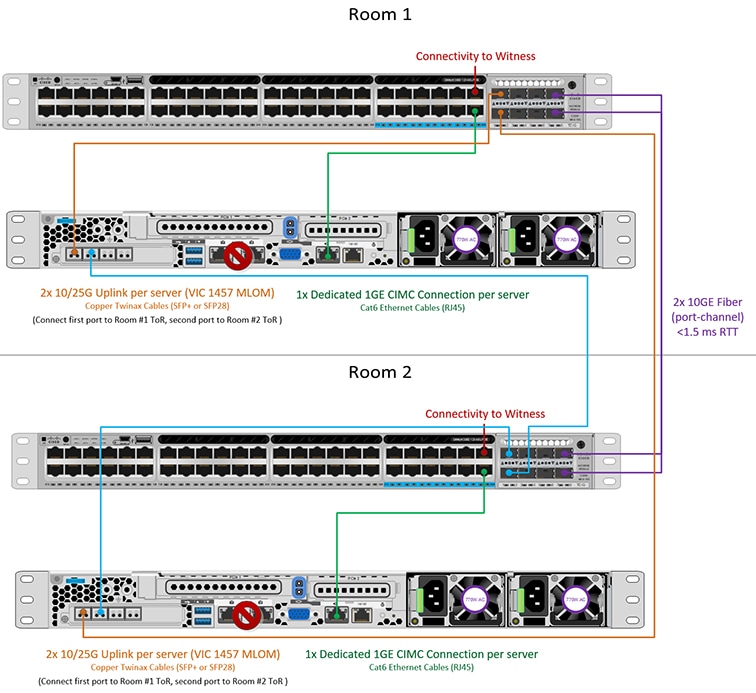
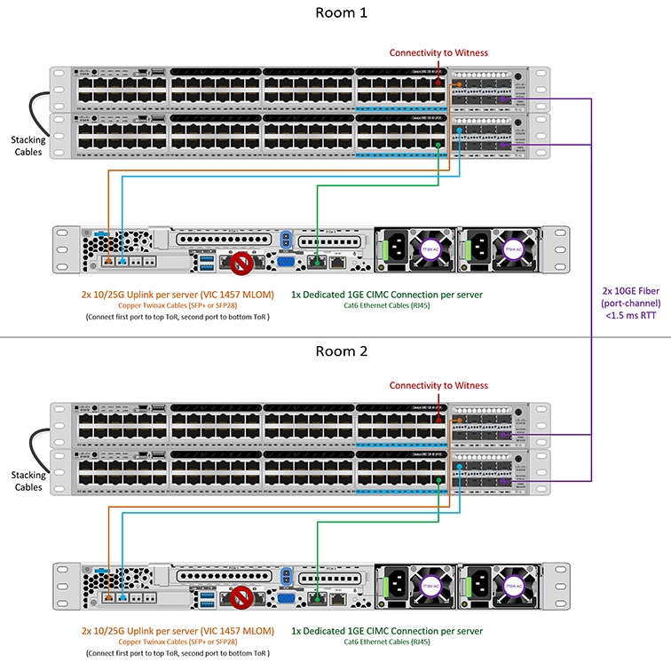
2-Node 2-Room Use Case

HyperFlex Edge offers many flexible deployment options depending on workload requirements. Standard topologies are covered in Select your 2-Node Network Topology and Selecting your 3- or 4-Node Network Topology that include single switch, dual switch, 1GE, 10GE, and 25GE options. Some designs call for placing a two-node cluster “stretched” across two rooms within a building or a campus. This type of network topology will further be referred two as a 2-node 2-room design to distinguish this type of topology from a full HyperFlex Stretched Cluster deployment.

This design is sometimes chosen as an attempt to boost the cluster availability and its ability to tolerate certain failure scenarios. Cisco does not currently recommend deploying this type of topology and recommends a properly designed 2-node cluster within the same rack. The following are some reasons why this topology is not considered a Cisco recommended best practice:

  • The ability to mitigate power failures can be handled with reliable power and use of an interruptible power supply (UPS)

  • Introduces more single points of failure – extra switching infrastructure with inter-switch links that can become oversubscribed and require proper QoS implementation

  • Complicates upgrade procedures, requiring careful planning to upgrade all components end to end.

  • Does not provide the same level of availability for mission critical applications as a HyperFlex Stretched Cluster (for more information, see the Cisco HyperFlex Systems Stretched Cluster Guide, Release 4.5. HyperFlex Edge is designed to run Edge workloads and does not provide the same performance, data resiliency, and availability guarantees. Deploy a proper stretched cluster when running mission critical applications.

  • Requirements for 10GE end to end, maximum 1.5ms RTT, and independent network paths to Intersight or local witness, described in further detail below

  • Increases overall complexity to an otherwise simple design

It is possible that a 2-node 2-room topology could unintentionally reduce availability by adding unnecessary complexity to the environment that could be otherwise mitigated through simpler means (e.g., dual redundant switches, redundant power/UPS, etc.).

Despite these best practice recommendations, it is possible and fully supported to deploy HyperFlex Edge using this topology choice. The remainder of this chapter will cover the various requirements and details to deploy such a topology.


Note


2-node 2-room topologies will never be permitted to expand beyond two converged nodes. Expansion to larger clusters is possible for other 10GE+ topologies as outlined in earlier chapters. Do not deploy this topology if cluster expansion may be required in the future.


2-Node 2-Room Requirements

The following requirements must be met when planning a 2-node 2-room deployment.

  • Networking speeds must be a minimum of 10/25GE end-to-end. This means all servers must connect to top of rack (ToR) switches using native 10/25GE and all switches must be interconnected by at least one 10GE interface, preferably more.

  • Round-Trip-Time (RTT) = the time it takes traffic to go both ways, must not exceed 1.5ms between each server room. Exceeding this threshold will result in substantial reduction in storage cluster performance. Unlike a HyperFlex Stretched Cluster with site affinity for optimized local reads, all reads and writes in a 2-node 2-room design will traverse the inter switch link (ISL) and performance is directly proportional to the network latency. For these reasons, this topology must never be used beyond campus distances (e.g., <1 km).

  • Quality of service (QoS) should be implemented at a minimum for the storage data network to prevent other background traffic from saturating the ISL and impacting storage performance. The appendix includes a sample QoS configuration for Catalyst 9300 switches.

  • Both rooms must have independent network paths to Intersight (SaaS or Appliance), which serves as the cluster witness. Without independent paths, there is no ability to tolerate the loss of either room. For example, if the Internet connection for room #1 and room #2 is serviced out of room #1, it would be impossible for room #1 to fail and for the Internet in room #2 to remain operational. This strict requirement may disqualify some environments from using a 2-node 2-room design.

  • A local witness can also be used with the design. In this case, the same principle applies; both rooms must have independent paths with no dependency on each other to be able to reach the local witness server.

  • The HyperFlex Edge 2-node, 2-room topology was introduced and is supported in HyperFlex Data Platform (HXDP) Release 4.5(1a) and later.

Selecting your 2-Node 2-Room Network Topology

To get started, select from one of the available network topologies below. Topologies are listed in priority order based on Cisco’s recommendations.

After completing the physical network and cabling section, continue with the Common Network Requirement Checklist.

10 or 25 Gigabit Ethernet Cross Connect Topology

10 or 25 Gigabit Ethernet Cross Connect Topology

The cross connect 10 or 25 Gigabit Ethernet (GE) switch topology provides a fully redundant design that protects against room, switch, link and port failures. A single 10/25GE switch is required in each room.

In this topology, each server is cross connected directly to both rooms. This provides dedicated links and prevents oversubscription to the Inter-Switch Link (ISL). This topology still requires a minimum 10GE ISL between each room to handle high bandwidth during server link failure cases.

Physical Network and Cabling for 10/25GE Cross Connect Topology

Each room requires a managed 10GE switch with VLAN capability. Cisco fully tests and provides reference configurations for Catalyst and Nexus switching platforms. Choosing one of these switches provides the highest level of compatibility and ensures a smooth deployment and seamless ongoing operations.

Each room requires: a single switch, and two 10/25GE ports, one 1GE port for CIMC management, and one Cisco VIC 1457 per server. Redundancy is provided at the room level and can tolerate the loss of either room as well as any smaller failure (e.g., switch failure, link failure, port failure).

Requirements for 10/25GE Cross Connect Topology

The following requirements must be met across both rooms before starting deployment:

  • Dedicated 1 Gigabit Ethernet (GE) Cisco IMC management port per server (recommended)

  • 2 x 1GE ToR switch ports and two (2) Category 6 ethernet cables for dedicated Cisco IMC management port (customer supplied)

  • Cisco VIC 1457 (installed in the MLOM slot in each server)

  • Prior generation Cisco VIC hardware is not supported for 2 node HX Edge clusters.

  • 4 x 10/25GE ToR switch ports and 4 x 10/25GE SFP+ or SFP28 cables (customer supplied. Ensure the cables you select are compatible with your switch model).

  • Cisco VIC 1457 supports 10GE or 25GE interface speeds.

  • Cisco VIC 1457 does not support 40GE interface speeds.

  • Port channels are not supported.

Requirements for HX Edge Clusters using 25GE

Note


Using 25GE mode typically requires the use of forward error correction (FEC) depending on the transceiver or the type & length of cabling selected. The VIC 1400 series by default is configured in CL91 FEC mode (FEC mode “auto” if available in the Cisco IMC UI is the same as CL91) and does not support auto FEC negotiation. Certain switches will need to be manually set to match this FEC mode to bring the link state up. The FEC mode must match on both the switch and VIC port for the link to come up. If the switch in use does not support CL91, you may configure the VIC ports to use CL74 to match the FEC mode available on the switch. This will require a manual FEC mode change in the CIMC UI under the VIC configuration tab. Do not start a HyperFlex Edge deployment until the link state is up as reported by the switch and the VIC ports. CL74 is also known as FC-FEC (Firecode) and CL91 is also known as RS-FEC (Reed Solomon). For more information on how to change the FEC mode configured on the VIC using the Cisco IMC GUI, see the Cisco UCS C-Series Integrated Management Controller GUI Configuration Guide, Release 4.1.


10/25 Gigabit Ethernet Cross Connect Physical Cabling


Warning


Proper cabling is important to ensure full network redundancy.
  • If using dedicated Cisco IMC, connect the 1GE management port on each server (Labeled M on the back of the server) to the local switch.

  • Connect one out of the four 10/25GE ports on the Cisco VIC from each server to the same ToR switch in room 1.

    • Use the same port number on each server to connect to the same switch.


      Note


      Failure to use the same VIC port numbers will result in an extra hop for traffic between servers and will unnecessarily consume bandwidth between the two switches.
  • Connect a second 10/25GE port on the Cisco VIC from each server to the ToR switch in room 2.

  • Do not connect additional 10/25GE ports prior to cluster installation. After cluster deployment, you may optionally use the additional two 10/25GE ports for guest VM traffic.

  • Ensure each switch has an independent network path to Intersight or a local witness server.

2-Node 2-Room Cross Connect

10 or 25 Gigabit Ethernet Stacked Switches Per Room Topology

10 or 25 Gigabit Ethernet Stacked Switches Per Room Topology

This 10 or 25 Gigabit Ethernet (GE) switch topology provides a fully redundant design that protects against room, switch, link and port failures. A switch stack of at least two 10/25GE switches is required in each room. If a switch stack is not available, dual standalone switches can be combined to achieve similar results. Ensure there is ample bandwidth between the two switches in each room and between both switch stacks across rooms.

In this topology, each server is directly connected to just the local switches in each room. Unlike the cross connect topology, the inter-switch link (ISL) is a vital component used to carry all cluster storage and management traffic between each room. The ISL must run at a minimum of 10GE with a maximum RTT latency of 1.5ms and should consist of multiple links in a port channel to ensure the links do not become saturated. With this topology, implementing qualify of service (QoS) for storage data traffic is imperative as storage traffic is mixed alongside all other background traffic between the two rooms. To ensure HyperFlex storage remains reliable and performance, implement some form of priority queueing for the storage traffic.

10/25 Gigabit Ethernet Stacked Switches Physical Cabling

Each room requires a pair of managed 10GE switches with VLAN capability. Cisco fully tests and provides reference configurations for Catalyst and Nexus switching platforms. Choosing one of these switches provides the highest level of compatibility and ensures a smooth deployment and seamless ongoing operations.

Each room requires the following: dual or stacked switches, and two 10/25GE ports, one 1GE port for CIMC management, and one Cisco VIC 1457 per server. Redundancy is provided at the room level and can tolerate the loss of either room as well as any smaller failure (e.g., switch failure, link failure, port failure).

Requirements for 10/25GE Stacked Switches Topology

The following requirements must be met across both rooms before starting deployment:

  • Dedicated 1 Gigabit Ethernet (GE) Cisco IMC management port per server (recommended)

  • 2 x 1GE ToR switch ports and two (2) Category 6 ethernet cables for dedicated Cisco IMC management port (customer supplied)

  • Cisco VIC 1457 (installed in the MLOM slot in each server)

  • Prior generation Cisco VIC hardware is not supported for 2 node HX Edge clusters.

  • 4 x 10/25GE ToR switch ports and 4 x 10/25GE SFP+ or SFP28 cables (customer supplied. Ensure the cables you select are compatible with your switch model).

  • Cisco VIC 1457 supports 10GE or 25GE interface speeds.

  • Cisco VIC 1457 does not support 40GE interface speeds.

Requirements for HX Edge Clusters using 25GE

Note


Using 25GE mode typically requires the use of forward error correction (FEC) depending on the transceiver or the type & length of cabling selected. The VIC 1400 series by default is configured in CL91 FEC mode (FEC mode “auto” if available in the Cisco IMC UI is the same as CL91) and does not support auto FEC negotiation. Certain switches will need to be manually set to match this FEC mode to bring the link state up. The FEC mode must match on both the switch and VIC port for the link to come up. If the switch in use does not support CL91, you may configure the VIC ports to use CL74 to match the FEC mode available on the switch. This will require a manual FEC mode change in the CIMC UI under the VIC configuration tab. Do not start a HyperFlex Edge deployment until the link state is up as reported by the switch and the VIC ports. CL74 is also known as FC-FEC (Firecode) and CL91 is also known as RS-FEC (Reed Solomon). For more information on how to change the FEC mode configured on the VIC using the Cisco IMC GUI, see the Cisco UCS C-Series Integrated Management Controller GUI Configuration Guide, Release 4.1.


Physical Network and Cabling for 10/25GE Stacked Switches Per Room Topology


Warning


Proper cabling is important to ensure full network redundancy.

To deploy with dual or stacked switches per room (see diagram below for a visual layout):

  • If using dedicated Cisco IMC, connect the 1GE management port on each server (Labeled M on the back of the server) to one of the two switches.

  • Connect one out of the four 10/25GE ports on the Cisco VIC from each server to the first ToR switch in the same room.

    • Use the same port number on each server to connect to the same switch.


      Note


      Failure to use the same VIC port numbers will result in an extra hop for traffic between servers and will unnecessarily consume bandwidth between the two switches.
  • Connect a second 10/25GE port on the Cisco VIC from each server to the second ToR switch in the same room. Use the same port number on each server to connect to the same switch.

  • Do not connect additional 10/25GE ports prior to cluster installation. After cluster deployment, you may optionally use the additional two 10/25GE ports for guest VM traffic.

  • Ensure each switch has an independent network path to Intersight or a local witness server.

  • Port channels are not supported.

2-Node 2-Room Dual/Stacked Switches

10 or 25 Gigabit Ethernet Single Switch Per Room Topology

10 or 25 Gigabit Ethernet Single Switch Per Room Topology

This 10 or 25 Gigabit Ethernet (GE) switch topology provides a fully redundant design that protects against room, switch, link and port failures. A single 10/25GE switch is required in each room. Ensure there is ample bandwidth between the two switches in each room.

In this topology, each server is directly connected to just the local switch in each room. Unlike the cross connect topology, the inter-switch link (ISL) is a vital component used to carry all cluster storage and management traffic between each room. The ISL must run at a minimum of 10GE with a maximum RTT latency of 1.5ms and should consist of multiple links in a port channel to ensure the links do not become saturated. With this topology, implementing quality of service (QoS) for storage data traffic is imperative as storage traffic is mixed alongside all other background traffic between the two rooms. To ensure HyperFlex storage remains reliable and performance, implement some form of priority queueing for the storage traffic.

10/25 Gigabit Ethernet Single Switch Physical Cabling


Warning


Proper cabling is important to ensure full network redundancy.

To deploy with a single switch per room (see diagram below for a visual layout):

  • If using dedicated Cisco IMC, connect the 1GE management port on each server (Labeled M on the back of the server) to the local switch.

  • Connect one out of the four 10/25GE ports on the Cisco VIC from each server to the ToR switch in the same room.

  • Connect a second 10/25GE port on the Cisco VIC from each server to the ToR switch in the same room.

  • Do not connect additional 10/25GE ports prior to cluster installation. After cluster deployment, you may optionally use the additional two 10/25GE ports for guest VM traffic.

  • Ensure each switch has an independent network path to Intersight or a local witness server.

  • Port channels are not supported.

2-Node 2-Room Single Switch

Physical Network and Cabling for 10/25GE Single Switch Per Room Topology

Each room requires a managed 10GE switch with VLAN capability. Cisco fully tests and provides reference configurations for Catalyst and Nexus switching platforms. Choosing one of these switches provides the highest level of compatibility and ensures a smooth deployment and seamless ongoing operations.

Each room requires the following: a single 10/25GE switch, and two 10/25GE ports, one 1GE port for CIMC management, and one Cisco VIC 1457 per server. Redundancy is provided at the room level and can tolerate the loss of either room as well as any smaller failure (e.g., switch failure, link failure, port failure).

Requirements for 10/25GE Single Switch Topology

The following requirements must be met across both rooms before starting deployment:

  • Dedicated 1 Gigabit Ethernet (GE) Cisco IMC management port per server (recommended)

  • 2 x 1GE ToR switch ports and two (2) Category 6 ethernet cables for dedicated Cisco IMC management port (customer supplied)

  • Cisco VIC 1457 (installed in the MLOM slot in each server)

  • Prior generation Cisco VIC hardware is not supported for 2 node HX Edge clusters.

  • 4 x 10/25GE ToR switch ports and 4 x 10/25GE SFP+ or SFP28 cables (customer supplied. Ensure the cables you select are compatible with your switch model).

  • Cisco VIC 1457 supports 10GE or 25GE interface speeds.

  • Cisco VIC 1457 does not support 40GE interface speeds.

Requirements for HX Edge Clusters using 25GE

Note


Using 25GE mode typically requires the use of forward error correction (FEC) depending on the transceiver or the type & length of cabling selected. The VIC 1400 series by default is configured in CL91 FEC mode (FEC mode “auto” if available in the Cisco IMC UI is the same as CL91) and does not support auto FEC negotiation. Certain switches will need to be manually set to match this FEC mode to bring the link state up. The FEC mode must match on both the switch and VIC port for the link to come up. If the switch in use does not support CL91, you may configure the VIC ports to use CL74 to match the FEC mode available on the switch. This will require a manual FEC mode change in the CIMC UI under the VIC configuration tab. Do not start a HyperFlex Edge deployment until the link state is up as reported by the switch and the VIC ports. CL74 is also known as FC-FEC (Firecode) and CL91 is also known as RS-FEC (Reed Solomon). For more information on how to change the FEC mode configured on the VIC using the Cisco IMC GUI, see the Cisco UCS C-Series Integrated Management Controller GUI Configuration Guide, Release 4.1.


Cisco IMC Connectivity for All 2-Node 2-Room Topologies

Choose one of the following Cisco IMC Connectivity options for the 2-node 10/25 Gigabit Ethernet (GE) topology:

  • Use of a dedicated 1GE Cisco IMC management port is recommended. This option requires additional switch ports and cables, however it avoids network contention and ensures always on, out of band access to each physical server.

  • Use of shared LOM extended mode (EXT). In this mode, single wire management is used and Cisco IMC traffic is multiplexed onto the 10/25GE VIC connections. When operating in this mode, multiple streams of traffic are shared on the same physical link and uninterrupted reachability is not guaranteed. This deployment option is not recommended.

  • In fabric interconnect-based environments, built in QoS ensures uninterrupted access to Cisco IMC and server management when using single wire management. In HyperFlex Edge environments, QoS is not enforced and hence the use of a dedicated management port is recommended.

  • Assign an IPv4 management address to the Cisco IMC. For more information, see the procedures in the Server Installation and Service Guide for the equivalent Cisco UCS C-series server. HyperFlex does not support IPv6 addresses.

10/25GE VIC-based Switch Configuration Guidelines

3 VLANs are required at a minimum.

  • 1 VLAN for the following connections: VMware ESXi management, Storage Controller VM management and Cisco IMC management.

    • VMware ESXi management and Storage Controller VM management must be on the same subnet and VLAN.

    • A dedicated Cisco IMC management port may share the same VLAN with the management interfaces above or may optionally use a dedicated subnet and VLAN. If using a separate VLAN, it must have L3 connectivity to the management VLAN above and must meet Intersight connectivity requirements.

    • If using shared LOM extended mode for Cisco IMC management, a dedicated VLAN is recommended.

  • 1 VLAN for Cisco HyperFlex storage traffic. This can and should be an isolated and non-routed VLAN. It must be unique and cannot overlap with the management VLAN.

  • 1 VLAN for vMotion traffic. This can be an isolated and non-routed VLAN.


    Note


    It is not possible to collapse or eliminate the need for these VLANs. The installation will fail if attempted.
  • Additional VLANs as needed for guest VM traffic. These VLANs will be configured as additional portgroups in ESXi and should be trunked and allowed on all server facing ports on the ToR switch.

    • These additional guest VM VLANs are optional. You may use the same management VLAN above for guest VM traffic in environments that wish to keep a simplified flat network design.


      Note


      Due to the nature of the Cisco VIC carving up multiple vNICs from the same physical port, it is not possible for guest VM traffic configured on vswitch-hx-vm-network to communicate L2 to interfaces or services running on the same host. It is recommended to either a) use a separate VLAN and perform L3 routing or b) ensure any guest VMs that need access to management interfaces be placed on the vswitch-hx-inband-mgmt vSwitch. In general, guest VMs should not be put on any of the HyperFlex configured vSwitches except for the vm-network vSwitch. An example use case would be if you need to run vCenter on one of the nodes and it requires connectivity to manage the ESXi host it is running on. In this case, use one of the recommendations above to ensure uninterrupted connectivity.
  • Switchports connected to the Cisco VIC should be configured in trunk mode with the appropriate VLANs allowed to pass.

  • Switchports connected to the dedicated Cisco IMC management port should be configured in ‘Access Mode’ on the appropriate VLAN.

  • All cluster traffic will traverse the ToR switches in the 10/25GE topology

  • Spanning tree portfast trunk (trunk ports) should be enabled for all network ports


    Note


    Failure to configure portfast may cause intermittent disconnects during ESXi bootup and longer than necessary network re-convergence during physical link failure

Additional Considerations:

  • Additional 3rd party NIC cards may be installed in the HX Edge nodes as needed. See the section in chapter 1 with the link to the networking guide.

  • All non-VIC interfaces must be shut down or left un-cabled until installation is completed

  • Only a single VIC is supported per HX Edge node in the MLOM slot. PCIe based VIC adapters are not supported with HX Edge nodes.

Virtual Networking Design for 2-Node 10/25GE VIC-Based Topology

This section details the virtual network setup. No action is required as all of the virtual networking is set up automatically by the HyperFlex deployment process. These extra details are included below for informational and troubleshooting purposes.

Virtual Switches:

Four vSwitches are required:

  • vswitch-hx-inband-mgmt—ESXi management (vmk0), storage controller management network

  • vswitch-hx-storage-data—ESXi storage interface (vmk1), HX storage controller data network

  • vmotion—vMotion interface (vmk2)

  • vswitch-hx-vm-network—VM guest portgroups

Network Topology

Failover Order:

  • vswitch-hx-inband-mgmt—entire vSwitch is set for active/standby. All services by default consume a single uplink port and failover when needed.

  • vswitch-hx-storage-data—HyperFlex storage data network and vmk1 are with the opposite failover order as inband-mgmt and vmotion vSwitches to ensure traffic is load balanced.

  • vmotion—The vMotion VMkernel port (vmk2) is configured when using the post_install script. Failover order is set for active/standby.

  • vswitch-hx-vm-network—vSwitch is set for active/active. Individual portgroups can be overridden as needed.

Quality of Service (QoS)

In all the topologies listed in this chapter, it is highly recommended to implement QoS on the HyperFlex storage data traffic at a minimum. These 2-node 2-room configurations rely heavily on the inter-site link (ISL) for carrying storage traffic between the two HyperFlex nodes and the link could become saturated by other background traffic. Cisco recommends the following:

  • Ensure ample bandwidth and link redundancy for the ISL. Using multiple high bandwidth links in a port channel helps to reduce the need for QoS by ensuring ample capacity for all types of traffic between rooms. Avoid link speed mismatches along the end-to-end storage path as speed mismatches can create network bottlenecks.

  • Classify incoming traffic to the switch based on IP address. HyperFlex Edge does not pre-mark any traffic and it is up to the switch to classify traffic. Use the HyperFlex Data Platform storage network IP addresses for this classification. Typically, these IP addresses exist in the 169.254.x.x range as a /24 network. You can find the proper range by investigating the controller VM configuration in vCenter or running ifconfig command on Controller VM and noting the subnet in use for the eth1 interface.

  • It is recommended to match the entire /24 subnet so that as clusters are expanded with more nodes, all storage traffic continues to be property classified.

  • Mark storage traffic according to environmental needs. In the example configurations with Catalyst 9000, DSCP EF is used. End-to-end QoS is achieved using DSCP header values only.

  • Queue based on your switch platform’s capabilities. For the Catalyst 9000 example, one of the priority queues is used to prioritize the HX storage traffic (marked EF) across the inter-site link. HyperFlex storage traffic performs best on a high priority queue with low latency and high bandwidth. Increasing the assigned buffer of the queue will also help reduce packet loss when there is link transmission delay.

  • Apply the QoS configuration to the ingress interfaces (for marking) and egress interfaces (for queueing).

  • Apply additional QoS configurations as needed for management traffic, vMotion, and application traffic. It is recommended to prioritize traffic in the following order:

    1. Management - DSCP CS6

    2. VM or application traffic – DSCP CS4

    3. vMotion – DSCP CS0

    The above DSCP values are recommended. You can however, use any values as necessary to meet environmental needs. For each type of traffic, create an ACL for marking based on IP range. Then create a class-map to match the ACL. Add to the existing marking policy class and specify a set action. Finally, update the egress queueing policy with a dedicated class per traffic type that matches the DSCP marking and specifies the desired bandwidth.

10GBASE-T Copper Support

HX Edge supports the use of Cisco copper 10G transceivers (SFP-10G-T-X) for use with switches that have 10G copper (RJ45) ports. In all of the 10GE topologies listed in this chapter, supported twinax, fiber, or 10G copper transceivers may be used. For more information on supported optics and cables, see the Cisco UCS Virtual Interface Card 1400/14000 Series Data Sheet.

Limitations

When using SFP-10G-T-X transceivers with HyperFlex Edge, the following limitations apply:

  • Minimum Cisco IMC firmware verison 4.1(3d) and HyperFlex Data Platform version 4.5(2a).

  • Maximum of two SFP-10G-T-X may be used per VIC. Do not use the additional two ports.

  • The server must not use Cisco Card or Shared LOM Extended NIC modes. Use the Dedicated or Shared LOM NIC modes only.

Common Network Requirement Checklist

Before you begin installation, confirm that your environment meets the following specific software and hardware requirements.

VLAN Requirements


Important


Reserved VLAN IDs - The VLAN IDs you specify must be supported in the Top of Rack (ToR) switch where the HyperFlex nodes are connected. For example, VLAN IDs 3968 to 4095 are reserved by Nexus switches and VLAN IDs 1002 to 1005 are reserved by Catalyst switches. Before you decide the VLAN IDs for HyperFlex use, make sure that the same VLAN IDs are available on your switch.


Network

VLAN ID

Description

Use a separate subnet and VLANs for each of the following networks:

VLAN for VMware ESXi, and Cisco HyperFlex management

Used for management traffic among ESXi, HyperFlex, and VMware vCenter, and must be routable.

Note

 
This VLAN must have access to Intersight (Intersight is required for 2-Node deployment).

CIMC VLAN

Can be same or different from the Management VLAN.

Note

 
This VLAN must have access to Intersight (Intersight is required for 2-Node deployment).

VLAN for HX storage traffic

Used for raw storage traffic and requires only L2 connectivity.

VLAN for VMware vMotion

Used for vMotion VLAN.

VLAN(s) for VM network(s)

Used for VM/application network.

Note

 
Can be multiple VLANs, each backed by a different VM portgroup in ESXi.

Supported vCenter Topologies

Use the following table to determine the topology supported for vCenter.

Topology

Description

Recommendation

Single vCenter

Virtual or physical vCenter that runs on an external server and is local to the site. A management rack mount server can be used for this purpose.

Highly recommended

Centralized vCenter

vCenter that manages multiple sites across a WAN.

Highly recommended

Nested vCenter

vCenter that runs within the cluster you plan to deploy.

Installation for a HyperFlex Edge cluster may be initially performed without a vCenter. Alternatively, you may deploy with an external vCenter and migrate it into the cluster. In either case, the cluster must be registered to a vCenter server before running production workloads.

For the latest information, see the How to Deploy vCenter on the HX Data Platform tech note.

Customer Deployment Information

A typical two-node HyperFlex Edge deployment requires 9 IP addresses – 7 IP addresses for the management network and 2 IP addresses for the vMotion network.


Important


All IP addresses must be IPv4. HyperFlex does not support IPv6 addresses.


CIMC Management IP Addresses

Server

CIMC Management IP Addresses

Server 1:

Server 2:

Subnet mask

Gateway

DNS Server

NTP Server

Note

 
NTP configuration on CIMC is required for proper Intersight connectivity.

Network IP Addresses


Note


By default, the HX Installer automatically assigns IP addresses in the 169.254.X.X range as a /24 network, to the Hypervisor Data Network and the Storage Controller Data Network. This IP subnet is not user configurable.


Note


Spanning Tree portfast trunk (trunk ports) should be enabled for all network ports.

Failure to configure portfast may cause intermittent disconnects during ESXi bootup and longer than necessary network re-convergence during physical link failure.


Management Network IP Addresses

(must be routable)

Hypervisor Management Network

Storage Controller Management Network

Server 1:

Server 1:

Server 2:

Server 2:

Storage Cluster Management IP address

Cluster IP:

Subnet mask

Default gateway

VMware vMotion Network IP Addresses

For vMotion services, you may configure a unique VMkernel port or, if necessary, reuse the vmk0 if you are using the management VLAN for vMotion (not recommended).

Server

vMotion Network IP Addresses (configured using the post_install script)

Server 1:

Server 2:

Subnet mask

Gateway

VMware vCenter Configuration


Note


HyperFlex communicates with vCenter through standard ports. Port 80 is used for reverse HTTP proxy and may be changed with TAC assistance. Port 443 is used for secure communication to the vCenter SDK and may not be changed.

vCenter admin username

username@domain

vCenter admin password

vCenter data center name

Note


An existing datacenter object can be used. If the datacenter doesn't exist in vCenter, it will be created.

VMware vSphere compute cluster and storage cluster name

Note


Cluster name you will see in vCenter.

Port Requirements


Important


Ensure that the following port requirements are met in addition to the prerequisites listed for Intersight Connectivity.

If your network is behind a firewall, in addition to the standard port requirements, VMware recommends ports for VMware ESXi and VMware vCenter.

  • CIP-M is for the cluster management IP.

  • SCVM is the management IP for the controller VM.

  • ESXi is the management IP for the hypervisor.

The comprehensive list of ports required for component communication for the HyperFlex solution is located in Appendix A of the HX Data Platform Security Hardening Guide


Tip


If you do not have standard configurations and need different port settings, refer to Table C-5 Port Literal Values for customizing your environment.


Network Services


Note


  • DNS and NTP servers should reside outside of the HX storage cluster.

  • Use an internally-hosted NTP server to provide a reliable source for the time.

  • All DNS servers should be pre-configured with forward (A) and reverse (PTR) DNS records for each ESXi host before starting deployment. When DNS is configured correctly in advance, the ESXi hosts are added to vCenter via FQDN rather than IP address.

    Skipping this step will result in the hosts being added to the vCenter inventory via IP address and require users to change to FQDN using the following procedure: Changing Node Identification Form in vCenter Cluster from IP to FQDN.


DNS Servers

<Primary DNS Server IP address, Secondary DNS Server IP address, …>

NTP servers

<Primary NTP Server IP address, Secondary NTP Server IP address, …>

Time zone

Example: US/Eastern, US/Pacific

Connected Services

Enable Connected Services (Recommended)

Yes or No required

Email for service request notifications

Example: name@company.com

Proxy Server

  • Use of a proxy server is optional if direct connectivity to Intersight is not available.

  • When using a proxy, the device connectors in each server must be configured to use the proxy in order to claim the servers into an Intersight account. In addition, the proxy information must be provided in the HX Cluster Profile to ensure the HyperFlex Data Platform can be successfully downloaded.

  • Use of username/password is optional

Proxy required: Yes or No

Proxy Host

Proxy Port

Username

Password

Guest VM Traffic

Considerations for guest VM traffic are given above based on the topology selection. In general, guest port groups may be created as needed so long as they are applied to the correct vSwitch:

  • 10/25GE Topology: use vswitch-hx-vm-network to create new VM port groups.

Cisco recommends you run the post_install script to add more VLANs automatically to the correct vSwitches on all hosts in the cluster. Execute hx_post_install --vlan (space and two dashes) to add new guest VLANs to the cluster at any point in the future.

Additional vSwitches may be created that use leftover vmnics or third party network adapters. Care should be taken to ensure no changes are made to the vSwitches defined by HyperFlex.


Note


Additional user created vSwitches are the sole responsibility of the administrator, and are not managed by HyperFlex.

Intersight Connectivity

Consider the following prerequisites pertaining to Intersight connectivity:

  • Before installing the HX cluster on a set of HX servers, make sure that the device connector on the corresponding Cisco IMC instance is properly configured to connect to Cisco Intersight and claimed.

  • Communication between CIMC and vCenter via ports 80, 443 and 8089 during installation phase.

  • All device connectors must properly resolve svc.intersight.com and allow outbound initiated HTTPS connections on port 443. The current version of the HX Installer supports the use of an HTTP proxy.

  • All controller VM management interfaces must properly resolve svc.intersight.com and allow outbound initiated HTTPS connections on port 443. The current version of HX Installer supports the use of an HTTP proxy if direct Internet connectivity is unavailable.

  • IP connectivity (L2 or L3) is required from the CIMC management IP on each server to all of the following: ESXi management interfaces, HyperFlex controller VM management interfaces, and vCenter server. Any firewalls in this path should be configured to allow the necessary ports as outlined in the Hyperflex Hardening Guide.

  • When redeploying HyperFlex on the same servers, new controller VMs must be downloaded from Intersight into all ESXi hosts. This requires each ESXi host to be able to resolve svc.intersight.com and allow outbound initiated HTTPS connections on port 443. Use of a proxy server for controller VM downloads is supported and can be configured in the HyperFlex Cluster Profile if desired.

  • Post-cluster deployment, the new HX cluster is automatically claimed in Intersight for ongoing management.

Cisco HyperFlex Edge Invisible Cloud Witness

The Cisco HyperFlex Edge Invisible Cloud Witness is an innovative technology for Cisco HyperFlex Edge Deployments that eliminates the need for witness VMs or arbitration software.

The Cisco HyperFlex Edge invisible cloud witness is only required for 2-node HX Edge deployments. The witness does not require any additional infrastructure, setup, configuration, backup, patching, or management of any kind. This feature is automatically configured as part of a 2-node HyperFlex Edge installation. Outbound access at the remote site must be present for connectivity to Intersight (either Intersight.com or to the Intersight Virtual Appliance). HyperFlex Edge 2-node clusters cannot operate without this connectivity in place.

For additional information about the benefits, operations, and failure scenarios of the Invisible Cloud Witness feature, see .https://www.cisco.com/c/dam/en/us/products/collateral/hyperconverged-infrastructure/hyperflex-hx-series/whitepaper-c11-741999.pdf

Ordering Cisco HyperFlex Edge Servers

When ordering Cisco HyperFlex Edge servers, be sure to choose the correct components as outlined in the HyperFlex Edge spec sheets. Pay attention to the network topology selection to ensure it matches your desired configuration. Further details on network topology PID selection can be found in the supplemental material section of the spec sheet.