Managing and Monitoring VXLAN EVPN Fabrics Using Cisco Nexus Dashboard Fabric Controller (NDFC)
Available Languages
Bias-Free Language
The documentation set for this product strives to use bias-free language. For the purposes of this documentation set, bias-free is defined as language that does not imply discrimination based on age, disability, gender, racial identity, ethnic identity, sexual orientation, socioeconomic status, and intersectionality. Exceptions may be present in the documentation due to language that is hardcoded in the user interfaces of the product software, language used based on RFP documentation, or language that is used by a referenced third-party product. Learn more about how Cisco is using Inclusive Language.
- US/Canada 800-553-2447
- Worldwide Support Phone Numbers
- All Tools
 Feedback
 Feedback
Contents
Greenfield/Brownfield VXLAN - Single Site
Co-Existence of Classic LAN and VXLAN
External Connectivity for VXLAN fabrics
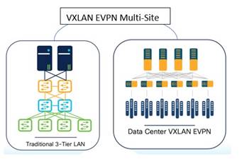
Data Center and Campus Networks
Topologies Supported for VXLAN Fabrics
Topologies with a Single Site and WAN/External Connectivity
Topologies with Top-of-Rack (ToR)
External Connectivity from a VXLAN Fabric
Guidelines for a Data Center VXLAN EVPN Fabric
Hardware and Software Recommendations
External Connectivity Network –
Integration of VXLAN Fabrics with Services like Firewalls and Load Balancers
Migration from Classic LAN to VXLAN Networks
Cisco Nexus Dashboard Fabric Controller (NDFC) provides an enhanced "easy" fabric workflow for unified underlay and overlay provisioning of the Virtual Extensible LAN (VXLAN) Border Gateway Protocol (BGP) Ethernet Virtual Private Network (EVPN) fabric configuration on Cisco Nexus and Cisco Catalyst switches. The configuration of the fabric is achieved using a powerful, flexible, and customizable template-based framework. Using minimal user inputs, you can bring up an entire fabric with Cisco-recommended best practice configurations in a short period of time. The set of parameters exposed in the fabric settings allows you to tailor the fabric to your preferred underlay and overlay provisioning options. This white paper covers the following:
● End-to-end deployment of switches in a VXLAN fabric using the Data Center VXLAN EVPN fabric template created specifically for Cisco Nexus 3000 and Nexus 9000 switches
● Pre-requisites to begin using NDFC
● Supported hardware for this design
This white paper assumes a generic understanding of VXLAN BGP EVPN technology, terminologies, and concepts.
Note: The links to the NDFC documentation within this white paper refer to the NDFC 12.2.1 documentation. For the latest release of the documentation, see the Cisco NDFC User Content Collection page and specify the release version and persona from the drop-down lists.
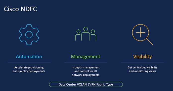
Cisco Nexus Dashboard Fabric Controller (NDFC), formerly known as Data Center Network Manager or DCNM, is the new, power-packed, feature-rich service exclusively available on the Cisco Nexus Dashboard (ND). ND embraces a Kubernetes-based microservices architecture. NDFC provides comprehensive lifecycle management, configuration, and automation for Cisco NX-OS, IOS XE, IOS XR, as well as non-Cisco devices for a myriad of deployments across data center and campus networks.
To begin using NDFC, you first need a Nexus Dashboard cluster. ND is deployed as a cluster of master and worker nodes in a virtual or physical form factor. The type and number of nodes required in a given ND cluster hosting NDFC depends on the scale of managed (or monitored) switches, as well as whether NDFC is used for LAN, SAN or media fabrics. To learn more about ND, see the Cisco Nexus Dashboard.
It is also possible to co-host NDFC with services like Cisco Nexus Dashboard Insights in the same cluster and use NDFC to manage a variety of architectures like classic Ethernet, VXLAN in the data center and campus, eBGP-based routed fabrics (with and without VXLAN), VXLAN Multi-Site, and so on.
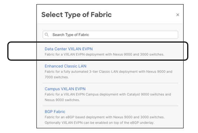
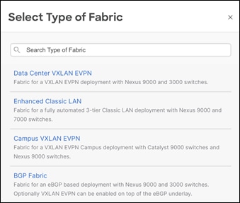
The following is an example of the different types of NDFC fabrics.
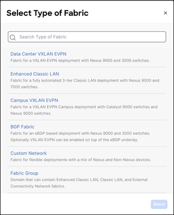
You can select the respective fabric type to start using NDFC fabric templates and let NDFC do the heavy lifting! For more information about NDFC LAN fabric types, see Understanding LAN Fabrics.
Use the Nexus Dashboard Capacity Planning tool to determine the number of ND nodes required for your business needs.
When the ND cluster is formed and healthy, users can determine the deployment mode and select services like Nexus Dashboard Orchestrator and Nexus Dashboard Insights alongside the Nexus Dashboard Fabric Controller. Upon enabling the respective services, the ND cluster intelligently determines the required resources.
A VXLAN fabric with BGP EVPN control plane has proven that it can provide secure multi-tenancy and mobility at scale, both within the same data center as well as across data centers with VXLAN Multi-Site. Below are the major use cases highlighting VXLAN architecture with NDFC.
Greenfield/Brownfield VXLAN - Single Site
You can use NDFC best practice templates to build VXLAN BGP EVPN underlay and overlay networks from scratch (Greenfield). This is applicable for provisioning new VXLAN EVPN fabrics.
You can also use NDFC for Brownfield deployments which are applicable for existing VXLAN EVPN fabrics. This helps with migration of CLI-configured (or managed by automation scripts) VXLAN EVPN fabrics to NDFC using the Data Center VXLAN EVPN fabric template. All intent is learnt by NDFC and configurations on switches is preserved, making this a non-disruptive operation. These can then be incrementally managed and maintained by NDFC.
This use case is discussed at length in this white paper.
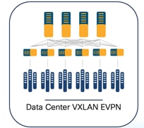
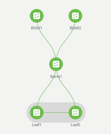
Below is an example of a Clos topology for a Data Center VXLAN EVPN fabric managed by NDFC.
To simplify deployment, NDFC has provided ways in which customers can deploy individual data center fabrics and provide the ability to extend networks and VRFs across fabrics grouped together as part of the same Multi-Site Domain (MSD). An MSD is a multifabric container that is created to manage multiple member fabrics. An MSD is a single point of control for definition of overlay networks and VRFs that are shared across member fabrics. When you move fabrics (that are designated to be part of the multifabric overlay network domain) under the MSD as member fabrics, the member fabrics share the networks and VRFs created at the MSD level. This way, you can consistently provision networks and VRFs for different fabrics, at one go. It significantly reduces the time and complexity involving multiple fabric provisioning. This use case is discussed in the latter section of this white paper.
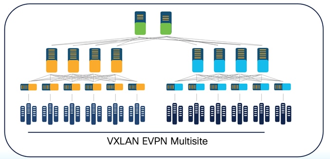
Below is an example of a VXLAN EVPN Multi-Site topology managed by NDFC.
Co-Existence of Classic LAN and VXLAN
This use case describes the co-existence of classic LAN and VXLAN EVPN networks, which is – a hybrid of a virtual port channel (vPC)/spanning tree, Layer 3 tier architecture, and an overlay-based leaf-spine VXLAN architecture, all within the same NDFC cluster. This option is for customers who plan to migrate workloads to an existing VXLAN network but are currently on classic Ethernet. You can leverage NDFC for brownfield import of existing classic networks and manage them incrementally. When ready, you can use NDFC templates to build a VXLAN BGP EVPN underlay and overlay from scratch (greenfield). Once both architectures are up and running, You can use NDFC to migrate your workloads from a classic to a VXLAN network. You can stop using your classic LAN fabric after successfully migrating to VXLAN. For more information on migrating from a classic Ethernet environment to VXLAN BGP EVPN, see Migrating Classic Ethernet Environments to VXLAN BGP EVPN.
Below is an example of co-existence of a classic Ethernet and VXLAN EVPN environment managed by NDFC.
External Connectivity for VXLAN fabrics
External connectivity from a data center is a prime requirement where a data center fabric workload needs to communicate with an outside fabric over WAN or backbone services. To enable Layer 3 for north-south traffic flow, use virtual routing and forwarding instances VRF-Lite peering between data center border devices and the external fabric edge routers.
You can enable VRF-Lite on the following devices:
● Border
● Border Spine
● Border Gateway
● Border Gateway Spine
● Border Super Spine
For more information on configuring VRF Lite, see VRF Lite.
Below is an example of external connectivity from a VXLAN EVPN fabric.

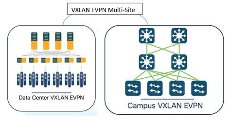
Data Center and Campus Networks
NDFC supports the Data Center VXLAN EVPN fabric type to automate and manage
Data Center VXLAN BGP EVPN networks based on Nexus 9000 and 3000 series switches. Also, NDFC supports the Campus VXLAN EVPN fabric type to automate and manage enterprise campus VXLAN BGP EVPN networks based on Catalyst 9000 series switches.
Optionally, administrators can integrate a Nexus 9000 switch with Border Gateway functionality to interconnect with remote data centers and campus for VXLAN EVPN Multi-Site Layer 2 and Layer 3 extensions.
While this white paper covers a data center- based deployment, you can find information about a campus VXLAN deployment in Campus VXLAN EVPN.
Below is an example of co-existence of VXLAN EVPN fabrics in a Data Center VXLAN EVPN fabric and a Campus VXLAN EVPN fabric.
NDFC provides a fabric template called the Data Center VXLAN EVPN. NDFC uses this template to completely automate the underlay creation of VXLAN BGP EVPN fabrics, as per Cisco best practice templates. This minimizes the learning curve and makes it easy to move to a Software-Defined Networking (SDN)-driven approach, all while preparing for the future by improving scalability by building overlays with VXLAN and offering a wide variety of maintenance and operational features (to be discussed in the Day 2 section).
The following are examples of protocols supported with the Data Center VXLAN EVPN fabric type, keeping in mind Cisco-recommended best practices and configurations as described below.
1. Underlay routing protocols between leaf and spine - Open Shortest Path First (OSPF) and Intermediate System-to-Intermediate System (IS-IS).
2. Note: For eBGP-based VXLAN fabrics, you must select the BGP Fabric type. For more information, see Managing BGB-Based Routed Fabrics.
3. Replication mode for Broadcast, unknown-unicast and multicast traffic (BUM) traffic – multicast and ingress replication.
4. Spines acting as route reflectors (RR) (User can pick between 2 and 4).
5. One-click vPC pairing - The vPC pairing must be done for switches where Layer 3 vPC peer-keep alive is used. NDFC supports vPC peer keep alive with loopback or the management interface. NDFC also supports vPC fabric peering with a virtual peer link.
NDFC’s Data Center VXLAN EVPN template needs very few inputs from the user to get going! At the time of fabric creation, the user must provide the fabric name and BGP ASN number as mandatory fields. All the other fields can be customized or left with default values. Once the fabric has been created and the respective switches have been discovered within this fabric, NDFC learns the topology and how the switches are connected. Users must thereafter specify roles for each switch. After the role definition, NDFC pushes respective configurations using the Recalculate and Deploy GUI option. After this, all configurations can be managed from a single pane of glass with the ability to do rollback at a ticket level with the help of the change control and rollback feature in NDFC. For more information, see Change Control and Rollback.
The above will be covered in the below ‘How to’ section.
Topologies Supported for VXLAN Fabrics
The following roles are supported in NDFC for VXLAN BGP EVPN:
Leaf, Spine, Border, Border Spine, Border Gateway, Border Gateway Spine, Super Spine, Border Super Spine, Border Gateway Super Spine, Top of Rack (ToR)
Below topologies are different variations of the supported topologies and roles in the Data Center VXLAN EVPN fabric.
There are four main variations of Border:
Border Alone, Border Leaf, Border Spine, Border Super Spine
There are four main variations of Spine:
Spine, Super Spine, Border Spine, Border Gateway Super Spine
All of these will be pictorially represented in the topologies below.
Topologies with a Single Site and WAN/External Connectivity
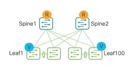
The following topology is supported for both Layer 2 and Layer 3 hosts under a leaf. This is a basic representation of a Clos topology. There will always be WAN/external connectivity.
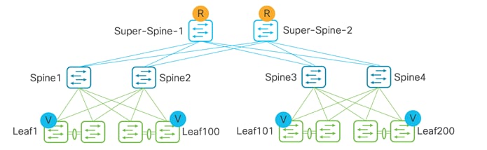
Below is for topologies with a super spine acting as the route reflector (RR), while the spine is used purely for underlay-routed traffic.
When both spine and super spine roles are present in the same VXLAN EVPN fabric, the super spine role allows the Clos architecture by providing RR/Route Processor (RP) functionality while the spine becomes the transit router for end-to-end IP reachability.
Below is for VXLAN end-to-end intra-site traffic. This topology is supported for both Layer 2 and Layer 3 external hosts (towards WAN).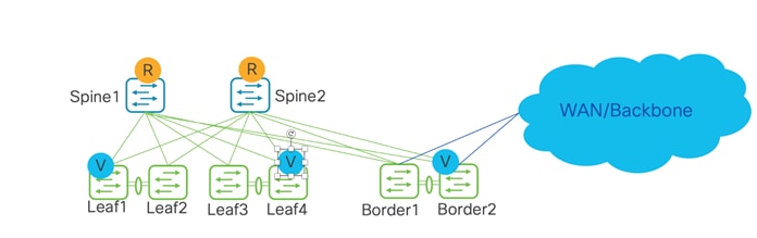
The following topology is a combined spine and border role into a border-spine, with a host towards WAN.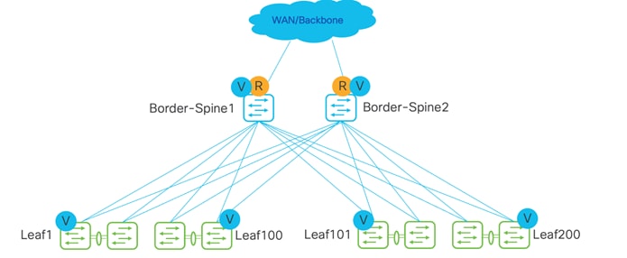
The following topology is for a super spine and border, with a host towards WAN. Borders can be attached only to a super spine. 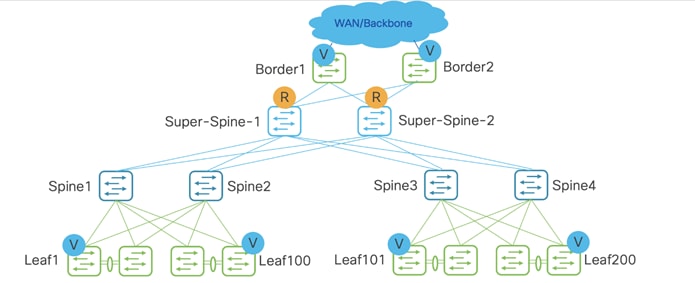
In these topologies, Border Gateway becomes relevant.
Below topology is for VXLAN inter-site traffic, where the hosts are under leafs in a separate Data Center VXLAN EVPN fabric. There can either be a link between Border Gateways (Anycast Border Gateway) or a virtual port channel (vPC) between Border Gateways. Up to six Anycast Border Gateways are supported in a site.
Topology with no vPCs between Border Gateway (Anycast Border Gateway) 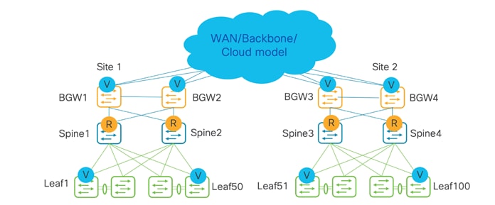
Topology with vPCs between a Border Gateway. Recommendation is to have two pairs of vPC Border Gateways in a site, if possible, to split Layer 2 Virtual Network Identifier (VNIs) across the two pairs for better scale. 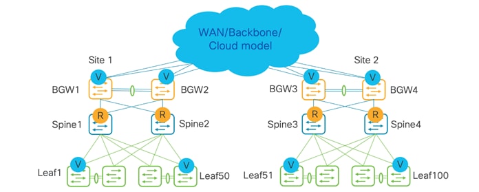
Below topology is for VXLAN inter-site traffic, but with a centralized route server model. A distributed route server is supported as well. 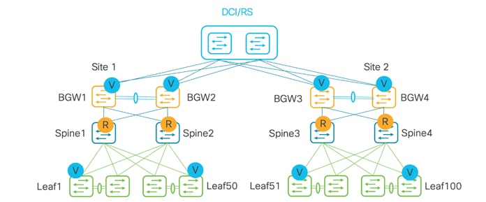
Below topology is for VXLAN inter-site traffic with just Border Gateways. This is called full mesh.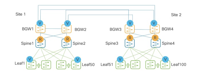
Below topology is for external host towards WAN, with a shared border acting as a VXLAN tunnel endpoint (VTEP) and route server used for the control plane.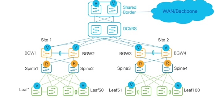
Below topology is for an external host towards WAN, with a combined shared Border Gateway and spine role into a Border-Gateway-Spine, acting as a VTEP and a route server used for the control plane.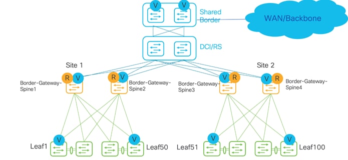
In the below topology, two Sites 1 and 2 are part of an MSD. Super spines and Border Gateways are combined into a Border Gateway super spine, used for Multi-Site. Borders are used for external connectivity.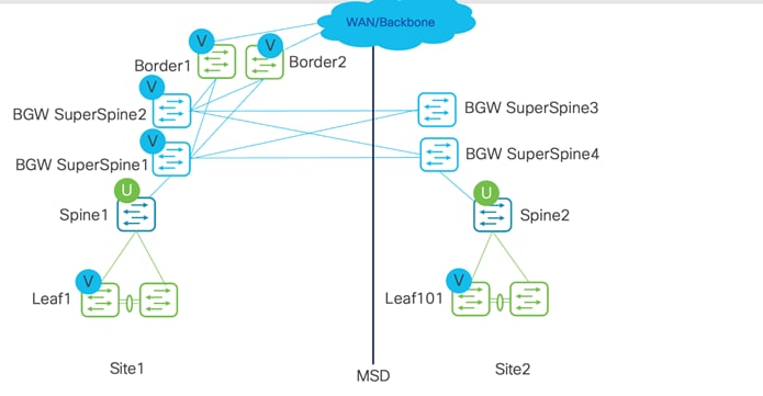
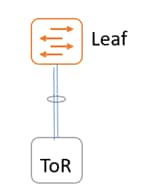
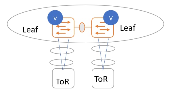
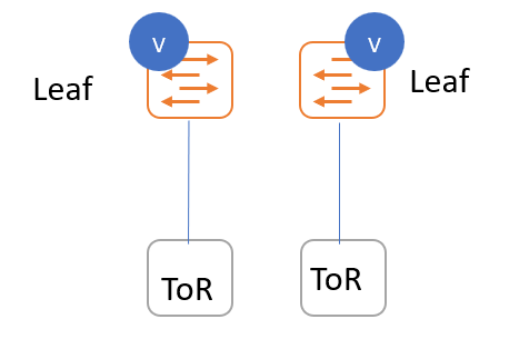
Topologies with Top-of-Rack (ToR)
ToR switch connected to a leaf switch.
ToR switches with port channels connected to leaf switches individually. The leaf switches are in a vPC pair.
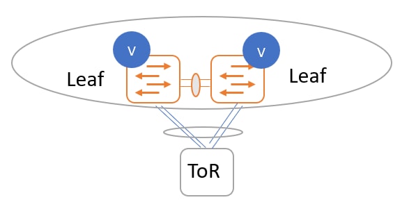
ToR switches with port channels connected to leaf switches individually. The leaf switches are in a vPC pair.
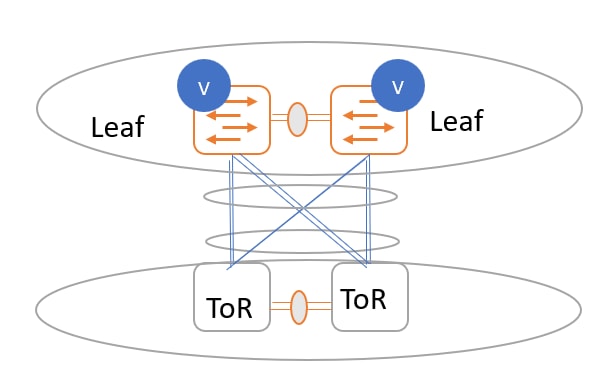
ToR switches with back-to-back vPC connections. The leaf switches and ToR switches are both in vPC pairs.
ToR switches with port channels connected to both leaf switches. The leaf switches are in a vPC pair.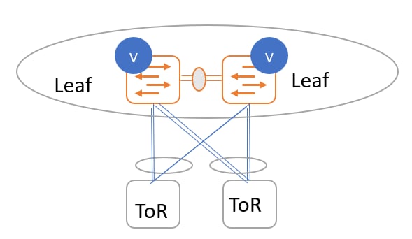
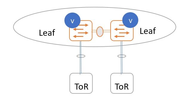
ToR switches with port channels connected individually to leaf switches. The leaf switches are in a vPC pair.
ToR switches with port channels connected individually to leaf switches. The leaf switches are not in a vPC pair.
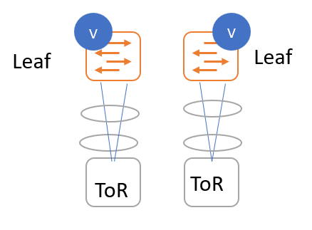
ToR switches without port channels connected individually to leaf switches. The leaf or ToR switches are not in a vPC pair.
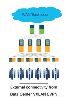
External Connectivity from a VXLAN Fabric
External connectivity from data centers is a prime requirement where workloads that are part of a data center fabric can communicate with an outside fabric over WAN or backbone services. To enable Layer3 for a north-south traffic flow, use virtual routing and forwarding instances (VRF)-Lite peering between data center border devices and the external fabric edge routers. A VXLAN EVPN-based data center fabric provides connectivity by distributing IP-MAC reachability information among various devices within the fabric. Use the VRF-Lite feature for connecting the fabric to an external Layer 3 domain.
You can enable VRF Lite on the following devices:
● Border
● Border Spine
● Border Gateway
● Border Gateway Spine
● Border Super Spine
For more information on the VRF-Lite use case, see VRF Lite.
Below is an example topology of external connectivity from a VXLAN EVPN fabric.
Apart from VRF LITE, seamless gateway protocols such as VXLAN EVPN to SR-MPLS and MPLS LDP L3VPN handoff is also supported for connecting a VXLAN fabric to an external Layer 3 domain.
For more information, see MPLS SR and LDP Handoff.
Guidelines for a Data Center VXLAN EVPN Fabric
For configurations of the below features, refer to the Cisco NDFC User Content Collection page.
● Support for both greenfield and brownfield deployments
● Support for IPv4 and IPv6 for switch discovery as a well as for protocols
● Inband management and inband POAP for supported switches
● Supported Nexus 3000 and 9000 switches for full automation
● One-click vPC pairing
● Interface groups, multi-attach/detach, quick attach/detach, shared policy for switches
● Change control and rollback
● vPC fabric peering is supported from Cisco NX-OS Release 9.2(3)
● IPv6 underlay is supported for the Cisco Nexus 9000 series switches with Cisco NX-OS Release 9.3(1) or higher
● VXLANv6 is only supported for Cisco Nexus 9332C, Cisco Nexus C9364C, and Cisco Nexus modules that end with EX, GX, FX, FX2, FX3, or FXP
● The following features are not supported for a VXLAN IPv6 underlay:
◦ Multicast underlay
◦ Tenant Routed Multicast (TRM)
◦ IS-IS, OSPF, and BGP authentication
◦ VXLAN Multi-Site
◦ Dual-stack underlay
◦ vPC fabric peering
◦ DCI SR-MPLS or MPLS-LDP handoff
◦ BFD
◦ Super spine switch roles
◦ NGOAM
Hardware and Software Recommendations
For NDFC, if starting fresh, Cisco recommends using the latest release of Nexus Dashboard.
A good place to start looking for the right release is the documentation on cisco.com.
A Data Center VXLAN EVPN fabric supports automation of the Cisco Nexus 3000 and 9000 platforms. Cisco recommends using Nexus 3000/9300 switches as VTEP devices in a VXLAN topology.
Use Nexus modular platforms like 9500 platform switches (or switches in other platforms that provide the same or similar port density and performance) as the spine (or aggregation-layer) devices in the underlay network. However, there is no mandate on the number of platforms per layer.
For the exact features supported for the respective Nexus 3000 and 9000 platforms, see the Nexus Switch Platform Support Matrix.
Use the Recalculate & Deploy option to build new intent in NDFC based on the discovered topology and how the switches are connected, roles of the switches, and how the fabric settings are defined. Recalculate & Deploy is at a fabric level – every time it runs, it runs for all the switches in the fabric. The recalculate operation can be expensive depending on the scale of the fabric and how often it is executed. The only time it is recommended to do so is when new switches or links are added, when fabric settings are edited, or when vPC or ToR associations are changed.
Configuration Compliance (CC) is applicable for all switches managed by NDFC. In NDFC, switches can either be in managed mode or monitor mode. When monitored, no configurations are pushed from NDFC. When in managed mode, NDFC is the control point for all configurations that reside in the switch. NDFC allows a user to access the CLI of the switch.
If the running configuration deviates from the NDFC user intent defined, this is flagged, and the switch is marked as Out-of-Sync. This can be either a pending change that hasn’t been pushed from NDFC, or an out-of-band change made using the CLI or a script. To bring NDFC back in sync, the user needs to deploy these pending changes that will be displayed in NDFC. The configuration compliance module keeps track of this deviation and checks if the running configuration complies with the user intent periodically in NDFC.
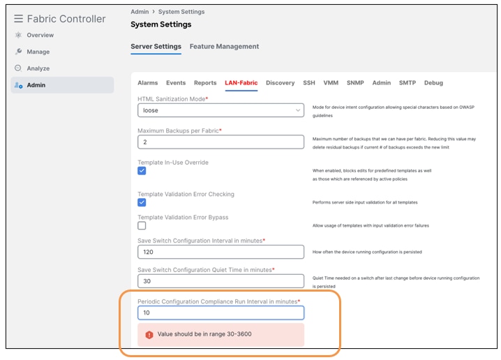
Configuration Compliance (CC) Demo
CC runs by default once every day, but you can customize CC to run every 30 minutes to 3600 minutes.
NDFC ships a variety of out-of-box policies called templates that you can use for configuring everything in VXLAN EVPN, including configurations for an underlay or an overlay. NDFC has various workflows that leverage these templates internally to make complex configurations seamless to the user. You can use these templates individually or as a group to define a requirement for a switch or a group of switches or an interfaces
You can add, edit, or delete templates that are configured across different Cisco Nexus, IOS XE, IOS XR, and Cisco MDS platforms. Templates support JavaScript. Use JavaScript functions in a template to perform arithmetic operations and string manipulations in the template syntax. NDFC also supports CLI templates that consist of CLI- level commands in a template form.
NDFC also supports freeform policies that are CLIs as seen in the running configuration. NDFC allows users to simply paste freeform policies for different objects like a fabric, switches, group of switches of a certain role (Leaf/Spine), AAA configurations, bootstrap configurations, interfaces, networks, VRFs, and so on. For brownfield import, while most of the switch configuration is mapped to a pre-defined NDFC policy, certain configurations go under a freeform block like queuing policies, QOS, prefix lists and so on that you can edit like all other configurations.
These out-of-box, custom, and freeform policies provide a lot of flexibility to the user to push configurations from NDFC.
When defining any intent for a switch or a group of switches, a user either utilizes a workflow in NDFC or uses a pre-defined, custom, or a freeform policy for a specific purpose. NDFC converts the user intent to commands, which are then ready to be pushed out. However, NDFC doesn’t push these user intents out by default. NDFC marks the switch as Out-of-Sync, which means there is intent defined in NDFC that is not in the running configuration of the switch. NDFC then generates a Preview for the user to evaluate and assure the user intent is per their requirement. Once the user acknowledges the generated set of commands, the changes can then be deployed based on user action. This flow is called a Save-Preview-Deploy. This gives full control to the user to deploy changes only when the generated commands comply with the user intent. Once the changes are deployed, the switch is then put back In-Sync. This flow is followed for any Day 0-1-2 feature in NDFC.
NDFC supports various fabric types for a variety of deployments. These fabric types encompass complex built-in templates to make provisioning of deployments easy for end users. Depending on the kind of network architecture, brownfield or greenfield requirements, the kind of switches in these networks, users can select any of the following supported fabric types in NDFC:
Fabric for a VXLAN EVPN deployment with Nexus 9000 and 3000 switches (this fabric type is the focus of this white paper). Supports greenfield and brownfield deployments
Fabric for a fully automated 3-Tier Classic LAN (access-aggregation-core) deployment with Cisco Nexus 9000, 3000, and 7000 switches. Supports greenfield and brownfield deployments
Fabric for a VXLAN EVPN campus deployment with Catalyst 9000 switches. Supports Greenfield deployments
Fabric for an eBGP-based deployment with Nexus 9000 and 3000 switches. Optionally, VXLAN EVPN can be enabled on top of the eBGP underlay. Supports a greenfield deployment.
Fabric for custom deployments with a mix of Nexus and non-Nexus devices. Supports greenfield and brownfield deployments.
Domain that can contain Enhanced Classic LAN, Classic LAN, and External Connectivity Network fabrics.
Fabric to manage a legacy Classic LAN deployment with Nexus switches. Supports greenfield and brownfield deployments.
Fabric for monitoring Nexus switches for basic discovery and inventory management.
Domain that can contain multiple VXLAN EVPN Fabrics (with Layer 2/Layer 3 overlay extensions) and other fabric types.
Fabric to manage or monitor existing Nexus 9000 switches in an IP Fabric for Media Deployment (IPFM).
Fabric for a fully automated deployment of IPFM with Nexus 9000 switches.
Fabric to interconnect VXLAN EVPN for Multi-Site deployments with a mix of Nexus and non-Nexus devices
External Connectivity Network –
Fabric for core and edge router deployments with a mix of Nexus and non-Nexus devices. Supports greenfield and brownfield deployments.
For more information, see Understanding LAN Fabrics.
The requirements to start provisioning VXLAN networks are described in this section. At least one ND cluster is mandatory before other operational/setup steps.
● Nexus Dashboard (virtual or physical) nodes to form a cluster
Use the Nexus Dashboard Capacity Planning guidelines for finding the number of nodes per form factor and the supported scale.
The cluster nodes can be Layer 2 or Layer 3 or adjacent on the data interface.
We recommend having a standby node for HA purposes.
For more information, see the Cisco Nexus Dashboard Deployment Guide.
● Nexus Dashboard Fabric Controller (NDFC)
One an ND cluster is deployed, enable NDFC. For more information, see the Cisco Nexus Dashboard Fabric Controller Deployment Guide white paper.
● Reachability between NDFC service and the switches to be managed
NDFC supports out-of-band (OOB) and inband management of switches for VXLAN fabrics. Users must decide if they want to manage their switches using the management or data connections.
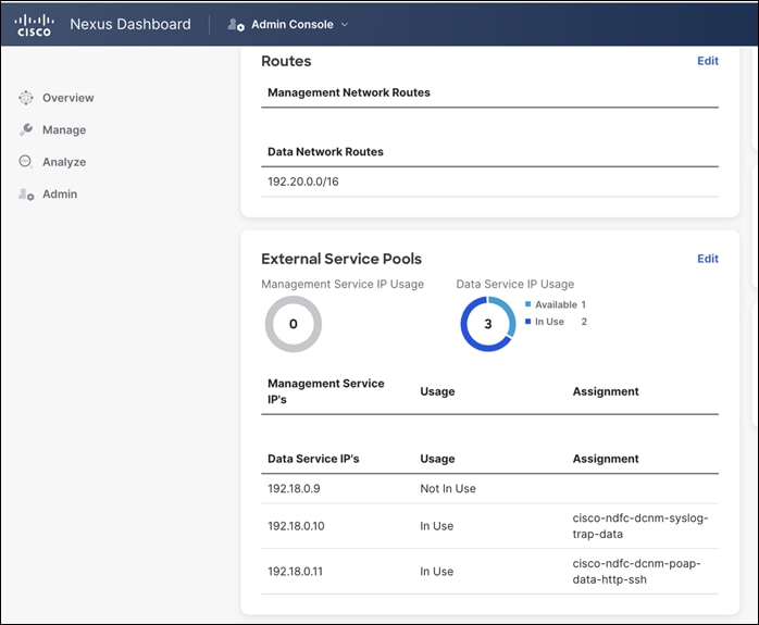
Define the appropriate routes for reachability of the switches from the ND cluster under Admin > System Settings. Specify the external service pools for SNMP and POAP over the management or data subnet during ND cluster bring up. You can always edit the external service pools settings by navigating to Admin > System Settings in NDFC.
![]()
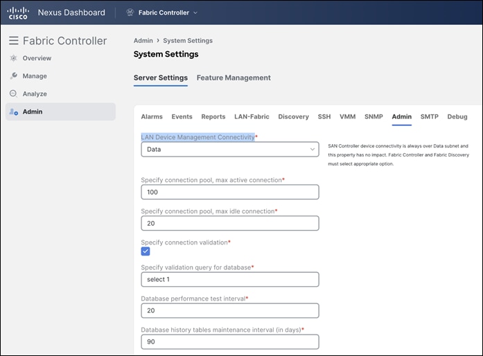
NDFC LAN device management connectivity in Admin > Server Settings is set to Management by default. Consequently, the SCP-POAP and SNMP-trap service pods will be spawned with external IPs associated with the Nexus Dashboard Management subnet. This can be changed to Data as well. To change the default option, navigate to the LAN Device Management Connectivity option in NDFC, which is found under Admin > System Settings > Server Settings > Admin.
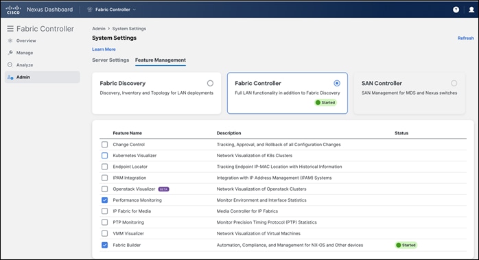
● Feature management within NDFC
Fabric Builder (at the very minimum)
Performance Monitoring (optional) for SNMP-based performance monitoring (CPU, memory, traffic, temperature, interface, links) at the switch level
● Fabric type to use
Data Center VXLAN EVPN
● Switches and roles that can be managed in a VXLAN fabric
Cisco Nexus 3000 or 9000 series switches
This section describes creating a Data Center VXLAN fabric, adding switches to the fabric, defining roles for the fabric, and creating a vPC.
A fabric refers to a container of switches that share attributes defined at the fabric level. NDFC supports creating a Data Center VXLAN EVPN fabric for one such container. There can be multiple fabrics active at the same time. VXLAN fabrics can talk to each other using VXLAN EVPN Multi-Site.
This white paper describes the following topologies:
● Two leaf switches in a vPC pair
● A spine
● Two Border Gateways
We will configure these using the NDFC Data Center VXLAN EVPN fabric type.
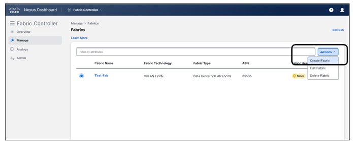
Below is the workflow you would use to bring up a fabric and add switches to it.
Step 1. Create Fabric
Step 2. Discover Switches in the Fabric
Step 3. Bootstrap (Power-On Auto Provisioning)
Step 4. Define Roles
Step 5. vPC pairing
Step 6. Interfaces
Step 7. Recalculate and Deploy
Let’s discuss these steps in detail.
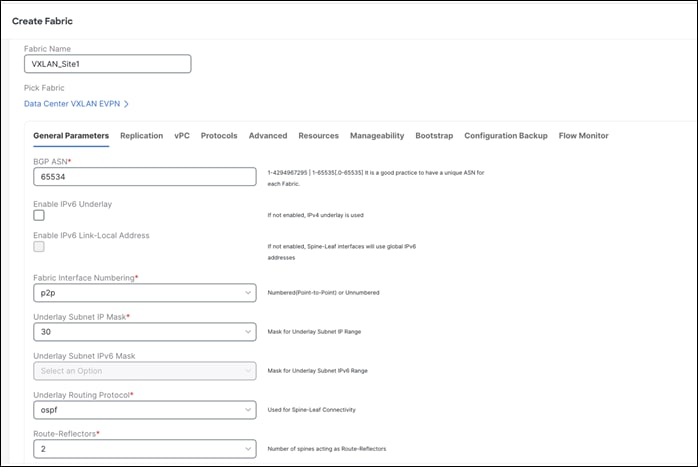
The very first step is to create a fabric using the Data Center VXLAN EVPN template as shown below. The fabric-level template helps define parameters that apply to respective layers of the network and the fabric as a whole. This step is to build the VXLAN underlay. Creation of an IPv4 and an IPv6 underlay is supported.
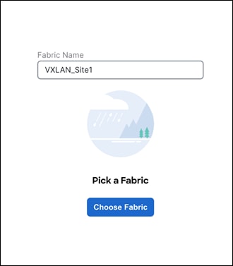
Once the fabric template is selected, optionally customize fabric-level settings or leave them as the default settings. All the fields have a default, with optional parameters that allow users to change them, all per Cisco best practices.
The only mandatory fields are the following:
◦ Fabric Name
◦ BGP ASN
Note: In this section, we will discuss creating a VXLAN EVPN fabric with an IPv4 underlay. For information on how to configure a VXLAN EVPN fabric for IPv6, see the section Configuring a VXLANv6 Fabric here.
The following screen shot displays the General Parameters tab where you just need to configure a BGP ASN number.

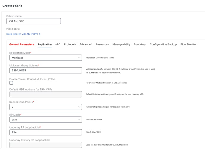
The following screen shot displays the Replication tab where Multicast is the default value for the Replication Mode field.
You can customize the vPC default values.
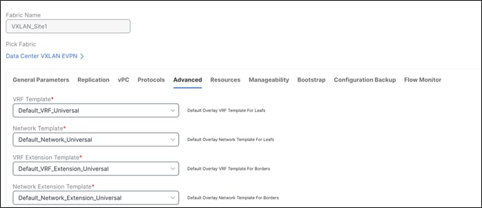
Other tabs available for customizations:
◦ Protocols for OSPF and IS-IS
◦ Advanced for Overlay Mode, PVLAN, CoPP profile, enable features like VXLAN OAM, CDP, queueing policies as well as group freeform config for Leaf/Spine/ToR switches
◦ Resources for the default IP, Subnet, VNI, VLAN, VRF-Lite deployment parameters etc.
◦ Manageability for DNS, NTP, Syslog server settings
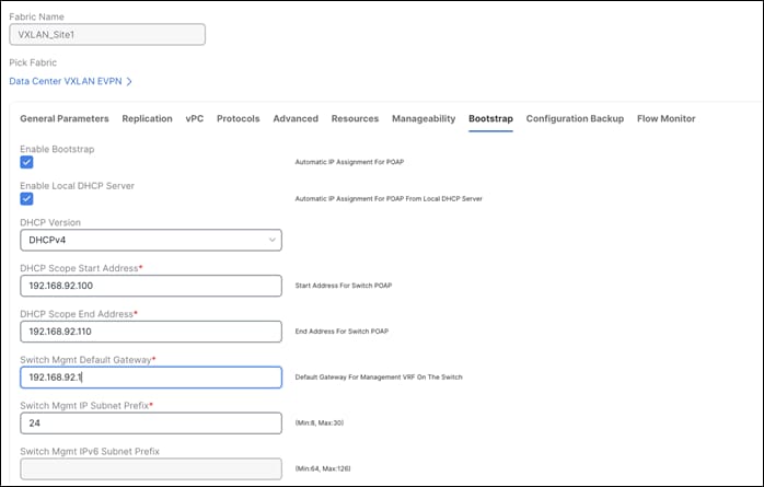
◦ Bootstrap for POAP and DHCP server settings – Use this option to enable POAP at the fabric level.
◦ Configuration Backup to define cadence of automatic fabric-level backups
◦ Flow Monitor to enable Netflow
Note: Once you create a fabric, you cannot edit the Fabric Name field, as there may be an existing network linked to that fabric.
For more information, refer to the section Creating a VXLAN EVPN fabric Using the Data Center VXLAN EVPN Template here.
2. Discover Switches in the Fabric
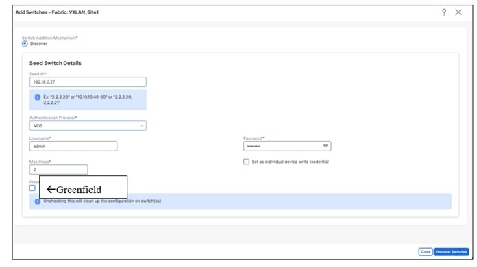
Once you create the fabric, you can import switches using the Add Switches page and supplying the necessary credentials. Make sure reachability exists between NDFC and these switches. The value for the Seed IP field can be the management IP of the switch. Both out-of-band and inband management of switches is supported for this fabric type.
‘Preserve Config = NO’ indicates a greenfield import. All existing configurations except the management IP, Default Gateway, and Boot Variables will be erased for fresh configurations to be pushed from NDFC going forward. All switches can now be managed from scratch.
In case of a greenfield addition of a Nexus 3000 or 9000 switch, by default, NDFC learns the basic intent from the switch, performs a write erase, and reloads followed by restoration only of the basic intent on that switch.
‘Preserve Config = YES’ indicates a brownfield import. All existing configurations will be preserved.
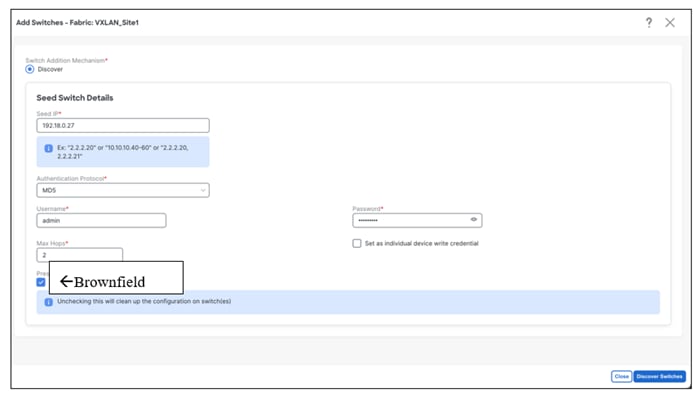
![]()
In a Data Center VXLAN EVPN Fabric with brownfield import, all configurations in the switches are learnt (and preserved) and captured in NDFC. Thereafter, the switches can be incrementally managed from NDFC. The prerequisite is that the fabric and the imported switches must be a fully functional fabric with configurations per Cisco best practices. It is recommended to take a backup of the switch configurations and save them before migration.
The guidelines for brownfield are the same as listed above. That is, it adheres to Cisco best practices and recommendations prior to import. In addition, for a brownfield import, the following guidelines are applicable:
◦ Brownfield import must be completed for the entire fabric by adding all the switches to the NDFC fabric
◦ The cdp format device-id <system-name> command to set the CDP device ID is not supported and will result in an error when adding switches during a brownfield import. The only supported format is cdp format device-id <serial-number> (the default format).
◦ On the Create Fabric page, the Advanced > Overlay Mode fabric setting decides how the overlays are migrated. If the config-profile is set, then the VRF and network overlay configuration profiles are deployed to the switches as part of the migration process. In addition, there will be diffs to remove some of the redundant overlay CLI configurations. These are non-network impacting.
◦ From the Overlay Mode drop-down list, if a CLI is set, then VRF and network overlay configurations stay on the switch as-is with no or little changes to address any consistency differences. Overlay mode is discussed in the Day 1 for VXLAN section.
◦ Brownfield migration of configuration profiles is supported for the Data Center VXLAN EVPN fabric template.
◦ Brownfield migration with switches having a combination of VXLAN overlay configuration profiles and regular CLIs is not supported. If this condition is detected, an error is generated, and migration is aborted. All the overlays must be with either configuration profiles or regular CLIs only.
◦ Brownfield import in NDFC supports the simplified NX-OS VXLAN EVPN configuration CLI.
◦ The following roles and features are unsupported:
o Super Spine
o ToR
o eBGP underlay
o Layer 3 port channel
◦ No configuration changes must be made to the switches until the migration is complete. Otherwise, significant network issues can occur.
◦ Migration to NDFC is supported for both Nexus 3000 and 9000 switches.
◦ Each VXLAN fabric settings must match existing configurations:
o Same values (BGP AS Number, OSPF, and so on) are considered as reference points to your existing fabric, and the values you enter must match the existing fabric values.
o For some fields (such as IP address range, VXLAN ID range), the values that are auto populated or entered in the settings are only used for future allocation. The existing fabric values are honored during migration.
o Some fields relate to new functions that may not exist in your existing fabric (such as advertise-pip). Enable or disable it as per your need.
o At a later point in time, after the fabric transition is complete, you can update settings if needed.
For more information, see the Data Center VXLAN EVPN Configuration Guide.
Once this is done, users must run a Recalculate and Deploy (R&D) for the fabric as described below.
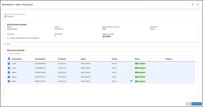
Once the switches are discovered, NDFC shows a list of switches and users can select the appropriate switches to add them to the fabric. Depending on whether this is a greenfield or a brownfield import, NDFC will perform specific actions as described above.
3. Bootstrap PowerON Auto Provisioning (POAP)
To automate the process of upgrading software images and installing configuration files on switches that are being deployed in the network for the first time, POAP can be done from NDFC. Both inband and out-of-band POAP is supported for switches in a VXLAN fabric type. Both IPv4 and IPv6-related POAP options are supported. NDFC can be the local DHCP server providing a management IP and a default route for reachability when the switch is bootstrapped. The desired startup configurations and optionally an image to boot the switch with can be pushed in addition. Alternatively, an external DHCP server is supported as well.
The POAP Process
When a new Cisco NX-OS device is powered on, typically that device has no startup configuration or any configuration state for that matter. Consequently, it powers on with NX-OS and post initialization, goes into a POAP loop. The device starts sending out DHCP requests on all the interfaces that are up including the mgmt0 interface. Any DHCP server can respond to this request. The server providing the DHCP offer is printed in the POAP logs in the switch. As long as there is IP reachability between the device and NDFC, the DHCP request from the device, will be forwarded to NDFC (In this case, let’s consider NDFC to be the local DHCP server reachable from the switch).
For easy Day-0 device bring-up, the bootstrap options should be enabled on the fabric settings.
The POAP script on the switch will try to download the startup configuration, which will not be provided by NDFC until the switch is bootstrapped from NDFC. The switch will keep downloading the script, fail, and repeat until the switch is provisioned in NDFC. In the meantime, NDFC will hand out temporary management IPs and a default gateway to the switch (as defined in fabric settings). Once bootstrapped, the temporary management IP will be replaced with the management IP provided for each switch by the user.
After the added switch completes POAP, the topology page is refreshed with the added switch, thereby depicting its discovered physical connections. Users must then set the appropriate role for the switch followed by a Recalculate & Deploy. The fabric settings, switch role, the topology, and so on are evaluated by NDFC and the appropriate intended configuration for the switch is generated as part of the Save operation. The pending configuration provides a list of the configurations that need to be deployed to the new switch to bring it in-sync with the intent.
You can pre-provision switches as well. The pre-provisioned devices support the following configurations in NDFC:
• Base management • vPC pairing • Intra-fabric links • Ethernet ports • Port-channel • vPC • ST FEX •AA FEX • Loopback •Overlay network configurations
From Cisco NDFC Release 12.1.1e, for pre-provisioned and bootstrap switches, dummy values can be added for the serial number. After configuring the network successfully, the serial number can be changed with the appropriate number of the switch on the Switches tab.
POAP in NDFC
The first most important step is to check the Enable Bootstrap check box in fabric settings and optionally check the Enable Local DHCP Server check box (NDFC as a DHCP server), as well as define the subnet scope and default gateway that will be used temporarily while the switch is in its POAP loop once it has been powered up.
Under the specific fabric, Add Switches > Bootstrap will show the switches in the POAP loop. Note, at this point, only temporary management IPs are handed out by NDFC to the switches.
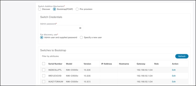
To bootstrap the switches and send the startup configuration from NDFC to the switch, you must enter an admin password. You must edit the required details per switch, that is, the mgmt0 IP (this will be the permanent management IP), hostname, switch role (leaf/spine, and so on) and, optionally, an image policy to boot the switch with.
Once all the details are entered and the user clicks Import Selected Switches, the switches will receive the respective startup configuration from NDFC and the temporary mgmt0 IP will be replaced with the one entered in this step. After this step, the bootstrap switches will be seen under the Switches tab with Config Status as NA but the roles defined. To inherit fabric settings, the switches must be selected and a Recalculate and Deploy be performed. The preview is generated, which can be reviewed, and the configurations can be pushed out if everything looks accurate.
For out-of-band POAP, see Add Switches for LAN Operational Mode.
For inband POAP, refer to the Zero-Touch Provisioning of VXLAN Fabrics Using Inband POAP with NDFC white paper.
From this section onwards, we will cover switches imported using seed IPs and not POAP.
Once the switches are imported, we can begin defining our intent. For example, what do we want this switch to be? Based on the role defined, appropriate configuration will be generated and pushed to the switches by NDFC. NDFC will also discover how the switches are connected and the respective topology to bring up the network.
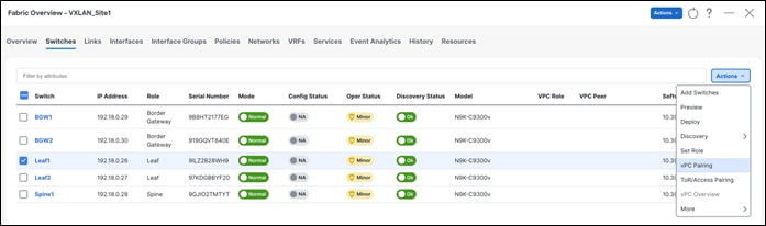
The following section describes how you define roles. The default role is Leaf. We will change the role to Spine and Border Gateway.
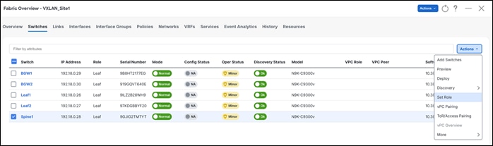
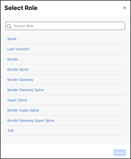
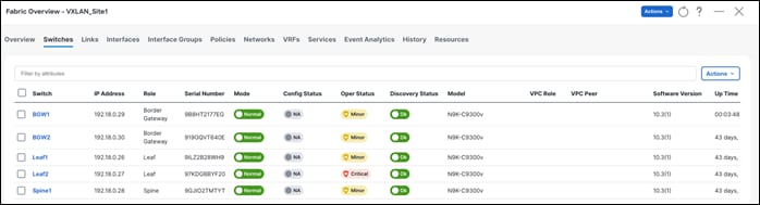
Once you select the appropriate role, the switches reflect the role as below. At this point, no configurations are pushed out. Once the user does a Recalculate and Deploy, configurations can be previewed and deployed.
Once the roles have been defined, the user can pair vPCs using one-click vPC pairing. vPC pairing is supported for both Leaf and Border Gateway roles.
On a Recalculate & Deploy (R&D), NDFC detects the connectivity between the vPC pairs and generates appropriate configurations based on the supported topologies.
For vPC pairing, the default option is to use the mgmt0 interface of the switches as the vPC Peer Keep Alive (PKA) link. However, if the user configures a dedicated Layer 3 link for a vPC PKA, that will be honored by NDFC.
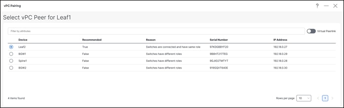
Leaf vPC Pairing
Once you select the leaf switch for vPC pairing, NDFC shows the recommended devices for vPC pairing.

Note: Virtual peer link or fabric peering for vPC is supported in NDFC. vPC fabric peering provides an enhanced dual-homing access solution without the overhead of wasting physical ports for a vPC peer link. This feature preserves all the characteristics of a traditional vPC. However, if a lot of traffic is expected between leaf pairing due to orphan port connectivity, then a physical peer link could be beneficial over vPC fabric peering.
You can convert a physical peer Link to a virtual one. The configuration steps are documented here under the section Creating a Virtual Peer Link.
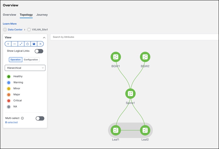
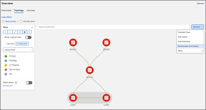
To visualize the pairing, navigate to the NDFC Topology page. As seen below, Leaf1 is paired with Leaf2 based on user intent. This is the ‘operation’ view of the fabric that reflects the health of the switches and the respective links.
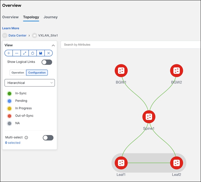
Note: The configurations have not been pushed yet. Only the intent has been defined. Hence, in the Configuration view, the switches still show as RED, which means configurations are pending to be pushed. The switches are Out-of-Sync, that is, the running configuration in the switch doesn’t match the intent in NDFC. Once a Recalculate and Deploy is done, the switches will come back as In- Sync provided there are no errors.
Once the switches have been given their desired roles and vPCs have been created, users can navigate to interfaces for a variety of functions as described.
◦ Create, deploy, view, edit, and delete a port channel, vPC, Straight-through FEX, Active-Active FEX, loopback, and subinterface
◦ Create breakout and unbreakout ports
◦ Shut down and bring up interfaces
◦ Rediscover ports and view interface configuration history
◦ Apply host policies on interfaces and vPCs. For example, int_trunk_host, int_access_host, and so on.
◦ View interface information such as its admin status, operation status, reason, policy, speed, MTU, mode, VLANs, IP/Prefix, VRF, port channel, and the neighbor of the interface.
Below is an example of all the discovered interfaces and the associated policies. For a brownfield import, NDFC learns the configurations on interfaces and maps them to the respective policy that can be edited by the user.
Interface Groups
An interface group consists of multiple interfaces with the same attributes. You can create an interface group that allows grouping of host-facing interfaces at a fabric level. Specifically, you can create an interface group for physical Ethernet interfaces, Layer 2 port channels, and vPCs. You can attach or detach multiple overlay networks to the interfaces in an interface group.
Shared Policy
From Cisco NDFC Release 12.1.2e, you can create and add a shared policy for an interface group. This policy ensures updates of appropriate configurations for all the interfaces in the interface group. In the shared policy, all the interfaces have the same underlay and overlay attributes. When you change the configuration in the shared policy, then that configuration is applied to all the interfaces.
For more details, see Add Interfaces for LAN Operational Mode.
Once the intent has been defined with respect to fabric, roles and vPC, NDFC needs a Recalculate and Deploy (R&D), which means NDFC starts calculating the configurations required for each switch in the fabric. On doing so, NDFC considers the fabric as well as switch intent, shows a preview of the configuration to the user, which once approved, can be deployed.
In case of a brownfield import, when R&D is performed, as part of the process, NDFC performs various pre-checks on the switches such as the following:
◦ vPC consistency checks that should indicate CONSISTENT on the vPC pairs.
◦ Various topology checks will be performed to ensure that the current deployment being imported into the fabric is supported. If any other topology is discovered, an appropriate error is displayed to the user.
◦ Protocols configured in fabric settings must match what is configured on the switches.
Note: On a successful brownfield import, NDFC learns the following: (These can be incrementally managed from NDFC.)
All vPC pairing related information, including the vPC domain, the vPC Peer Keep Alive (KPA), the vPC peer link are learnt for all the applicable switches. All interface-related configurations are learnt. This includes Access, Trunk, Routed, Subinterface, PortChannels, vPCs, and so on. The port channels or vPCs are appropriately mapped to the uplink_access policy. In addition, to the network, VRF attachments, and VRF-Lite related configurations are also learnt. The NDFC Resource Manager has the appropriate accounting of various resources used on the switches, including but not limited to, VLANs, port-channel IDs, vPC IDs, loopback IDs, and so on.
Below are the steps for performing a Recalculate and Deploy.
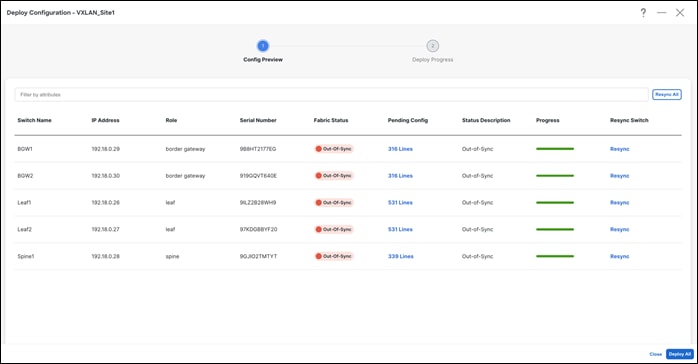
Step 1 - Recalculate and Deploy
Step 2 – Preview Configuration
The configuration is intended for a greenfield import versus a brownfield import.
The following is an example of pending leaf configuration.
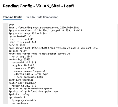
The following is an example of pending spine configuration.
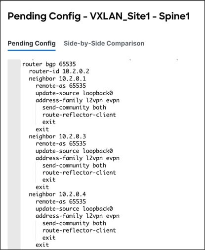
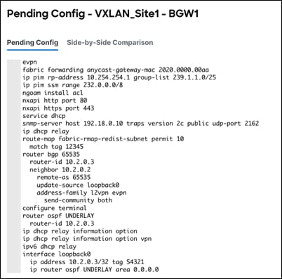
The following is an example of pending Border Gateway configuration.
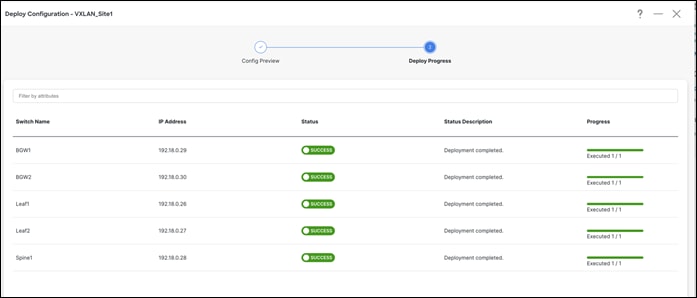
Step 3 – Deploy and Make Sure Configuration Status is In-Sync
NDFC shows a Resync option in the deploy screen. Here is the difference between Resync and Recalculate & Deploy.
Resync is used to pull a new ‘show run’ from the switch and update the Sync status for individual switches or fabrics.
Recalculate & Deploy is used to build new intent (controller functionality) based on the current topology, roles, or fabric settings. This is per fabric only. A recalculate operation is expensive. We recommend doing a Recalculate & Deploy operation when adding new switches or links, or when you change vPC or ToR associations.
Hereafter, Configuration Compliance (CC) kicks in. Any deviation from what is intended by NDFC is flagged and the switch is marked as Out-of-Sync.
Day 1 refers to the definition and attachment of overlays, that is, networks and VRFs. This allows traffic to be encapsulated and sent between endpoints attached to the fabrics defined as part of the Day 0 bring up.
Once the fabric with the appropriate switches has been created and the VXLAN underlay network is up and running, it’s time to deploy networks and VRFs and provision VRF Lite. Both IPv4 and IPv6 options are supported.
Multiple configuration pieces go together when you create a VXLAN network, such as VXLAN VLAN, Anycast SVI, Tunnel interface, EVPN route target, and more. A ‘config-profile’ allows you to bundle all these configurations, so you don’t have to worry about any missing or dangling configurations. With CLI mode, everything is deployed in an NX-OS CLI hierarchical way. A CLI knob was introduced with NDFC 12.0.1a primarily to target and simplify VXLAN brownfield deployments where users don’t have to convert their existing CLIs to profiles.
You can create a VRF or network in CLI or config-profile mode defined at the fabric level. You can only change overlay mode before deploying overlay configurations to the switches. You cannot change the mode after the overlay configuration is deployed unless you remove the VRF and network attachments first.
For a brownfield import, if running configurations in existing switches for overlays are based on config-profiles, you must select ‘config-profile’ as the overlay mode during fabric creation.
However, if the overlays are deployed as CLIs in existing switches, you can import the overlays in either config-profile or CLI modes. You must select the appropriate mode during fabric creation.
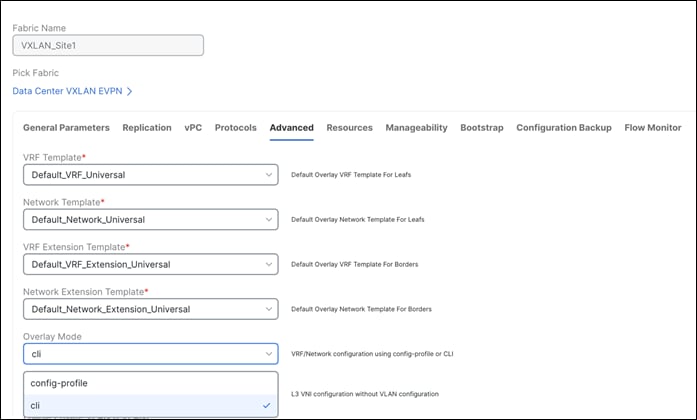
You set Overlay Mode under fabric settings as shown in the following screen shot.
For a brownfield network, the existing networks are retained with a suffix of Auto.
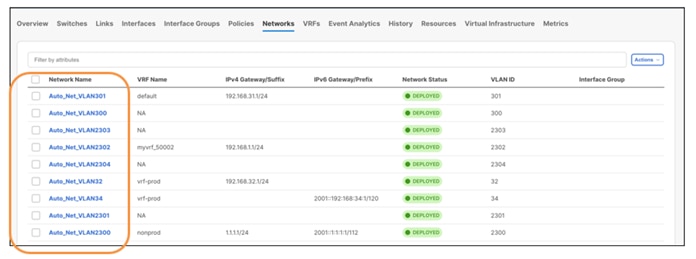
NDFC learns and retains the existing VRFs as well.

An edit operation for learnt networks and VRFs is always possible using NDFC. The existing configurations get mapped to a pre-defined template providing an intuitive workflow to make further changes using the Actions > Edit operation.
Next, let’s look at creation of new networks and VRFs. This is applicable for both brownfield and greenfield networks.
For more information on creating networks and attaching VRFs, refer to the section Overlay mode here.
Day 1 workflows fall in the below categories:
● VRF-Lite
Various templates (as seen under the Advanced tab of each fabric) are shipped with NDFC to incorporate all above use cases with minimal user input.
Note: Network and VRF Name are auto populated on creation. NDFC also has an option of Propose VLAN for networks and VRFs. You can customize all of these fields. All these parameters are also tracked in the NDFC Resource Manager that keeps a database of used resources to avoid conflicts.
A Layer 2 network is easy to create. The gateway for a Layer 2 network resides outside of the fabric. You can leave the IP address of the gateway empty. You can input an associated VLAN or let NDFC propose a VLAN (Propose VLAN option) based on the available resources (the range is customizable in fabric settings). There is no VRF in case of a Layer 2 network.
Once you create networks, you can attach host-facing ports on the leaf.
Step 1 - Create a Network
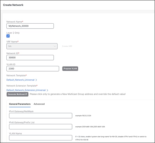
Settings on the Advanced tab include enabling the ARP Suppression option (not supported for a Layer 2 only network), enabling Netflow, adding DHCP relay server information, and so on.
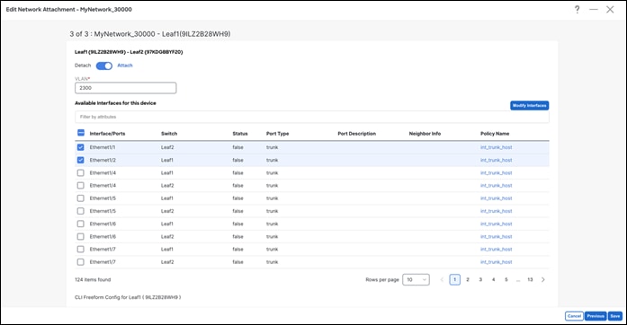
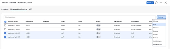
Step 2 - Attach a Network
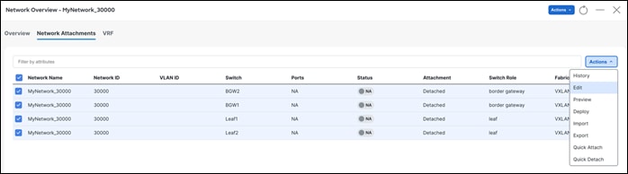
After clicking Actions > Edit, NDFC displays options to attach the selected network to interfaces for switch roles of leaf, border gateway, and other roles. These are all the supported roles associated with deploying a network. Only trunk or access interfaces are seen in the list. You can associate networks to interface groups (a group of interfaces with the same attributes). You can attach or detach multiple networks to an interface group. An interface group consists of Ethernet interfaces, Layer 2 port channels and vPCs. For more information, see Add Interfaces for LAN Operational Mode.
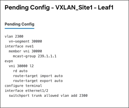
Step 3 – Review Pending Configurations
This includes creating the VLAN and associating it to the Virtual Network Identifier (VNI) of the network, allowing the VLAN on the host-facing port on the leaf, and creating a Network Virtual Interface (NVE) interface, which is member of the VNI.
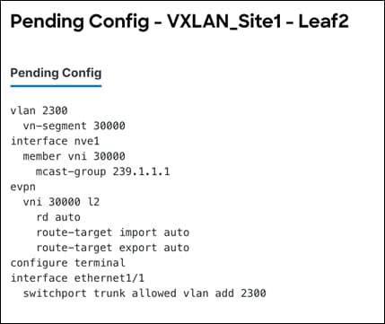
The following output shows the pending configurations for leaf1 and leaf2.
The following output shows the pending configurations for leaf2.
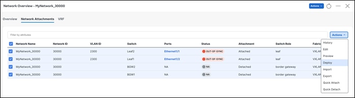
Step 4 – Deploy Configuration

2. Layer 3 Network with a Custom VRF
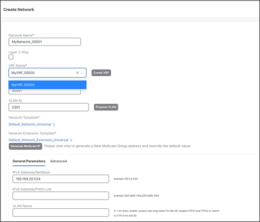
You can create a Layer 3 network for a custom VRF. First, create a new VRF using the Default_VRF_Universal template.
Step 1 – Create VRF
NDFC pre-populates the VRF Name and VRF ID that can be changed later. The VLAN ID is the corresponding tenant VLAN for the network. You can enter an ID or ask NDFC to propose a new VLAN for the network.
All the fields in the General Parameters and the Advanced tabs are explained in the section Overlay Mode here.
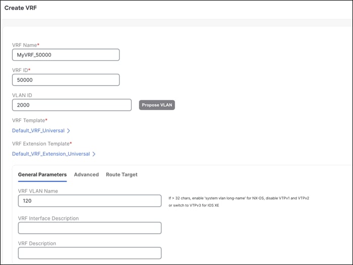
You can enable or customize several VRF-level parameters using the Advanced tab, including enabling Tenant Routed Multicast (TRM).
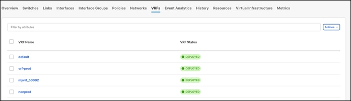
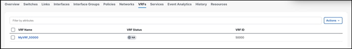
Once you create the VRF, VRF Status displays as NA since you haven’t deployed the VRF yet.
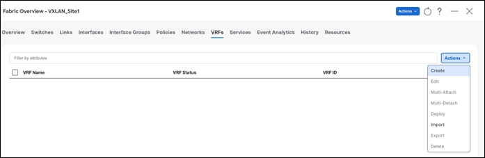
Once you create the VRF, you can map it to a Layer 3 network. Follow the procedure below to map a VRF to a Layer 3 network.
Step 1 - Create Network
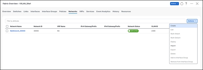
Created VRFs display on the Fabric Overview > Networks page. After selecting a VRF, you can choose various actions from the Actions drop-down list. You can select the desired VRF for the corresponding Layer 3 network, define a VLAN, and an IPv4 or an IPv6 gateway at the very minimum. You can customize all of the fields or use the default values.
After you create a network, attach a Layer 3 network.
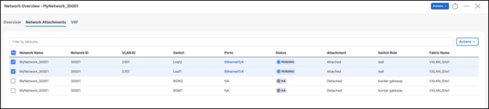
Step 2 - Attach the Network
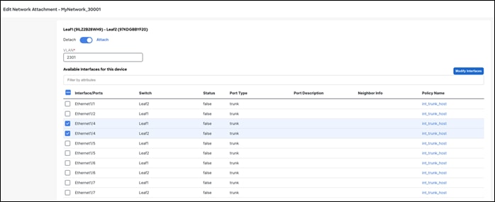
After saving the attachment, the Status field goes to the Pending state awaiting user preview.
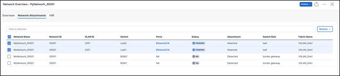
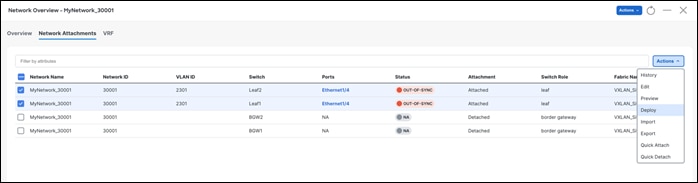
Step 3 - Preview and Deploy
NDFC generates a preview of the pending configuration. Upon approval, the changes can then be deployed.

The pending configurations on Leaf1 include the following:
◦ Creating a VRF and mapping it to an SVI
◦ Instantiating a BGP session for the VRF and advertising the L2VPN EVPN routes
◦ Creating an NVE interface for the network VNI
◦ Creating an SVI for the VLAN mapped to the network with the assigned gateway IP address
◦ Allowing the VLAN on the interfaces where the network is attached

Once approved you can deploy the configurations.
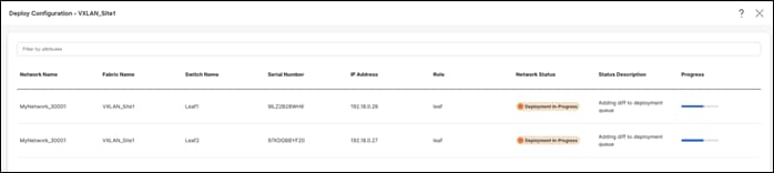
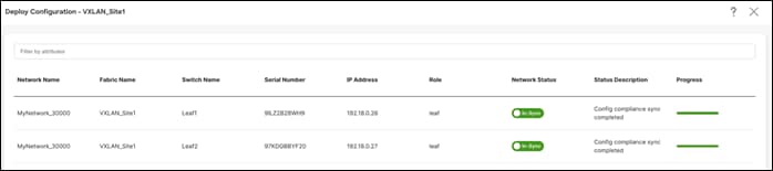
On successful deploy
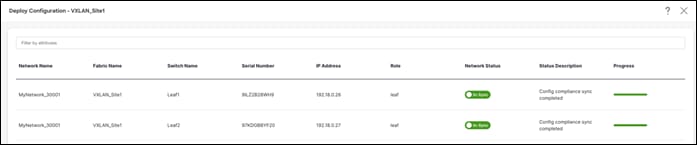
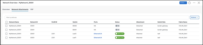
The Network Overview > Network Attachments page displays the attached interfaces.
A deployment history is available for all changes pushed from NDFC. For example, for the networks listed here, a deployment history as well as policy change history is available.
Deployment history –
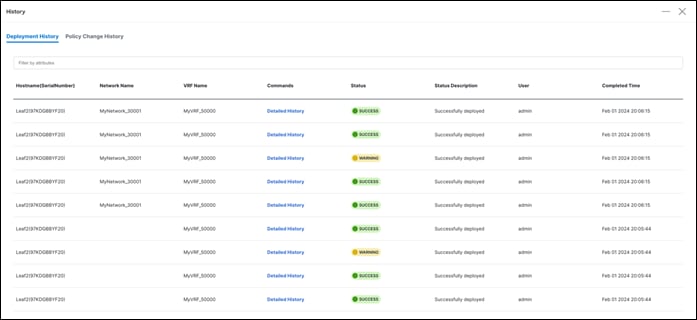
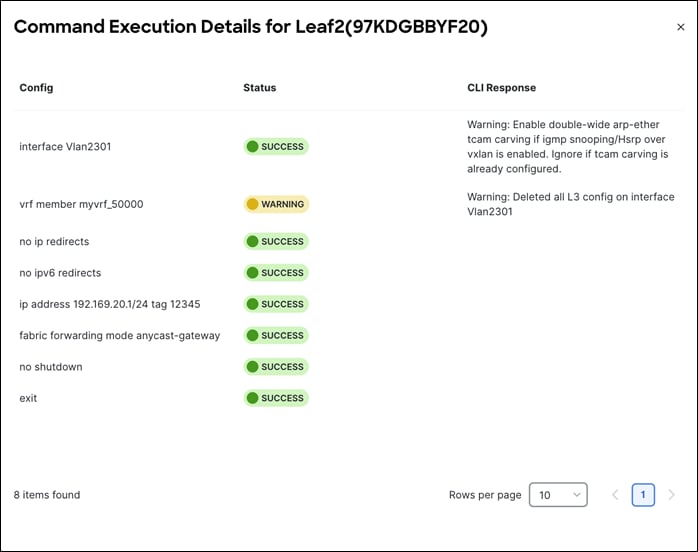
Click on Detailed History under the Commands column to view the status for the specified network. If a warning is generated by the switch, you see a WARNING status.
You can add the same network attachment to a group of interfaces as well.
NDFC also supports Quick Attach, which allows users to immediately add an attachment to the selected network or VRF. You can select multiple entries and attach them to a network/or VRF at the same time. To quickly attach any attachment to a network/VRF, choose Quick Attach from the Actions drop-down list.
You can enable VRF-Lite on the following devices:
• Border • Border Spine • Border Gateway • Border Gateway Spine • Border Super Spine
A Custom Network fabric is an important fabric type to consider in VRF Lite. Use a Custom Network fabric for devices that aren’t Nexus 3000 or Nexus 9000. Non-Nexus devices, specifically with an edge or a core role (prevalent in the VRF-Lite use cases) are placed in a custom network.
For more information, see VRF Lite.
Guidelines
◦ Depending on the NDFC release, auto inter-fabric connection (IFC) is supported on Cisco Nexus devices only or NX-OS and IOS XE/XR devices.
◦ Autoconfiguration is supported for the following cases:
◦ Border role in the VXLAN fabric and Edge Router role in the connected Custom Network fabric
◦ Border Gateway role in the VXLAN fabric and Edge Router role in the connected Custom Network fabric
◦ Border role to another Border role directly
◦ Autoconfiguration is not provided between two Border Gateways (BGWs). If VRF Lite is required between other roles, you must deploy it manually on the NDFC Web UI.
◦ You can configure ASR 1000 series routers and Catalyst 9000 series switches as edge routers. To configure, set up a VRF-Lite IFC, and connect it as a border device with a VXLAN fabric.
◦ You can configure ASR 9000 series routers as edge routers in managed mode.
◦ If the device in the Custom Network fabric is non-Nexus, you must create an IFC manually.
◦ Ensure that no user policy is enabled on the interface that connects to the edge router. If a policy exists, then the interface is not configured.
◦ To deploy configurations in the Custom Network fabric, you must uncheck the Fabric Monitor Mode check box in the Custom Network fabric settings. When a Custom Network is set to Fabric Monitor Mode only, you cannot deploy configurations on the switches.
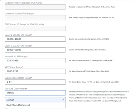
The following are the two modes in which you can deploy VRF Lite. By default, VRF Lite deployment is set to Manual. The settings can be changed based on user requirement.
◦ Manual - Use this option to deploy the VRF-Lite IFCs manually between the source and the destination devices.
◦ Back2Back&ToExternal - Use this option to automatically configure VRF-Lite IFCs between a border switch and the edge or core switches in a Custom Network fabric or between back-to-back border switches in a VXLAN EVPN fabric.
You can find the setting under the Resources tab under fabric settings.
Below are the use cases of VRF Lite:
◦ Automatic VRF Lite (IFC) Configuration (Auto IFC is supported on Cisco Nexus devices only)
◦ VRF Lite between Cisco Nexus 9000 based Border and Cisco Nexus 9000 based Edge Router
◦ VRF Lite between Cisco Nexus 9000 based Border and Non-Cisco device
◦ VRF Lite between Cisco Nexus 9000 based Border and Non-Nexus device
All of the above use cases are discussed in the VRF Lite Configuration Guide.
Apart from VRF Lite, seamless gateway protocols such as VXLAN EVPN to SR-MPLS and MPLS LDP L3VPN handoff is also supported for connecting a VXLAN fabric to an external Layer 3 domain.
For more information on this use case, see MPLS SR and LDP Handoff.
Day 2 refers to network operations, visibility, and monitoring aspects. NDFC provides a lot of visibility and operational features for NDFC fabrics.
All the below maintenance and operational features are supported for VXLAN fabrics.
● Image Management- Upgrades, Downgrades, EPLDs, RPMs, SMUs
● Change Management and Rollback
● Inventory View
● Event Analytics
● Deployment History, Audit Logs
● Backup & Restore
● Performance Metrics, Link and Interface stats, Protocol Views
● Programmable Reports
● Virtual infrastructure (VMM, K8s, OpenStack) Visibility
● Endpoint locator (EPL)
● VXLAN OAM
For more information on the above features, see the Cisco NDFC User Content Collection page and specify the release version and persona from the drop-down lists.
Note:
● To use alarms and get immediate notification of link/interfaces/switches down etc., set up an NDFC TRAP destination.
● For SYSLOGs, NDFC by default is not a SYSLOG receiver. You have to configure a SYSLOG receiver and define policies to capture SYSLOG messages of interest and trigger the appropriate alarms. Performance monitoring doesn’t require a SYSLOG receiver, as it is an SNMPv3 poll from NDFC to the switch.
● SCP is required for Image management, NX-API certificate installation, NDI functionality, and POAP.
● SNMP is also used for device discovery.
● Both SCP and SNMP pods are always enabled by default. Nexus Dashboard requires a minimum of two persistent IPs when enabling NDFC.
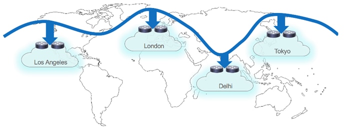
For high availability, networks are deployed across sites and then interconnected using a DCI technology such as VXLAN Multi-Site. The VXLAN Multi-Site architecture enables extending connectivity and policies across sites and allows IP mobility and active-active use cases across sites.
Before delving into VXLAN Multi-Site, you need to understand a few fabric-specific terms:
• Standalone fabric - A fabric that is not part of a VXLAN Multi-Site is referred to as a standalone fabric from the VXLAN Multi-Site perspective. Before the VXLAN Multi-Site concept, all fabrics were considered standalone, though two or more such fabrics can be connected with each other.
• Member fabrics - Fabrics that are part of a VXLAN Multi-Site are called member fabrics or members. Create a standalone fabric first and then move it within a VXLAN Multi-Site as a member fabric.
A VXLAN Multi-Site fabric is a multi-fabric container that is created to manage multiple Data Center VXLAN EVPN member fabrics. A VXLAN Multi-Site fabric is a single point of control for defining overlay networks and VRFs that are shared across member fabrics.
When fabrics that are designated as part of a multifabric overlay network domain are moved under the VXLAN Multi-Site fabric as a member fabric, the member fabrics share the networks and VRFs created at the VXLAN Multi-Site level. This way, you can consistently provision networks and VRFs for different fabrics, at one go. It significantly reduces the time and complexity involving multiple fabric provisioning. A Data Center VXLAN EVPN fabric or a VXLAN Multi-Site External Network fabric can be added as a member fabric in a VXLAN Multi-Site fabric. With NDFC Release 12.1.3, NDFC provides support for adding a Campus EVPN VXLAN fabric as a member fabric in a VXLAN Multi-Site fabric. As server networks and VRFs are shared across the member fabrics as one stretched network, provisioning new networks and VRFs is provided at the VXLAN Multi-Site fabric level. You can create new networks and VRFs only for a VXLAN Multi-Site fabric. All the member fabrics inherit any new network and VRF created for the VXLAN Multi-Site fabric. The topology view for the VXLAN Multi-Site fabric displays all member fabrics, and how they are connected to each other, in one view. You can deploy overlay networks and VRFs on member fabrics from a single topology deployment screen, instead of deploying each member fabric separately.
When a standalone fabric is added to a VXLAN Multi-Site fabric, the following actions take place:
● The standalone fabric’s relevant attributes, network and VRF definitions are evaluated with that of the VXLAN Multi-Site fabric. If there are no conflicts, then the standalone fabric becomes a member fabric of the VXLAN Multi-Site fabric. If there is a conflict, then adding a standalone fabric to the VXLAN Multi-Site fabric fails and the conflicts are logged in the pending error logs for the VXLAN Multi-Site fabric. You can resolve the conflicts and then add the standalone fabric to the VXLAN Multi-Site fabric again.
● All the VRFs and network definitions from the standalone fabric that do not have presence in the VXLAN Multi-Site fabric are copied over to the VXLAN Multi-Site fabric and in turn inherited to each of its other existing member fabrics.
● The VRFs and networks (and their definitions) from the VXLAN Multi-Site fabric (such as the VRF of the VXLAN Multi-Site fabric, and Layer 2 and Layer 3 VNI parameters that do not have presence in the standalone fabric) are inherited into the standalone fabric that just became a member.
For more information, see VXLAN EVPN Multi-Site.
Integration of VXLAN Fabrics with Services like Firewalls and Load Balancers
NDFC supports the ability to insert Layer 4-Layer 7 (L4-L7) service devices in a data center fabric, and enables selectively redirecting traffic to these L4-L7 service devices.
Service Nodes
A service node is a L4-L7 device attached to a switch managed by NDFC like a leaf, border leaf, border spine, border super spine, or a border gateway. NDFC manages the switches that are attached to a service node and the interfaces of these attached switches. NDFC configures switches that are attached to service nodes so that a service chaining configuration can be deployed on these switches to forward traffic to the service node.
You need to create a Custom Network fabric and specify that a service node resides in that fabric during service node creation. NDFC does not auto-detect or discover a service node. You also have to specify the service node name, type, and form factor. The name of the service node has to be unique within a fabric. Ensure that the interfaces that the service node is attached to are in trunk mode and do not belong to any interface group.
L4-L7 service in NDFC does not manage or provision service nodes, such as a firewall, a load balancer, or a Virtual Network Function. Configurations involving intra-tenant and inter-tenant firewall for Layer 3 networks a one-arm Virtual Network Function, and one-arm and two-arm load balancers are supported. A one-arm firewall deployment is supported with eBGP peering and static peering options. L4-L7 services support both IPv4 and IPv6 addresses. NDFC supports multiple vendor service node attachments. Typical service node types that are deployed in a data center are firewalls, load balancers, and other Layer-4 to Layer-7 products. Examples of a few supported firewall vendors are Cisco Systems, Palo Alto Networks, Fortinet, Check Point Software Technologies, and others. Examples of a few supported load balancer vendors are F5 Networks, Citrix Systems, A10 Networks, and others. NDFC supports Cisco as well as non-Cisco L4-L7 service nodes for this feature.
You can add a L4-L7 service node, create route peering between the L4-L7 service node and the L4-L7 service leaf switch, and then selectively redirect traffic to these L4-L7 service nodes.
For more information, see the service redirection video that demonstrates how to orchestrate a L4-L7 service appliance with a VXLAN fabric in an NDFC data center. This demo covers provisioning, defining of service policies, and monitoring of redirected flows.
For more details and configuration details, see Layer 4 to Layer 7 Services Configuration.
Migration from Classic LAN to VXLAN Networks
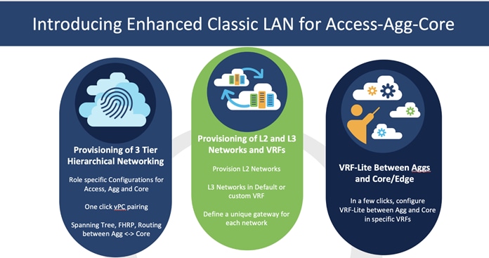
NDFC 12.1.3 introduced a new fabric template called the Enhanced Classic LAN fabric template. This template is introduced to completely automate the Layer 2 and Layer 3 aspects of Access – Aggregation – Core, as per Cisco best practice templates. This minimizes the learning curve and makes it easy to move to an SDN-driven approach, all while preparing for the future by improving scalability, creating the opportunity to build overlay network with VXLAN, and offering a wide variety of maintenance and operational features.

VXLAN as a technology has various benefits over traditional hierarchical classical Ethernet networks. Along with being the industry-standard, widely adopted, VXLAN provides the following:
● Proven and scalable
● Improves network performance
● Increases network reliability
● Simplifies network management and IP mobility
● Helps with segmentation and multi-tenancy
NDFC simplifies VXLAN greenfield (and brownfield) deployments in a few clicks, using the Data Center VXLAN EVPN fabric type while adhering to best practices as discussed extensively in this white paper. As you plan for VXLAN adoption, configure the Enhanced Classic LAN and VXLAN fabric types within the same NDFC instance, at least until you are ready to deprecate your Classic LAN network.
To migrate from an Enhanced Classic LAN to a VXLAN fabric type, consider the following topologies:
b2b vPC -> Back-to-Back vPC
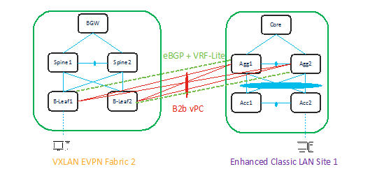
In both the topologies, make sure there is Layer 2 and Layer 3 connectivity between aggregations in the brownfield site and the Border Leaf/Border Gateway in the VXLAN site.
You must provision Layer 2 connectivity between vPC, port channels, and Layer 3 with VRF Life using NDFC policies. The following sections describe how to use NDFC to achieve this.
With NDFC 12.1.3, you can include an Enhanced Classic LAN (ECL) fabric as part of a VXLAN EVPN Multi-Site fabric along with a VXLAN fabric. This allows for VXLAN EVPN Multi-Site for DCI between an Enhanced Classic LAN and a VXLAN fabric. This helps with co-existence and future migration to VXLAN.
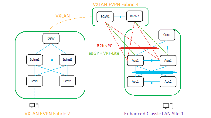
A topology for DCI is described below.
You can use a Data Center VXLAN EVPN fabric type for a greenfield VXLAN fabric consisting of a Leaf-Spine-Border Gateway (Fabric2) as well as for Border Gateways (BGWs) (Fabric3) to connect the aggregation switches. The Enhanced Classic LAN Site1 is the existing brownfield Classic LAN legacy site. Border Gateways allow you to create a VXLAN EVPN Multi-Site domain.
Adding all three fabrics in a VXLAN EVPN Multi-Site domain allows you to create Layer 2 and Layer 3 extensions of your networks and VRFs between the following:
● Border Gateways in Fabric3 and aggregations in Enhanced Classic LAN Site1
● Border Gateways in Fabric3 and Border Gateways in a greenfield VXLAN fabric Fabric1
You can use NDFC for the following:
● Importing and discovering existing brownfield classic Ethernet networks using an Enhanced Classic LAN fabric
● Setting up a greenfield VXLAN BGP EVPN fabric using POAP/Bootstrap/Switch IP discovery with BGWs
● VXLAN EVPN Multi-Site for Layer 2 and Layer 3 extension of networks between Classic and VXLAN fabrics
An Enhanced Classic LAN fabric uses a centralized gateway concept with First Hop Redundancy Protocol (FHRP). Whereas VXLAN uses a Distributed Anycast Gateway (DAG) concept. For co-existence of these two disparate kind of gateways keep both running at the same time. NX-OS introduced a new feature starting 10.2(3) as described here. As long as the switches are running NX-OS 10.2(3) or later, both DAG and FHRP gateways can co-exist, and you can use NDFC to provision the same. For NX-OS 10.2(3) and prior versions, only one kind of gateway can exist. Hence, you need to bring down the gateway for workloads from a brownfield Enhanced Classic LAN network and move it to the greenfield VXLAN fabric with an Anycast Gateway. Both options are discussed in the next section.
The white paper below provides all the details from connectivity to migration, co-existence, the required configurations, and how you can use NDFC to migrate from classic Ethernet environments to VXLAN BGP EVPN.
A detailed white paper on the Enhanced Classic LAN fabric is also available at:
https://www.cisco.com/c/en/us/td/docs/dcn/whitepapers/enhanced-classic-lan-in-cisco-ndfc-1213.html
This white paper covers the Day 0-Day 1-Day 2 aspects of a VXLAN EVPN Data Center fabric using NDFC.
Day 0 refers to the creation of a fabric with the desired settings, onboarding the switches in the fabric either using seed IP or using PowerOn Auto Provisioning (POAP). – Both greenfield and brownfield imports are supported. NDFC defines intent based on the role of the switches, vPC pairing, and interface management. This allows NDFC to manage your switches and fabrics.
At the end of Day 0 provisioning, NDFC creates a fully functional underlay for VXLAN EVPN technology.
Day 1 refers to the definition and attachment of overlays, networks and VRFs. This allows traffic to be encapsulated and sent between endpoints attached to the fabrics as part of the Day 0 bring up.
Day 2 refers to network operations, visibility, and monitoring. NDFC provides a lot of visibility and operational features for fabrics.
NDFC simplifies the provisioning of a single or multiple VXLAN fabrics, along with full support for VXLAN EVPN Multi-Site, all using Cisco best practice configurations. Both greenfield and brownfield deployments are supported. For more details, refer to the NDFC YouTube videos at: