
New and Changed Information
The following table provides an overview of the significant changes up to this current release. The table does not provide an exhaustive list of all changes or of the new features up to this release.
| Release Version | Feature | Description |
|---|---|---|
|
NDFC release 12.2.1 |
Support for Layer 3 VNI without VLAN feature |
Beginning with NDFC release 12.2.1, support is available for configuring a Layer 3 VNI without a VLAN per VRF when creating or editing the following fabric types:
A new field is available when creating or editing these fabric types to enable this feature. For more information, see Layer 3 VNI Without VLAN. |
|
NDFC release 12.2.1 |
Support for AI/ML QOS and queuing policies |
Beginning with NDFC release 12.2.1, support is available for configuring artificial intelligence (AI) and machine learning (ML) QoS and queuing policies when creating or editing the following fabric types:
A new field is available when creating or editing these fabric types to enable this feature. For more information, see AI/ML QoS Classification and Queuing Policies. |
VXLAN EVPN Fabrics Provisioning
Cisco Nexus Dashboard Fabric Controller provides an enhanced "Easy" fabric workflow for unified underlay and overlay provisioning of the VXLAN BGP EVPN configuration on Nexus 9000 and 3000 series of switches. The configuration of the fabric is achieved via a powerful, flexible, and customizable template-based framework. Using minimal user inputs, an entire fabric can be brought up with Cisco-recommended best practice configurations in a short period of time. The set of parameters exposed in the Fabric Settings allow you to tailor the fabric to your preferred underlay provisioning options.
Border devices in a fabric typically provide external connectivity via peering with appropriate edge/core/WAN routers. These edge/core routers may either be managed or monitored by Nexus Dashboard Fabric Controller. These devices are placed in a special fabric called the External Fabric. The same Nexus Dashboard Fabric Controller can manage multiple VXLAN BGP EVPN fabrics while also offering easy provisioning and management of Layer-2 and Layer-3 DCI underlay and overlay configuration among these fabrics using a special construct called a Multi-Site Domain (MSD) fabric.
The Nexus Dashboard Fabric Controller GUI functions for creating and deploying VXLAN BGP EVPN fabrics are as follows:
Manage > Fabrics > Create Fabric under Actions drop-down list.
Create, edit, and delete a fabric:
-
Create new VXLAN, MSD, and external VXLAN fabrics.
-
View the VXLAN and MSD fabric topologies, including connections between fabrics.
-
Update fabric settings.
-
Save and deploy updated changes.
-
Delete a fabric (if devices are removed).
Device discovery and provisioning start-up configurations on new switches:
-
Add switch instances to the fabric.
-
Provision start-up configurations and an IP address to a new switch through POAP configuration.
-
Update switch policies, save, and deploy updated changes.
-
Create intra-fabric and inter-fabric links (also called Inter-Fabric Connections [IFCs]).
Manage > Inventory > Interfaces > Create New Interface under Actions drop-down list.
Underlay provisioning:
-
Create, deploy, view, edit, and delete a port-channel, vPC switch pair, Straight Through FEX (ST-FEX), Active-Active FEX (AA-FEX), loopback, subinterface, etc.
-
Create breakout and unbreakout ports.
-
Shut down and bring up interfaces.
-
Rediscover ports and view interface configuration history.
Manage > Inventory > Switches > Add Switches under Actions drop-down list.
Overlay network provisioning.
-
Create new overlay networks and VRFs (from the range specified in fabric creation).
-
Provision the overlay networks and VRFs on the switches of the fabric.
-
Undeploy the networks and VRFs from the switches.
-
Remove the provisioning from the fabric in Nexus Dashboard Fabric Controller.
Manage > Inventory > Switches > Switch Overview > Services menu option.
Provisioning of configuration on service leafs to which L4-7 service appliances may be attached. For more information, see L4-L7 Service Basic Workflow.
This chapter mostly covers configuration provisioning for a single VXLAN BGP EVPN fabric. EVPN Multi-Site provisioning for Layer-2/Layer-3 DCI across multiple fabrics using the MSD fabric, is documented in a separate chapter. The deployment details of how overlay Networks and VRFs can be easily provisioned from the Fabric Controller is covered in the "Networks" and "VRFs" sections in About Fabric Overview for LAN Operational Mode Setups.
Guidelines for VXLAN BGP EVPN Fabrics Provisioning
-
For any switch to be successfully imported into Nexus Dashboard Fabric Controller, the user specified for discovery/import, should have the following permissions:
-
SSH access to the switch
-
Ability to perform SNMPv3 queries
-
Ability to run the show commands including show run, show interfaces, etc.
-
Ability to execute the guestshell commands, which are prefixed by run guestshell for the Nexus Dashboard Fabric Controller tracker.
-
-
The switch discovery user need not have the ability to make any configuration changes on the switches. It is primarily used for read access.
-
When an invalid command is deployed by Nexus Dashboard Fabric Controller to a device, for example, a command with an invalid key chain due to an invalid entry in the fabric settings, an error is generated displaying this issue. This error is not cleared after correcting the invalid fabric entry. You need to manually clean up or delete the invalid commands to clear the error.
Note that the fabric errors related to the command execution are automatically cleared only when the same failed command succeeds in the subsequent deployment.
-
LAN credentials are required to be set of any user that needs to be perform any write access to the device. LAN credentials need to be set on the Nexus Dashboard Fabric Controller, on a per user per device basis. When a user imports a device into the Easy Fabric, and LAN credentials are not set for that device, Nexus Dashboard Fabric Controller moves this device to a migration mode. Once the user sets the appropriate LAN credentials for that device, a subsequent Save & Deploy retriggers the device import process.
-
The Save & Deploy button triggers the intent regeneration for the entire fabric as well as a configuration compliance check for all the switches within the fabric. This button is required but not limited to the following cases:
-
A switch or a link is added, or any change in the topology
-
A change in the fabric settings that must be shared across the fabric
-
A switch is removed or deleted
-
A new vPC pairing or unpairing is done
-
A change in the role for a device
When you click Recalculate Config, the changes in the fabric are evaluated, and the configuration for the entire fabric is generated. Click Preview Config to preview the generated configuration, and then deploy it at a fabric level. Therefore, Deploy Config can take more time depending on the size of the fabric.
+ When you right-click on a switch icon, you can use the Deploy config to switches option to deploy per switch configurations. This option is a local operation for a switch, that is, the expected configuration or intent for a switch is evaluated against it’s current running configuration, and a config compliance check is performed for the switch to get the In-Sync or Out-of-Sync status. If the switch is out of sync, the user is provided with a preview of all the configurations running in that particular switch that vary from the intent defined by the user for that respective switch.
-
-
Persistent configuration diff is seen for the command line: system nve infra-vlanintforce. The persistent diff occurs if you have deployed this command via the freeform configuration to the switch. Although the switch requires the force keyword during deployment, the running configuration that is obtained from the switch in Nexus Dashboard Fabric Controller doesn’t display the force keyword. Therefore, the system nve infra-vlanintforce command always shows up as a diff.
The intent in Nexus Dashboard Fabric Controller contains the line:
system nve infra-vlan int force
The running config contains the line:
system nve infra-vlan [int]
As a workaround to fix the persistent diff, edit the freeform config to remove the force keyword after the first deployment such that it is system nve infra-vlan int.
The force keyword is required for the initial deploy and must be removed after a successful deploy. You can confirm the diff by using the Side-by-side Comparison tab in the Config Preview window.
The persistent diff is also seen after a write erase and reload of a switch. Update the intent on Nexus Dashboard Fabric Controller to include the force keyword, and then you need to remove the force keyword after the first deployment.
-
When the switch contains the hardware access-list tcam region arp-ether 256 command, which is deprecated without the double-wide keyword, the below warning is displayed:

Configuring the arp-ether region without "double-wide" is deprecated and can result in silent non-vxlan packet drops. Use the "double-wide" keyword when carving TCAM space for the arp-ether region.
Since the original hardware access-list tcam region arp-ether 256 command doesn’t match the policies in Nexus Dashboard Fabric Controller, this config is captured in the switch_freeform policy. After the hardware access-list tcam region arp-ether 256 double-wide command is pushed to the switch, the original tcam command that does not contain the double-wide keyword is removed.
You must manually remove the hardware access-list tcam region arp-ether 256 command from the switch_freeform policy. Otherwise, config compliance shows a persistent diff.
Here is an example of the hardware access-list command on the switch:
switch(config)# show run | inc arp-ether
switch(config)# hardware access-list tcam region arp-ether 256
Warning: Please save config and reload the system for the configuration to take effect
switch(config)# show run | inc arp-ether
hardware access-list tcam region arp-ether 256
switch(config)#
switch(config)# hardware access-list tcam region arp-ether 256 double-wide
Warning: Please save config and reload the system for the configuration to take effect
switch(config)# show run | inc arp-ether
hardware access-list tcam region arp-ether 256 double-wide
You can see that the original tcam command is overwritten.
Creating a VXLAN EVPN Fabric Using the Data Center VXLAN EVPN Template
This topic describes how to create a new VXLAN EVPN fabric using the Data Center VXLAN EVPN template and contains descriptions for the IPv4 underlay.

You can create a Data Center VXLAN EVPN fabric with IPv6 only underlay. The IPv6 underlay is supported only for the Data Center VXLAN EVPN template. For information about the IPv6 underlay, see Configuring a VXLANv6 Fabric.
-
Navigate to the LAN Fabrics page:
Manage > Fabrics
-
Click Actions > Create Fabric.
The Create Fabric window appears.
-
Enter a unique name for the fabric in the Fabric Name field, then click Choose Fabric.
A list of all available fabric templates are listed.
-
From the available list of fabric templates, choose the Data Center VXLAN EVPN template, then click Select.
-
Enter the necessary field values to create a fabric.
The tabs and their fields in the screen are explained in the following sections. The overlay and underlay network parameters are included in these tabs.
If you’re creating a standalone fabric as a potential member fabric of an MSD fabric (used for provisioning overlay networks for fabrics that are connected through EVPN Multi-Site technology), see VXLAN EVPN Multi-Site before creating the member fabric.
-
When you have completed the necessary configurations, click Save.
-
Click on the fabric to display a summary in the slide-in pane.
-
Click on the Launch icon to display the Fabric Overview.
-
General Parameters
The General Parameters tab is displayed by default. The fields in this tab are described in the following table.
| Field | Description |
|---|---|
|
BGP ASN |
Enter the BGP AS number the fabric is associated with. This must be same as existing fabric. |
|
Enable IPv6 Underlay |
Enable the IPv6 underlay feature. For information, see the section "Configuring a VXLANv6 Fabric" in Data Center VXLAN EVPN_. |
|
Enable IPv6 Link-Local Address |
Enables the IPv6 Link-Local address. |
|
Fabric Interface Numbering |
Specifies whether you want to use point-to-point (p2p) or unnumbered networks. |
|
Underlay Subnet IP Mask |
Specifies the subnet mask for the fabric interface IP addresses. |
|
Underlay Subnet IPv6 Mask |
Specifies the subnet mask for the fabric interface IPv6 addresses. |
|
Underlay Routing Protocol |
The IGP used in the fabric, OSPF, or IS-IS. |
|
Route-Reflectors (RRs) |
The number of spine switches that are used as route reflectors for transporting BGP traffic. Choose 2 or 4 from the drop-down box. The default value is 2. To deploy spine devices as RRs, Nexus Dashboard Fabric Controller sorts the spine devices based on their serial numbers, and designates two or four spine devices as RRs. If you add more spine devices, existing RR configuration won’t change. Increasing the count - You can increase the route reflectors from two to four at any point in time. Configurations are automatically generated on the other two spine devices designated as RRs. Decreasing the count - When you reduce four route reflectors to two, remove the unneeded route reflector devices from the fabric. Follow these steps to reduce the count from 4 to 2.
You can preselect RRs and RPs before performing the first Save & Deploy operation. For more information, see Preselecting Switches as Route-Reflectors and Rendezvous-Points. |
|
Anycast Gateway MAC |
Specifies the anycast gateway MAC address. |
|
Enable Performance Monitoring |
Check the check box to enable performance monitoring. Ensure that you do not clear interface counters from the Command Line Interface of the switches. Clearing interface counters can cause the Performance Monitor to display incorrect data for traffic utilization. If you must clear the counters and the switch has both |
What’s next: Complete the configurations in another tab if necessary, or click Save when you have completed the necessary configurations for this fabric.
Replication
The fields in the Replication tab are described in the following table. Most of the fields are automatically generated based on Cisco-recommended best practice configurations, but you can update the fields if needed.
| Field | Description |
|---|---|
|
Replication Mode |
The mode of replication that is used in the fabric for BUM (Broadcast, Unknown Unicast, Multicast) traffic. The choices are Ingress Replication or Multicast. When you choose Ingress replication, the multicast related fields get disabled. You can change the fabric setting from one mode to the other, if no overlay profile exists for the fabric. |
|
Multicast Group Subnet |
IP address prefix used for multicast communication. A unique IP address is allocated from this group for each overlay network. The replication mode change isn’t allowed if a policy template instance is created for the current mode. For example, if a multicast related policy is created and deployed, you can’t change the mode to Ingress. |
|
Enable Tenant Routed Multicast (TRM) |
Check the check box to enable Tenant Routed Multicast (TRM) that allows overlay multicast traffic to be supported over EVPN/MVPN in the VXLAN BGP EVPN fabric. |
|
Default MDT Address for TRM VRFs |
The multicast address for Tenant Routed Multicast traffic is populated. By default, this address is from the IP prefix specified in the Multicast Group Subnet field. When you update either field, ensure that the TRM address is chosen from the IP prefix specified in Multicast Group Subnet. For more information, see the section "Overview of Tenant Routed Multicast" in Configuring Tenant Routed Multicast. |
|
Rendezvous-Points |
Enter the number of spine switches acting as rendezvous points. |
|
RP mode |
Choose from the two supported multicast modes of replication, ASM (for Any-Source Multicast [ASM]) or BiDir (for Bidirectional PIM [BIDIR-PIM]). When you choose ASM, the BiDir related fields aren’t enabled. When you choose BiDir, the BiDir related fields are enabled.
BIDIR-PIM is supported on Cisco’s Cloud Scale Family platforms 9300-EX and 9300-FX/FX2, and software release 9.2(1) onwards. When you create a new VRF for the fabric overlay, this address is populated in the Underlay Multicast Address field, in the Advanced tab. |
|
Underlay RP Loopback ID |
The loopback ID used for the rendezvous point (RP), for multicast protocol peering purposes in the fabric underlay. |
|
Underlay Primary RP Loopback ID |
Enabled if you choose BIDIR-PIM as the multicast mode of replication. The primary loopback ID used for the phantom RP, for multicast protocol peering purposes in the fabric underlay. |
|
Underlay Backup RP Loopback ID |
Enabled if you choose BIDIR-PIM as the multicast mode of replication. The secondary loopback ID used for the phantom RP, for multicast protocol peering purposes in the fabric underlay. |
|
Underlay Second Backup RP Loopback Id |
Used for the second fallback Bidir-PIM Phantom RP. |
|
Underlay Third Backup RP Loopback Id |
Used for the third fallback Bidir-PIM Phantom RP. |
What’s next: Complete the configurations in another tab if necessary, or click Save when you have completed the necessary configurations for this fabric.
VPC
The fields in the VPC tab are described in the following table. Most of the fields are automatically generated based on Cisco-recommended best practice configurations, but you can update the fields if needed.
| Field | Description |
|---|---|
|
vPC Peer Link VLAN |
VLAN used for the vPC peer link SVI. |
|
Make vPC Peer Link VLAN as Native VLAN |
Enables vPC peer link VLAN as Native VLAN. |
|
vPC Peer Keep Alive option |
Choose the management or loopback option. If you want to use IP addresses assigned to the management port and the management VRF, choose management. If you use IP addresses assigned to loopback interfaces (and a non-management VRF), choose loopback. If you use IPv6 addresses, you must use loopback IDs. |
|
vPC Auto Recovery Time |
Specifies the vPC auto recovery time-out period in seconds. |
|
vPC Delay Restore Time |
Specifies the vPC delay restore period in seconds. |
|
vPC Peer Link Port Channel ID |
Specifies the Port Channel ID for a vPC Peer Link. By default, the value in this field is 500. |
|
vPC IPv6 ND Synchronize |
Enables IPv6 Neighbor Discovery synchronization between vPC switches. The check box is enabled by default. Uncheck the check box to disable the function. |
|
vPC advertise-pip |
Select the check box to enable the Advertise PIP feature. You can enable the advertise PIP feature on a specific vPC as well. . |
|
Enable the same vPC Domain Id for all vPC Pairs |
Enable the same vPC Domain ID for all vPC pairs. When you select this field, the vPC Domain Id field is editable. |
|
vPC Domain Id |
Specifies the vPC domain ID to be used on all vPC pairs. |
|
vPC Domain Id Range |
Specifies the vPC Domain Id range to use for new pairings. |
|
Enable QoS for Fabric vPC-Peering |
Enable QoS on spines for guaranteed delivery of vPC Fabric Peering communication.
QoS for vPC fabric peering and queuing policies options in fabric settings are mutually exclusive. |
|
QoS Policy Name |
Specifies QoS policy name that should be same on all fabric vPC peering spines. The default name is spine_qos_for_fabric_vpc_peering. |
What’s next: Complete the configurations in another tab if necessary, or click Save when you have completed the necessary configurations for this fabric.
Protocols
The fields in the Protocols tab are described in the following table. Most of the fields are automatically generated based on Cisco-recommended best practice configurations, but you can update the fields if needed.
| Field | Description |
|---|---|
|
Underlay Routing Loopback Id |
The loopback interface ID is populated as 0 since loopback0 is usually used for fabric underlay IGP peering purposes. |
|
Underlay VTEP Loopback Id |
The loopback interface ID is populated as 1 since loopback1 is used for the VTEP peering purposes. |
|
Underlay Anycast Loopback Id |
The loopback interface ID is greyed out and used for vPC Peering in VXLANv6 Fabrics only. |
|
Underlay Routing Protocol Tag |
The tag defining the type of network. |
|
OSPF Area ID |
The OSPF area ID, if OSPF is used as the IGP within the fabric.
The OSPF or IS-IS authentication fields are enabled based on your selection in the Underlay Routing Protocol field in the General tab. |
|
Enable OSPF Authentication |
Select the check box to enable OSPF authentication. Deselect the check box to disable it. If you enable this field, the OSPF Authentication Key ID and OSPF Authentication Key fields get enabled. |
|
OSPF Authentication Key ID |
The Key ID is populated. |
|
OSPF Authentication Key |
The OSPF authentication key must be the 3DES key from the switch.
Plain text passwords are not supported. Log in to the switch, retrieve the encrypted key and enter it in this field. Refer, Retrieving the Authentication Key section for details. |
|
IS-IS Level |
Select the IS-IS level from this drop-down list. |
|
Enable IS-IS Network Point-to-Point |
Enables network point-to-point on fabric interfaces which are numbered. |
|
Enable IS-IS Authentication |
Select the check box to enable IS-IS authentication. Deselect the check box to disable it. If you enable this field, the IS-IS authentication fields are enabled. |
|
IS-IS Authentication Keychain Name |
Enter the Keychain name, such as CiscoisisAuth. |
|
IS-IS Authentication Key ID |
The Key ID is populated. |
|
IS-IS Authentication Key |
Enter the Cisco Type 7 encrypted key.
Plain text passwords are not supported. Log in to the switch, retrieve the encrypted key and enter it in this field. Refer the Retrieving the Authentication Key section for details. |
|
Set IS-IS Overload Bit |
When enabled, set the overload bit for an elapsed time after a reload. |
|
IS-IS Overload Bit Elapsed Time |
Allows you to clear the overload bit after an elapsed time in seconds. |
|
Enable BGP Authentication |
Select the check box to enable BGP authentication. Deselect the check box to disable it. If you enable this field, the BGP Authentication Key Encryption Type and BGP Authentication Key fields are enabled.
If you enable BGP authentication using this field, leave the iBGP Peer-Template Config field blank to avoid duplicate configuration. |
|
BGP Authentication Key Encryption Type |
Choose the 3 for 3DES encryption type, or 7 for Cisco encryption type. |
|
BGP Authentication Key |
Enter the encrypted key based on the encryption type.
Plain text passwords are not supported. Log in to the switch, retrieve the encrypted key and enter it in the BGP Authentication Key field. Refer the Retrieving the Authentication Key section for details. |
|
Enable PIM Hello Authentication |
Select this check box to enable PIM hello authentication on all the intra-fabric interfaces of the switches in a fabric. This check box is editable only for the Multicast replication mode. Note this check box is valid only for the IPv4 underlay. |
|
PIM Hello Authentication Key |
Specifies the PIM hello authentication key. For more information, see Retrieving PIM Hello Authentication Key. To retrieve the PIM Hello Authentication Key, perform the following steps:
|
|
Enable BFD |
Check the check box to enable feature bfd on all switches in the fabric. This feature is valid only on IPv4 underlay and the scope is within a fabric. BFD within a fabric is supported natively. The BFD feature is disabled by default in the Fabric Settings. If enabled, BFD is enabled for the underlay protocols with the default settings. Any custom required BFD configurations must be deployed via the per switch freeform or per interface freeform policies. The following config is pushed after you select the Enable BFD check box: For information about BFD feature compatibility, refer your respective platform documentation and for information about the supported software images, see Compatibility Matrix for Cisco. |
|
Enable BFD for iBGP |
Check the check box to enable BFD for the iBGP neighbor. This option is disabled by default. |
|
Enable BFD for OSPF |
Check the check box to enable BFD for the OSPF underlay instance. This option is disabled by default, and it is grayed out if the link state protocol is ISIS. |
|
Enable BFD for ISIS |
Check the check box to enable BFD for the ISIS underlay instance. This option is disabled by default, and it is grayed out if the link state protocol is OSPF. |
|
Enable BFD for PIM |
Check the check box to enable BFD for PIM. This option is disabled by default, and it is be grayed out if the replication mode is Ingress.Following are examples of the BFD global policies: |
|
Enable BFD Authentication |
Check the check box to enable BFD authentication. If you enable this field, the BFD Authentication Key ID and BFD Authentication Key fields are editable.
BFD Authentication is not supported when the Fabric Interface Numbering field under the General tab is set to unnumbered. The BFD authentication fields will be grayed out automatically. BFD authentication is valid for only for P2P interfaces. |
|
BFD Authentication Key ID |
Specifies the BFD authentication key ID for the interface authentication. The default value is 100. |
|
BFD Authentication Key |
Specifies the BFD authentication key. For information about how to retrieve the BFD authentication parameters. |
|
iBGP Peer-Template Config |
Add iBGP peer template configurations on the leaf switches to establish an iBGP session between the leaf switch and route reflector. If you use BGP templates, add the authentication configuration within the template and uncheck the Enable BGP Authentication check box to avoid duplicate configuration. In the sample configuration, the 3DES password is displayed after password 3. The following fields can be used to specify different configurations:
In a brownfield migration, if the spine and leaf use different peer template names, both iBGP Peer-Template Config and Leaf/Border/Border Gateway iBGP Peer-Template Config fields need to be set according to the switch config. If spine and leaf use the same peer template name and content (except for the "route-reflector-client" CLI), only iBGP Peer-Template Config field in fabric setting needs to be set. If the fabric settings on iBGP peer templates do not match the existing switch configuration, an error message is generated and the migration will not proceed. |
What’s next: Complete the configurations in another tab if necessary, or click Save when you have completed the necessary configurations for this fabric.
Advanced
The fields in the Advanced tab are described in the following table. Most of the fields are automatically generated based on Cisco-recommended best practice configurations, but you can update the fields if needed.
| Field | Description |
|---|---|
|
VRF Template |
Specifies the VRF template for creating VRFs. |
|
Network Template |
Specifies the network template for creating networks. |
|
VRF Extension Template |
Specifies the VRF extension template for enabling VRF extension to other fabrics. |
|
Network Extension Template |
Specifies the network extension template for extending networks to other fabrics. |
|
Overlay Mode |
VRF/Network configuration using config-profile or CLI, default is config-profile. For more information, see Overlay Mode. |
|
Enable L3VNI w/o VLAN |
Beginning with NDFC release 12.2.1, check the box to enable the Layer 3 VNI without VLAN feature. The setting at this fabric-level field affects the related field at the VRF level. For more information, see:
|
|
Site ID |
The ID for this fabric if you are moving this fabric within an MSD. The site ID is mandatory for a member fabric to be a part of an MSD. Each member fabric of an MSD has a unique site ID for identification. |
|
Intra Fabric Interface MTU |
Specifies the MTU for the intra fabric interface. This value should be an even number. |
|
Layer 2 Host Interface MTU |
Specifies the MTU for the layer 2 host interface. This value should be an even number. |
|
Unshut Host Interfaces by Default |
Check this check box to unshut the host interfaces by default. |
|
Power Supply Mode |
Choose the appropriate power supply mode. |
|
CoPP Profile |
Choose the appropriate Control Plane Policing (CoPP) profile policy for the fabric. By default, the strict option is populated. |
|
VTEP HoldDown Time |
Specifies the NVE source interface hold down time. |
|
Brownfield Overlay Network Name Format |
Enter the format to be used to build the overlay network name during a brownfield import or migration. The network name should not contain any white spaces or special characters except underscore () and hyphen (-). The network name must not be changed once the brownfield migration has been initiated. See the _Creating Networks for the Standalone Fabric section for the naming convention of the network name. The syntax is [<string> | $$VLAN_ID$$] $$VNI$$ [<string>| $$VLAN_ID$$] and the default value is Auto_Net_VNI$$VNI$$_VLAN$$VLAN_ID$$. When you create networks, the name is generated according to the syntax you specify. The following list describes the variables in the syntax:
An example overlay network name: Site_VNI12345_VLAN1234
Ignore this field for greenfield deployments. The Brownfield Overlay Network Name Format applies for the following brownfield imports:
|
|
Enable CDP for Bootstrapped Switch |
Enables CDP on management (mgmt0) interface for bootstrapped switch. By default, for bootstrapped switches, CDP is disabled on the mgmt0 interface. |
|
Enable VXLAN OAM |
Enables the VXLAM OAM functionality for devices in the fabric. This is enabled by default. Uncheck the check box to disable VXLAN OAM function. If you want to enable the VXLAN OAM function on specific switches and disable on other switches in the fabric, you can use freeform configurations to enable OAM and disable OAM in the fabric settings.
The VXLAN OAM feature in Cisco Nexus Dashboard Fabric Controller is only supported on a single fabric or site. |
|
Enable Tenant DHCP |
Check the check box to enable feature dhcp and associated configurations globally on all switches in the fabric. This is a pre-requisite for support of DHCP for overlay networks that are part of the tenant VRFs.
Ensure that Enable Tenant DHCP is enabled before enabling DHCP-related parameters in the overlay profiles. |
|
Enable NX-API |
Specifies enabling of NX-API on HTTPS. This check box is checked by default. |
|
Enable NX-API on HTTP Port |
Specifies enabling of NX-API on HTTP. Enable this check box and the Enable NX-API check box to use HTTP. This check box is checked by default. If you uncheck this check box, the applications that use NX-API and supported by Cisco Nexus Dashboard Fabric Controller, such as Endpoint Locator (EPL), Layer 4-Layer 7 services (L4-L7 services), VXLAN OAM, and so on, start using the HTTPS instead of HTTP.
If you check the Enable NX-API check box and the Enable NX-API on HTTP check box, applications use HTTP. |
|
Enable Policy-Based Routing (PBR) |
Check this check box to enable routing of packets based on the specified policy. Starting with Cisco NX-OS Release 7.0(3)I7(1) and later releases, this feature works on Cisco Nexus 9000 Series switches with Nexus 9000 Cloud Scale (Tahoe) ASICs. This feature is used along with the Layer 4-Layer 7 service workflow. For information on Layer 4-Layer 7 service, refer the Layer 4-Layer 7 Service chapter. |
|
Enable Strict Config Compliance |
Enable the Strict Config Compliance feature by selecting this check box. It enables bi-directional compliance checks to flag additional configs in the running config that are not in the intent/expected config. By default, this feature is disabled. |
|
Enable AAA IP Authorization |
Enables AAA IP authorization, when IP Authorization is enabled in the remote authentication server. This is required to support Nexus Dashboard Fabric Controller in scenarios where customers have strict control of which IP addresses can have access to the switches. |
|
Enable NDFC as Trap Host |
Select this check box to enable Nexus Dashboard Fabric Controller as an SNMP trap destination. Typically, for a native HA Nexus Dashboard Fabric Controller deployment, the eth1 VIP IP address will be configured as SNMP trap destination on the switches. By default, this check box is enabled. |
|
Anycast Border Gateway advertise-pip |
Enables to advertise Anycast Border Gateway PIP as VTEP. Effective on MSD fabric 'Recalculate Config'. |
|
Greenfield Cleanup Option |
Enable the switch cleanup option for switches imported into Nexus Dashboard Fabric Controller with Preserve-Config=No, without a switch reload. This option is typically recommended only for the fabric environments with Cisco Nexus 9000v Switches to improve on the switch clean up time. The recommended option for Greenfield deployment is to employ Bootstrap or switch cleanup with a reboot. In other words, this option should be unchecked. |
|
Enable Precision Time Protocol (PTP) |
Enables PTP across a fabric. When you check this check box, PTP is enabled globally and on core-facing interfaces. Additionally, the PTP Source Loopback Id and PTP Domain Id fields are editable. For more information, see the section "Precision Time Protocol for Data Center VXLAN EVPN Fabrics" in Precision Time Protocol for Data Center VXLAN EVPN Fabrics. |
|
PTP Source Loopback Id |
Specifies the loopback interface ID Loopback that is used as the Source IP Address for all PTP packets. The valid values range from 0 to 1023. The PTP loopback ID cannot be the same as RP, Phantom RP, NVE, or MPLS loopback ID. Otherwise, an error will be generated. The PTP loopback ID can be the same as BGP loopback or user-defined loopback which is created from Nexus Dashboard Fabric Controller. If the PTP loopback ID is not found during Deploy Config, the following error is generated: Loopback interface to use for PTP source IP is not found. Create PTP loopback interface on all the devices to enable PTP feature. |
|
PTP Domain Id |
Specifies the PTP domain ID on a single network. The valid values range from 0 to 127. |
|
Enable MPLS Handoff |
Check the check box to enable the MPLS Handoff feature. For more information, see MPLS SR and LDP Handoff. |
|
Underlay MPLS Loopback Id |
Specifies the underlay MPLS loopback ID. The default value is 101. |
|
Enable TCAM Allocation |
TCAM commands are automatically generated for VXLAN and vPC Fabric Peering when enabled. |
|
Enable Default Queuing Policies |
Check this check box to apply QoS policies on all the switches in this fabric. To remove the QoS policies that you applied on all the switches, uncheck this check box, update all the configurations to remove the references to the policies, and save and deploy. Pre-defined QoS configurations are included that can be used for various Cisco Nexus 9000 Series Switches. When you check this check box, the appropriate QoS configurations are pushed to the switches in the fabric. The system queuing is updated when configurations are deployed to the switches. You can perform the interface marking with defined queuing policies, if required, by adding the required configuration to the per interface freeform block. Review the actual queuing policies by opening the policy file in the template editor. From Cisco Nexus Dashboard Fabric Controller Web UI, choose Manage > Templates. Search for the queuing policies by the policy file name, for example, queuing_policy_default_8q_cloudscale. Choose the file. From the Actions drop-down list, select Edit template content to edit the policy. See the Cisco Nexus 9000 Series NX-OS Quality of Service Configuration Guide for platform specific details. |
|
N9K Cloud Scale Platform Queuing Policy |
Choose the queuing policy from the drop-down list to be applied to all Cisco Nexus 9200 Series Switches and the Cisco Nexus 9000 Series Switches that ends with EX, FX, and FX2 in the fabric. The valid values are queuing_policy_default_4q_cloudscale and queuing_policy_default_8q_cloudscale. Use the queuing_policy_default_4q_cloudscale policy for FEXes. You can change from the queuing_policy_default_4q_cloudscale policy to the queuing_policy_default_8q_cloudscale policy only when FEXes are offline. |
|
N9K R-Series Platform Queuing Policy |
Choose the queuing policy from the drop-down list to be applied to all Cisco Nexus switches that ends with R in the fabric. The valid value is queuing_policy_default_r_series. |
|
Other N9K Platform Queuing Policy |
Choose the queuing policy from the drop-down list to be applied to all other switches in the fabric other than the switches mentioned in the above two options. The valid value is queuing_policy_default_other. |
|
Enable AI/ML QOS and Queuing Policies |
Beginning with NDFC release 12.2.1, check the box to enable AI/ML QoS and queuing policies in the BGP fabric. For more information, see AI/ML QoS Classification and Queuing Policies.
This option is not available if you also enabled either of the following options:
|
|
AI / ML QOS & Queuing Policy |
This field is available if you checked the Enable AI/ML QOS and Queuing Policies option above. Beginning with NDFC release 12.2.1, choose the queuing policy from the drop-down list based on the predominant fabric link speed for certain switches in the fabric. For more information, see AI/ML QoS Classification and Queuing Policies. Options are:
|
|
Enable MACsec |
Enables MACsec for the fabric. For more information, Enabling MACsec. Freeform CLIs - Fabric level freeform CLIs can be added while creating or editing a fabric. They are applicable to switches across the fabric. You must add the configurations as displayed in the running configuration, without indentation. Switch level freeform configurations should be added via the switch freeform on NDFC. For more information, see Enabling Freeform Configurations on Fabric Switches. |
|
Leaf Freeform Config |
Add CLIs that should be added to switches that have the Leaf,Border, and Border Gateway roles. |
|
Spine Freeform Config |
Add CLIs that should be added to switches with a Spine, Border Spine, Border Gateway Spine, and Super Spine roles. |
|
Intra-fabric Links Additional Config |
Add CLIs that should be added to the intra-fabric links. |
What’s next: Complete the configurations in another tab if necessary, or click Save when you have completed the necessary configurations for this fabric.
Resources
The fields in the Resources tab are described in the following table. Most of the fields are automatically generated based on Cisco-recommended best practice configurations, but you can update the fields if needed.
| Field | Description |
|---|---|
|
Manual Underlay IP Address Allocation |
Do not check this check box if you are transitioning your VXLAN fabric management to Nexus Dashboard Fabric Controller.
|
|
Underlay Routing Loopback IP Range |
Specifies loopback IP addresses for the protocol peering. |
|
Underlay VTEP Loopback IP Range |
Specifies loopback IP addresses for VTEPs. |
|
Underlay RP Loopback IP Range |
Specifies the anycast or phantom RP IP address range. |
|
Underlay Subnet IP Range |
IP addresses for underlay P2P routing traffic between interfaces. |
|
Underlay MPLS Loopback IP Range |
Specifies the underlay MPLS loopback IP address range. For eBGP between Border of Easy A and Easy B, Underlay routing loopback and Underlay MPLS loopback IP range must be a unique range. It should not overlap with IP ranges of the other fabrics, else VPNv4 peering will not come up. |
|
Underlay Routing Loopback IPv6 Range |
Specifies Loopback0 IPv6 Address Range |
|
Underlay VTEP Loopback IPv6 Range |
Specifies Loopback1 and Anycast Loopback IPv6 Address Range. |
|
Underlay Subnet IPv6 Range |
Specifies IPv6 Address range to assign Numbered and Peer Link SVI IPs. |
|
BGP Router ID Range for IPv6 Underlay |
Specifies BGP router ID range for IPv6 underlay. |
|
Layer 2 VXLAN VNI Range |
Specifies the overlay VXLAN VNI range for the fabric (min:1, max:16777214). |
|
Layer 3 VXLAN VNI Range |
Specifies the overlay VRF VNI range for the fabric (min:1, max:16777214). |
|
Network VLAN Range |
VLAN range for the per switch overlay network (min:2, max:4094). |
|
VRF VLAN Range |
VLAN range for the per switch overlay Layer 3 VRF (min:2, max:4094). |
|
Subinterface Dot1q Range |
Specifies the subinterface range when L3 sub interfaces are used. |
|
VRF Lite Deployment |
Specify the VRF Lite method for extending inter fabric connections. The VRF Lite Subnet IP Range field specifies resources reserved for IP address used for VRF Lite when VRF Lite IFCs are auto-created. If you select Back2Back&ToExternal, then VRF Lite IFCs are auto-created. |
|
Auto Deploy for Peer |
This check box is applicable for VRF Lite deployment. When you select this checkbox, auto-created VRF Lite IFCs will have the Auto Generate Configuration for Peer field in the VRF Lite tab set. To access VRF Lite IFC configuration, navigate to the Links tab, select the particular link, and then choose Actions > Edit. You can check or uncheck the check box when the VRF Lite Deployment field is not set to Manual. This configuration only affects the new auto-created IFCs and does not affect the existing IFCs. You can edit an auto-created IFC and check or uncheck the Auto Generate Configuration for Peer field. This setting takes priority always. |
|
Auto Deploy Default VRF |
When you select this check box, the Auto Generate Configuration on default VRF field is automatically enabled for auto-created VRF Lite IFCs. You can check or uncheck this check box when the VRF Lite Deployment field is not set to Manual. The Auto Generate Configuration on default VRF field when set, automatically configures the physical interface for the border device, and establishes an EBGP connection between the border device and the edge device or another border device in a different VXLAN EVPN fabric. |
|
Auto Deploy Default VRF for Peer |
When you select this check box, the Auto Generate Configuration for NX-OS Peer on default VRF field is automatically enabled for auto-created VRF Lite IFCs. You can check or uncheck this check box when the VRF Lite Deployment field is not set to Manual. The Auto Generate Configuration for NX-OS Peer on default VRF field when set, automatically configures the physical interface and the EBGP commands for the peer NX-OS switch.
To access the Auto Generate Configuration on default VRF and Auto Generate Configuration for NX-OS Peer on default VRF fields for an IFC link, navigate to the Links tab, select the particular link and choose Actions > Edit. |
|
Redistribute BGP Route-map Name |
Defines the route map for redistributing the BGP routes in default VRF. |
|
VRF Lite Subnet IP Range and VRF Lite Subnet Mask |
These fields are populated with the DCI subnet details. Update the fields, as needed. The values shown in your screen are automatically generated. If you want to update the IP address ranges, VXLAN Layer 2/Layer 3 network ID ranges or the VRF/Network VLAN ranges, ensure the following:
When you update a range of values, ensure that it does not overlap with other ranges. You should only update one range of values at a time. If you want to update more than one range of values, do it in separate instances. For example, if you want to update L2 and L3 ranges, you should do the following.
|
|
Service Network VLAN Range |
Specifies a VLAN range in the Service Network VLAN Range field. This is a per switch overlay service network VLAN range. The minimum allowed value is 2 and the maximum allowed value is 3967. |
|
Auto Allocation of Unique IP on VRF Extension over VRF Lite IFC |
Automatically allocates a unique IPv4 address with subnet for the source and the destination interfaces for VRF extensions over VRF Lite IFC. When enabled, the system auto populates a unique IP address for the source and the destination interfaces for each extension in the VRF attachment. When you disable the feature, the system auto populates the same IP address for the source and the destination interfaces for the VRF extensions and these IP addresses are allocated in resource manager with the VRFs attached. The resource manager ensures that they are not used for any other purpose on the same VRF. |
|
Per VRF Per VTEP Loopback Auto-Provisioning |
Auto provisions a loopback address in IPv4 format for a VTEP that the system uses for VRF attachment. This option is not enabled by default. When enabled, the system allocates an IPv4 address from the IP pool that you have assigned for the VTEP loopback interface. |
|
Per VRF Per VTEP IP Pool for Loopback |
A pool of IP addresses assigned to the loopback interfaces on VTEPs for each VRF. |
|
Route Map Sequence Number Range |
Specifies the route map sequence number range. The minimum allowed value is 1 and the maximum allowed value is 65534. |
What’s next: Complete the configurations in another tab if necessary, or click Save when you have completed the necessary configurations for this fabric.
Manageability
The fields in the Manageability tab are described in the following table. Most of the fields are automatically generated based on Cisco-recommended best practice configurations, but you can update the fields if needed.
| Field | Description |
|---|---|
|
Inband Management |
Enabling this allows the management of the switches over their front panel interfaces. The Underlay Routing Loopback interface is used for discovery. If enabled, switches cannot be added to the fabric over their out-of-band (OOB) mgmt0 interface. To manage easy fabrics through Inband management, ensure that you have chosen Data in NDFC Web UI, Admin > System Settings > Server Settings > Admin. Both inband management and out-of-band connectivity (mgmt0) are supported for this setting. For more information, see the section "Inband Management and Inband POAP in Easy Fabrics" in Configuring Inband Management, Inband POAP Management, and Secure POAP. |
|
DNS Server IPs |
Specifies the comma separated list of IP addresses (v4/v6) of the DNS servers. |
|
DNS Server VRFs |
Specifies one VRF for all DNS servers or a comma separated list of VRFs, one per DNS server. |
|
NTP Server IPs |
Specifies comma separated list of IP addresses (v4/v6) of the NTP server. |
|
NTP Server VRFs |
Specifies one VRF for all NTP servers or a comma separated list of VRFs, one per NTP server. |
|
Syslog Server IPs |
Specifies the comma separated list of IP addresses (v4/v6) IP address of the syslog servers, if used. |
|
Syslog Server Severity |
Specifies the comma separated list of syslog severity values, one per syslog server. The minimum value is 0 and the maximum value is 7. To specify a higher severity, enter a higher number. |
|
Syslog Server VRFs |
Specifies one VRF for all syslog servers or a comma separated list of VRFs, one per syslog server. |
|
AAA Freeform Config |
Specifies the AAA freeform configurations. If AAA configurations are specified in the fabric settings, switch_freeform PTI with source as UNDERLAY_AAA and description as AAA Configurations will be created. |
What’s next: Complete the configurations in another tab if necessary, or click Save when you have completed the necessary configurations for this fabric.
Bootstrap
The fields in the Bootstrap tab are described in the following table. Most of the fields are automatically generated based on Cisco-recommended best practice configurations, but you can update the fields if needed.
| Field | Description |
|---|---|
|
Enable Bootstrap |
Select this check box to enable the bootstrap feature. Bootstrap allows easy day-0 import and bring-up of new devices into an existing fabric. Bootstrap leverages the NX-OS POAP functionality. Starting from Cisco NDFC Release 12.1.1e, to add more switches and for POAP capability, chose check box for Enable Bootstrap and Enable Local DHCP Server. For more information, see the section "Inband Management and Inband POAP in Easy Fabrics" in Configuring Inband Management, Inband POAP Management, and Secure POAP. After you enable bootstrap, you can enable the DHCP server for automatic IP address assignment using one of the following methods:
|
|
Enable Local DHCP Server |
Select this check box to initiate enabling of automatic IP address assignment through the local DHCP server. When you select this check box, the DHCP Scope Start Address and DHCP Scope End Address fields become editable. If you do not select this check box, Nexus Dashboard Fabric Controller uses the remote or external DHCP server for automatic IP address assignment. |
|
DHCP Version |
Select DHCPv4 or DHCPv6 from this drop-down list. When you select DHCPv4, the Switch Mgmt IPv6 Subnet Prefix field is disabled. If you select DHCPv6, the Switch Mgmt IP Subnet Prefix is disabled.
Cisco Nexus 9000 and 3000 Series Switches support IPv6 POAP only when switches are either Layer-2 adjacent (eth1 or out-of-band subnet must be a /64) or they are L3 adjacent residing in some IPv6 /64 subnet. Subnet prefixes other than /64 are not supported. |
|
DHCP Scope Start Address and DHCP Scope End Address |
Specifies the first and last IP addresses of the IP address range to be used for the switch out of band POAP. |
|
Switch Mgmt Default Gateway |
Specifies the default gateway for the management VRF on the switch. |
|
Switch Mgmt IP Subnet Prefix |
Specifies the prefix for the Mgmt0 interface on the switch. The prefix should be between 8 and 30. DHCP scope and management default gateway IP address specification - If you specify the management default gateway IP address 10.0.1.1 and subnet mask 24, ensure that the DHCP scope is within the specified subnet, between 10.0.1.2 and 10.0.1.254. |
|
Switch Mgmt IPv6 Subnet Prefix |
Specifies the IPv6 prefix for the Mgmt0 interface on the switch. The prefix should be between 112 and 126. This field is editable if you enable IPv6 for DHCP. |
|
Enable AAA Config |
Select this check box to include AAA configurations from the Manageability tab as part of the device start-up config post bootstrap. |
|
DHCPv4/DHCPv6 Multi Subnet Scope |
Specifies the field to enter one subnet scope per line. This field is editable after you check the Enable Local DHCP Server check box. The format of the scope should be defined as: DHCP Scope Start Address, DHCP Scope End Address, Switch Management Default Gateway, Switch Management Subnet Prefix For example: 10.6.0.2, 10.6.0.9, 10.6.0.1, 24 |
|
Bootstrap Freeform Config |
(Optional) Enter additional commands as needed. For example, if you require some additional configurations to be pushed to the device and be available post device bootstrap, they can be captured in this field, to save the desired intent. After the devices boot up, they will contain the configuration defined in the Bootstrap Freeform Config field. Copy-paste the running-config to a freeform config field with correct indentation, as seen in the running configuration on the NX-OS switches. The freeform config must match the running config. For more information, see Enabling Freeform Configurations on Fabric Switches. |
What’s next: Complete the configurations in another tab if necessary, or click Save when you have completed the necessary configurations for this fabric.
Configuration Backup
The fields in the Configuration Backup tab are described in the following table. Most of the fields are automatically generated based on Cisco-recommended best practice configurations, but you can update the fields if needed.
| Field | Description |
|---|---|
|
Hourly Fabric Backup |
Select the check box to enable an hourly backup of fabric configurations and the intent. The hourly backups are triggered during the first 10 minutes of the hour. |
|
Scheduled Fabric Backup |
Check the check box to enable a daily backup. This backup tracks changes in running configurations on the fabric devices that are not tracked by configuration compliance. |
|
Scheduled Time |
Specify the scheduled backup time in a 24-hour format. This field is enabled if you check the Scheduled Fabric Backup check box. Select both the check boxes to enable both back up processes. The backup process is initiated after you click Save. The scheduled backups are triggered exactly at the time you specify with a delay of up to two minutes. The scheduled backups are triggered regardless of the configuration deployment status. The number of fabric backups that will be retained on NDFC is decided by the Admin > System Settings > Server Settings > LAN Fabric > Maximum Backups per Fabric.The number of archived files that can be retained is set in the # Number of archived files per device to be retained: field in the Server Properties window.
To trigger an immediate backup, do the following:
You can also initiate the fabric backup in the fabric topology window. Click Backup Now in the Actions pane. |
What’s next: Complete the configurations in another tab if necessary, or click Save when you have completed the necessary configurations for this fabric.
Flow Monitor
The fields in the Flow Monitor tab are described in the following table. Most of the fields are automatically generated based on Cisco-recommended best practice configurations, but you can update the fields if needed.
| Field | Description |
|---|---|
|
Enable Netflow |
Check this check box to enable Netflow on VTEPs for this fabric. By default, Netflow is disabled. When enabled, NetFlow configuration will be applied to all VTEPS that support netflow.
When Netflow is enabled on the fabric, you can choose not to have netflow on a particular switch by having a dummy no_netflow PTI. If netflow is not enabled at the fabric level, an error message is generated when you enable netflow at the interface, network, or vrf level. For information about Netflow support for Cisco NDFC, see section "Netflow Support" in Understanding LAN Fabrics. |
In the Netflow Exporter area, choose Actions > Add to add one or more Netflow exporters. This exporter is the receiver of the netflow data. The fields on this screen are:
-
Exporter Name - Specifies the name of the exporter.
-
IP - Specifies the IP address of the exporter.
-
VRF - Specifies the VRF over which the exporter is routed.
-
Source Interface - Specifies the source interface name.
-
UDP Port - Specifies the UDP port over which the netflow data is exported.
Click Save to configure the exporter. Click Cancel to discard. You can also choose an existing exporter and choose Actions > Edit or Actions > Delete to perform relevant actions.
In the Netflow Record area, click Actions > Add to add one or more Netflow records. The fields on this screen are:
-
Record Name - Specifies the name of the record.
-
Record Template - Specifies the template for the record. Enter one of the record templates names. In Release 12.0.2, the following two record templates are available for use. You can create custom netflow record templates. Custom record templates saved in the template library are available for use here.
-
netflow_ipv4_record - Uses the IPv4 record template.
-
netflow_l2_record - Uses the Layer 2 record template.
-
-
Is Layer2 Record - Check this check box if the record is for Layer2 netflow.
Click Save to configure the report. Click Cancel to discard. You can also choose an existing record and select Actions > Edit or Actions > Delete to perform relevant actions.
In the Netflow Monitor area, click Actions > Add to add one or more Netflow monitors. The fields on this screen are:
-
Monitor Name - Specifies the name of the monitor.
-
Record Name - Specifies the name of the record for the monitor.
-
Exporter1 Name - Specifies the name of the exporter for the netflow monitor.
-
Exporter2 Name - (optional) Specifies the name of the secondary exporter for the netflow monitor.
The record name and exporters referred to in each netflow monitor must be defined in "Netflow Record" and "Netflow Exporter".
Click Save to configure the monitor. Click Cancel to discard. You can also choose an existing monitor and select Actions > Edit or Actions > Delete to perform relevant actions.
What’s next: Complete the configurations in another tab if necessary, or click Save when you have completed the necessary configurations for this fabric.
Layer 3 VNI Without VLAN
Beginning with NDFC release 12.2.1, the Layer 3 VNI without VLAN feature is now supported with Nexus Dashboard Fabric Controller. With this feature, Layer 3 VNI configurations no longer require a VLAN per VRF.
Following is the upper-level process to enable the Layer 3 VNI without VLAN feature in a fabric:
-
(Optional) When configuring a new fabric, check the Enable L3VNI w/o VLAN field to enable the Layer 3 VNI without VLAN feature at the fabric level. The setting at this fabric-level field affects the related field at the VRF level, as described below.
-
When creating or editing a VRF, check the Enable L3VNI w/o VLAN field to enable the Layer 3 VNI without VLAN feature at the VRF level. The default setting for this field varies depending on the following factors:
-
For existing VRFs, the default setting is disabled (the Enable L3VNI w/o VLAN box is unchecked).
-
For newly-created VRFs, the default setting is inherited from the fabric settings, as described above.
-
This field is a per-VXLAN fabric variable. For VRFs that are created from a VXLAN EVPN Multi-Site fabric, the value of this field will be inherited from the fabric setting in the child fabric. You can edit the VRF in the child fabric to change the value, if desired.
See the "Creating a VRF" section in About Fabric Overview for LAN Operational Mode Setups for more information.
-
The VRF attachment (new or edited) then uses the new Layer 3 VNI without VLAN mode if the following conditions are met:
-
The Enable L3VNI w/o VLAN is enabled at the VRF level
-
The switch supports this feature and the switch is running on the correct release (see Guidelines and Limitations: Layer 3 VNI Without VLAN)
The VLAN is ignored in the VRF attachment when these conditions are met.
Guidelines and Limitations: Layer 3 VNI Without VLAN
Following are the guidelines and limitations for the Layer 3 without VLAN feature:
-
The Layer 3 VNI without VLAN feature is supported on the -EX, -FX, and -GX versions of the Nexus 9000 switches. When you enable this feature at the VRF level, the feature setting on the VRF will be ignored on switch models that do not support this feature.
-
When used in a Campus VXLAN EVPN fabric, this feature is only supported on Cisco Nexus 9000 series switches in that type of fabric. This feature is not supported on Cisco Catalyst 9000 series switches in the Campus VXLAN EVPN fabric; those switches require VLANs for Layer 3 VNI configurations.
-
This feature is supported on switches running on NX-OS release 10.3.1 or later. If you enable this feature at the VRF level, the feature setting on the VRF will be ignored on switches running an NX-OS image earlier than 10.3.1.
-
When you perform a brownfield import in a Data Center VXLAN EVPN fabric, if one switch configuration is set with the Enable L3VNI w/o VLAN configuration at the VRF level, then you should also configure this same setting for the rest of the switches in the same fabric that are associated with this VRF, if the switch models and images support this feature.
-
If you upgrade from an earlier release to NDFC 12.2.1, already-configured VRFs and fabrics will retain their existing pre-12.2.1 settings where the Layer 3 VNI without VLAN feature is disabled (the Enable L3VNI w/o VLAN box is unchecked). Once you are fully upgraded to NDFC release 12.2.1, you can manually change these settings to enable the Layer 3 VNI without VLAN feature, if desired.
AI/ML QoS Classification and Queuing Policies
The following sections provide information about the AI/ML QoS classification and queuing policies feature, introduced in NDFC release 12.2.1:
About AI/ML QoS Classification and Queuing Policies
Beginning with NDFC release 12.2.1, support is available for configuring a low latency, high throughput and lossless fabric configuration that can be used for artificial intelligence (AI) and machine learning (ML) traffic.
This feature allows you to:
-
Easily configure a network with homogeneous interface speeds, where most or all of the links run at 400Gb, 100Gb, or 25Gb speeds.
-
Provide customizations to override the predominate queuing policy for a host interface.
When you apply the AI/ML QoS policy, NDFC will automatically pre-configure any inter-fabric links with QoS and system queuing policies, and will also enable Priority Flow Control (PFC). If you enable the AI/ML QoS feature on a VXLAN EVPN fabric, then the Network Virtual (NVE) interface will have the attached AI/ML QoS policies.
Use the following areas to enable this feature:
-
When configuring a BGP fabric, new fields are available to enable the feature and to set the queuing policy parameters based on the interface speed. For more information, see Advanced.
-
You can also use the following AI/ML-specific switch templates to create custom device policies, which can be used on host interfaces:
-
AI_Fabric_QOS_Classification_Custom: An interface template that is available for applying a custom queuing policy to an interface.
-
AI_Fabric_QOS_Queuing_Custom: A switch template that is available for user-defined queuing policy configurations.
Policies defined with these custom Classification and Queuing templates can be used in various host interface polices. For more information, see Using the Custom QoS Templates to Create a Policy.
-
Guidelines and Limitations: AI/ML QoS Classification and Queuing Policies
Following are the guidelines and limitations for the AI/ML QoS and queuing policy feature:
-
This feature does not automate any per-interface speed settings.
-
This feature is supported only on Nexus devices with Cisco Cloud Scale technology, such as the Cisco Nexus 9300-FX2, 9300-FX3, 9300-GX, and 9300-GX2 series switches.
-
This feature is not supported in fabrics with devices that are assigned with a ToR role.
Configuring AI/ML QoS Classification and Queuing Policies
Follow these steps to configure AI/ML QoS and queuing policies:
-
Enable AI/ML QoS and queuing policies at the fabric level.
-
Create a fabric as you normally would.
-
In the Advanced tab in those intructions, make the necessary selections to configure AI/ML QoS and queuing policies at the fabric level.
-
Configure any remaining fabric level settings as necessary in the remaining tabs.
-
When you have completed all the necessary fabric level configurations, click Save, then click Recalculate and Deploy.
At this point in the process, the network QoS and queuing policies are configured on each device, the classification policy is configured on NVE interfaces (if applicable), and priority flow control and classification policy is configured on all intra-fabric link interfaces.
-
-
For host interfaces, selectively enable priority flow control, QoS, and queuing by editing the policy associated with that host interface.
See Add Interfaces for LAN Operational Mode for more information.
-
Within a fabric where you enabled AI/ML QoS and queuing policies in the previous step, click the Interfaces tab.
The configured interfaces within this fabric are displayed.
-
Locate the host interface where you want to enable AI/ML QoS and queuing policies, then click the box next to that host interface to select it and click Actions > Edit.
The Edit Interfaces page is displayed.
-
In the Policy field, verify that the policy that is associated with this interface contains the necessary fields that will allow you to enable AI/ML QoS and queuing policies on this host interface.
For example, these policy templates contain the necessary AI/ML QoS and queuing policies fields:
-
int_access_host
-
int_dot1q_tunnel_host
-
int_pvlan_host
-
int_routed_host
-
int_trunk_host
-
-
Locate the Enable priority flow control field and click the box next to this field to enable Priority Flow Control for this host interface.
-
In the Enable QoS Configuration field, click the box next to this field to enable AI/ML QoS for this host interface.
This enables the QoS classification on this interface if AI/ML queuing is enabled at the fabric level.
-
If you the checked the box next to the Enable QoS Configuration field in the previous step and you created a custom QoS policy using the procedures provided in Using the Custom QoS Templates to Create a Policy, enter that custom QoS classification policy in the Custom QoS Policy for this interface field to associate that custom QoS policy with this host interface, if necessary.
If this field is left blank, then NDFC will use the default QOS_CLASSIFICATION policy, if available.
-
If you created a custom queuing policy using the procedures provided in Using the Custom QoS Templates to Create a Policy, enter that custom queuing policy in the Custom Queuing Policy for this interface field to associate that custom queuing policy with this host interface, if desired.
-
Click Save when you have completed the AI/ML QoS and queuing policy configurations for this host interface.
-
Using the Custom QoS Templates to Create a Policy
Follow these procedures to use the custom QoS templates to create a policy, if desired. See Templates for general information on templates.
-
Within a fabric where you enabled AI/ML QoS and queuing policies, click Switches, then double-click the switch that has the host interface where you enabled AI/ML QoS and queuing policies.
The Switch Overview page for that switch appears.
-
Click the Policies tab.
-
Click Actions > Add Policy.
The Create Policy page appears.
-
Set the priority and enter a description for the new policy.
Note that the priority for this policy must be lower (must come before) the priority that was set for the host interface.
-
In the Select Template field, click the No Policy Selected text.
The Select Policy Template page appears.
-
Select the appropriate custom Classification or Queuing template from the list, then click Select.
The following templates are specific to the AI/ML QoS and queuing policies feature that is introduced in NDFC release 12.2.1. Use these templates to create policies that can be used on one or more host interfaces:
-
AI_Fabric_QOS_Classification_Custom: An interface template that is available for applying a custom queuing policy to an interface.
-
AI_Fabric_QOS_Queuing_Custom: A switch template that is available for user-defined queuing policy configurations.
-
-
Make the necessary QoS classification or queuing configurations in the template that you selected, then click Save.
Any custom QoS policy created using these procedures are now available to use when you configure QoS and queuing policies for the host interface.
Precision Time Protocol for Data Center VXLAN EVPN Fabrics
In the fabric settings for the Data Center VXLAN EVPN template, select the Enable Precision Time Protocol (PTP) check box to enable PTP across a fabric. When you select this check box, PTP is enabled globally and on core-facing interfaces. Additionally, the PTP Loopback Id and PTP Domain Id fields are editable.
The PTP feature works only when all the devices in a fabric are cloud-scale devices. Warnings are displayed if there are non-cloud scale devices in the fabric, and PTP is not enabled. Examples of the cloud-scale devices are Cisco Nexus 93180YC-EX, Cisco Nexus 93180YC-FX, Cisco Nexus 93240YC-FX2, and Cisco Nexus 93360YC-FX2 switches.
For more information, see the Configuring PTP chapter in Cisco Nexus 9000 Series NX-OS System Management Configuration Guide and Cisco Nexus Dashboard Insights User Guide.
For Nexus Dashboard Fabric Controller deployments, specifically in a VXLAN EVPN based fabric deployments, you have to enable PTP globally, and also enable PTP on core-facing interfaces. The interfaces could be configured to the external PTP server like a VM or Linux-based machine. Therefore, the interface should be edited to have a connection with the grandmaster clock.
It is recommended that the grandmaster clock should be configured outside of Easy Fabric and it is IP reachable. The interfaces toward the grandmaster clock need to be enabled with PTP via the interface freeform config.
All core-facing interfaces are auto-enabled with the PTP configuration after you click Deploy Config. This action ensures that all devices are PTP synced to the grandmaster clock. Additionally, for any interfaces that are not core-facing, such as interfaces on the border devices and leafs that are connected to hosts, firewalls, service-nodes, or other routers, the TTAG related CLI must be added. The TTAG is added for all traffic entering the VXLAN EVPN fabric and the TTAG must be stripped when traffic is exiting this fabric.
Here is the sample PTP configuration:
feature ptp

ptp source 100.100.100.10 -> _IP address of the loopback interface (loopback0) that is already created or user created loopback interface in the fabric settings_

ptp domain 1 -> _PTP domain ID specified in fabric settings_

interface Ethernet1/59 -> _Core facing interface_
  ptp

interface Ethernet1/50 -> _Host facing interface_
  ttag
  ttag-strip
The following guidelines are applicable for PTP:
-
The PTP feature can be enabled in a fabric when all the switches in the fabric have Cisco NX-OS Release 7.0(3)I7(1) or a higher version. Otherwise, the following error message is displayed:
PTP feature can be enabled in the fabric, when all the switches have NX-OS Release 7.0(3)I7(1) or higher version. Please upgrade switches to NX-OS Release 7.0(3)I7(1) or higher version to enable PTP in this fabric.
-
For hardware telemetry support in NIR, the PTP configuration is a prerequisite.
-
If you are adding a non-cloud scale device to an existing fabric which contains PTP configuration, the following warning is displayed:
TTAG is enabled fabric wide, when all devices are cloud scale switches so it cannot be enabled for newly added non cloud scale device(s).
-
If a fabric contains both cloud scale and non-cloud scale devices, the following warning is displayed when you try to enable PTP:
TTAG is enabled fabric wide, when all devices are cloud scale switches and is not enabled due to non cloud scale device(s).
MACsec Support in Data Center VXLAN EVPN and BGP Fabrics
MACsec is supported in the Data Center VXLAN EVPN and BGP fabrics on intra-fabric links. You should enable MACsec on the fabric and on each required intra-fabric link to configure MACsec. Unlike CloudSec, auto-configuration of MACsec is not supported.
MACsec is supported on switches with minimum Cisco NX-OS Releases 7.0(3)I7(8) and 9.3(5).
Guidelines
-
If MACsec cannot be configured on the physical interfaces of the link, an error is displayed when you click Save. MACsec cannot be configured on the device and link due to the following reasons:
-
The minimum NX-OS version is not met.
-
The interface is not MACsec capable.
-
-
MACsec global parameters in the fabric settings can be changed at any time.
-
MACsec and CloudSec can coexist on a BGW device.
-
MACsec status of a link with MACsec enabled is displayed on the Links window.
-
Brownfield migration of devices with MACsec configured is supported using switch and interface freeform configs.
For more information about MACsec configuration, which includes supported platforms and releases, see the Configuring MACsec chapter in Cisco Nexus 9000 Series NX-OS Security Configuration Guide.
The following sections show how to enable and disable MACsec in Nexus Dashboard Fabric Controller.
Enabling MACsec
-
Navigate to Manage > Fabrics.
-
Click Actions > Create to create a new fabric or click Actions > Edit Fabric on an existing Easy or eBGP fabric.
-
Click the Advanced tab and specify the MACsec details.
Enable MACsec - Select the check box to enable MACsec for the fabric.
MACsec Primary Key String - Specify a Cisco Type 7 encrypted octet string that is used for establishing the primary MACsec session. For AES_256_CMAC, the key string length must be 130 and for AES_128_CMAC, the key string length must be 66. If these values are not specified correctly, an error is displayed when you save the fabric.
The default key lifetime is infinite.
MACsec Primary Cryptographic Algorithm - Choose the cryptographic algorithm used for the primary key string. It can be AES_128_CMAC or AES_256_CMAC. The default value is AES_128_CMAC.
You can configure a fallback key on the device to initiate a backup session if the primary session fails.
MACsec Fallback Key String - Specify a Cisco Type 7 encrypted octet string that is used for establishing a fallback MACsec session. For AES_256_CMAC, the key string length must be 130 and for AES_128_CMAC, the key string length must be 66. If these values are not specified correctly, an error is displayed when you save the fabric.
MACsec Fallback Cryptographic Algorithm - Choose the cryptographic algorithm used for the fallback key string. It can be AES_128_CMAC or AES_256_CMAC. The default value is AES_128_CMAC.
MACsec Cipher Suite - Choose one of the following MACsec cipher suites for the MACsec policy:
-
GCM-AES-128
-
GCM-AES-256
-
GCM-AES-XPN-128
-
GCM-AES-XPN-256
The default value is GCM-AES-XPN-256.
The MACsec configuration is not deployed on the switches after the fabric deployment is complete. You need to enable MACsec on intra-fabric links to deploy the MACsec configuration on the switch.
MACsec Status Report Timer - Specifies MACsec operational status periodic report timer in minutes.
-
-
Click a fabric to view the Summary in the side kick. Click the side kick to expand. Click Links tab.
-
Choose an intra-fabric link on which you want to enable MACsec and click Actions > Edit.
-
In the Link Management - Edit Link window, click Advanced in the Link Profile section, and select the Enable MACsec check box.
If MACsec is enabled on the intra fabric link but not in the fabric settings, an error is displayed when you click Save.
When MACsec is configured on the link, the following configurations are generated:
-
Create MACsec global policies if this is the first link that enables MACsec.
-
Create MACsec interface policies for the link.
-
-
From the Fabric Actions drop-down list, select Deploy Config to deploy the MACsec configuration.
Disabling MACsec
To disable MACsec on an intra-fabric link, navigate to the Link Management - Edit Link window, unselect the Enable MACsec check box, click Save. From the Fabric Actions drop-down list, select Deploy Config to disable MACsec configuration. This action performs the following:
-
Deletes MACsec interface policies from the link.
-
If this is the last link where MACsec is enabled, MACsec global policies are also deleted from the device.
Only after disabling MACsec on links, navigate to the Fabric Settings and unselect the Enable MACsec check box under the Advanced tab to disable MACsec on the fabric. If there’s an intra-fabric link in the fabric with MACsec enabled, an error is displayed when you click Actions > Recalculate Config from the Fabric Actions drop-down list.
Provisioning VXLAN EVPN Fabric with IGP Underlay
Cisco Nexus Dashboard Fabric Controller introduces an enhanced “Easy” fabric workflow for unified underlay and overlay provisioning of VXLAN EVPN configuration on Nexus 9000 and Nexus 3000 Series switches. The configuration of the fabric is achieved via a powerful, flexible, and customizable template-based framework. Using minimal user inputs, you can bring up the entire fabric with Cisco recommended best practice configurations, in a short period of time. The set of parameters exposed in the Fabric Settings allows you to tailor the fabric to their preferred underlay provisioning options.
For creating and deploying VXLAN EVPN fabrics, see VXLAN EVPN Fabrics Provisioning.
Creating VXLAN EVPN Fabric with IPv4 Underlay
To create a new VXLAN EVPN fabric, refer to Creating a VXLAN EVPN Fabric Using the Data Center VXLAN EVPN Template.
Creating VXLAN EVPN Fabric with IPv6 Underlay
This procedure shows how to create a VXLAN EVPN fabric with IPv6 underlay. Note that only the fields for creating a VXLAN fabric with IPv6 underlay are documented. For information about the remaining fields, see Creating a VXLAN EVPN Fabric Using the Data Center VXLAN EVPN Template.
-
Choose Manage > Fabrics.
-
From the Actions drop-down list, choose Create Fabric.
The Create Fabric window appears.
Fabric Name - Enter the name of the fabric.
Fabric Template - From the drop-down list, choose Data Center VXLAN EVPN.
-
The General Parameters tab is displayed by default. The fields in this tab are:
BGP ASN - Enter the BGP AS number for the fabric. You can enter either the 2 byte BGP ASN or 4 byte BGP ASN.
Enable IPv6 Underlay - Check the Enable IPv6 Underlay check box .
Enable IPv6 Link-Local Address - Check the Enable IPv6 Link-Local Address check box to use the link local addresses in the fabric between leaf-spine and spine-border interfaces. If you check this check box, the Underlay Subnet IPv6 Mask field is not editable. By default, the Enable IPv6 Link-Local Address field is enabled.
IPv6 underlay supports p2p networks only. Therefore, the Fabric Interface Numbering drop-down list is disabled.
Underlay Subnet IPv6 Mask - Specify the subnet mask for the fabric interface IPv6 addresses.
Underlay Routing Protocol - Specify the IGP used in the fabric, that is, OSPF or IS-IS for VXLANv6.
-
All the fields under the Replication tab are disabled.
IPv6 underlay supports ingress replication mode only.
-
Click the VPC tab.
vPC Peer Keep Alive option - Choose management or loopback. To use IP addresses assigned to the management port and the management VRF, choose management. To use IP addresses assigned to loopback interfaces and a non-management VRF, choose underlay routing loopback with IPv6 address for PKA. Both the options are supported for IPv6 underlay.
-
Click the Protocols tab.
Underlay Anycast Loopback Id - Specify the underlay anycast loopback ID for IPv6 underlay. You cannot configure IPv6 address as secondary, an additional loopback interface is allocated on each vPC device. Its IPv6 address is used as the VIP.
-
Click the Resources tab.
Manual Underlay IP Address Allocation: Check the check box to manually allocate underlay IP addresses. The dynamic underlay IP addresses fields are disabled.
Underlay Routing Loopback IPv6 Range: Specify loopback IPv6 addresses for protocol peering.
Underlay VTEP Loopback IPv6 Range: Specify loopback IPv6 addresses for VTEPs.
Underlay Subnet IPv6 Range: Specify the IPv6 address range that is used for assigning IP addresses for numbered and peer link SVIs. To edit this field, uncheck Enable IPv6 Link-Local Address check box under the General Parameters tab.
BGP Router ID Range for IPv6 Underlay: Specify the address range to assign BGP Router IDs. The IPv4 addressing is used for router with BGP and underlay routing protocols.
-
Click the Bootstrap tab.
Enable Bootstrap: Check the Enable Bootstrap check box. If this check box is not chosen, none of the other fields on this tab are editable.
Enable Local DHCP Server: Check the check box to initiate automatic assignment of IP addresses assignment through the local DHCP server. The DHCP Scope Start Address and DHCP Scope End Address fields are editable only after you check this check box.
DHCP Version: Choose DHCPv4 from the drop-down list.
-
Click Save to complete the creation of the fabric.
See the section "Adding Switches to a Fabric" in Add Switches for LAN Operational Mode.
Adding Switches
Switch can be added to a single fabric at any point in time. To add switches to a fabric and discover existing or new switches, refer to the section "Adding Switches to a Fabric" in Add Switches for LAN Operational Mode.
Assigning Switch Roles
To assign roles to switches on Nexus Dashboard Fabric Controller refer to the section "Assigning Switch Roles" in Add Switches for LAN Operational Mode.
vPC Fabric Peering
vPC Fabric Peering provides an enhanced dual-homing access solution without the overhead of wasting physical ports for vPC Peer Link. This feature preserves all the characteristics of a traditional vPC. For more information, see Information about vPC Fabric Peering section in Cisco Nexus 9000 Series NX-OS VXLAN Configuration Guide.
You can create a virtual peer link for two switches or change the existing physical peer link to a virtual peer link. Cisco NDFC support vPC fabric peering in both greenfield as well as brownfield deployments. This feature is applicable for Data Center VXLAN EVPN and BGP Fabric fabric templates.
The BGP Fabric fabric does not support brownfield import.
Guidelines and Limitations
The following are the guidelines and limitations for vPC fabric pairing.
-
vPC fabric peering is supported from Cisco NX-OS Release 9.2(3).
-
Only Cisco Nexus N9K-C9332C Switch, Cisco Nexus N9K-C9364C Switch, Cisco Nexus N9K-C9348GC-FXP Switch as also the Cisco Nexus 9000 Series Switches that ends with FX, and FX2 support vPC fabric peering.
-
Cisco Nexus N9K-C93180YC-FX3S and N9K-C93108TC-FX3P platform switches support vPC fabric peering.
-
Cisco Nexus 9300-EX, and 9300-FX/FXP/FX2/FX3/GX/GX2 platform switches support vPC Fabric Peering. Cisco Nexus 9200 and 9500 platform switches do not support vPC Fabric Peering. For more information, see Guidelines and Limitations for vPC Fabric Peering section in Cisco Nexus 9000 Series NX-OS VXLAN Configuration Guide.
-
If you use other Cisco Nexus 9000 Series Switches, a warning will appear during Recalculate & Deploy. A warning appears in this case because these switches will be supported in future releases.
-
If you try pairing switches that do not support vPC fabric peering, using the Use Virtual Peerlink option, a warning will appear when you deploy the fabric.
-
You can convert a physical peer link to a virtual peer link and vice-versa with or without overlays.
-
Switches with border gateway leaf roles do not support vPC fabric peering.
-
vPC fabric peering is not supported for Cisco Nexus 9000 Series Modular Chassis and FEXs. An error appears during Recalculate & Deploy if you try to pair any of these.
-
Brownfield deployments and greenfield deployments support vPC fabric peering in Cisco NDFC.
-
However, you can import switches that are connected using physical peer links and convert the physical peer links to virtual peer links after Recalculate & Deploy. To update a TCAM region during the feature configuration, use the hardware access-list tcam ingress-flow redirect512 command in the configuration terminal.
QoS for Fabric vPC-Peering
In the Data Center VXLAN EVPN fabric settings, you can enable QoS on spines for guaranteed delivery of vPC Fabric Peering communication. Additionally, you can specify the QoS policy name.
Note the following guidelines for a greenfield deployment:
-
If QoS is enabled and the fabric is newly created:
-
If spines or super spines neighbor is a virtual vPC, make sure neighbor is not honored from invalid links, for example, super spine to leaf or borders to spine when super spine is present.
-
Based on the Cisco Nexus 9000 Series Switch model, create the recommended global QoS config using the switch_freeform policy template.
-
Enable QoS on fabric links from spine to the correct neighbor.
-
-
If the QoS policy name is edited, make sure policy name change is honored everywhere, that is, global and links.
-
If QoS is disabled, delete all configuration related to QoS fabric vPC peering.
-
If there is no change, then honor the existing PTI.
For more information about a greenfield deployment, see the section "Creating a VXLAN EVPN Fabric Using the Data Center VXLAN EVPN Template" in Data Center VXLAN EVPN.
Note the following guidelines for a brownfield deployment:
Brownfield Scenario 1:
-
If QoS is enabled and the policy name is specified:
You need to enable only when the policy name for the global QoS and neighbor link service policy is same for all the fabric vPC peering connected spines.
-
Capture the QoS configuration from switch based on the policy name and filter it from unaccounted configuration based on the policy name and put the configuration in the switch_freeform with PTI description.
-
Create service policy configuration for the fabric interfaces as well.
-
Greenfield configuration should make sure to honor the brownfield configuration.
-
-
If the QoS policy name is edited, delete the existing policies and brownfield extra configuration as well, and follow the greenfield flow with the recommended configuration.
-
If QoS is disabled, delete all the configuration related to QoS fabric vPC peering.
No cross check for possible or error mismatch user configuration, and user might see the diff.
Brownfield Scenario 2:
-
If QoS is enabled and the policy name is not specified, QoS configuration is part of the unaccounted switch freeform config.
-
If QoS is enabled from fabric settings after Recalculate & Deploy for brownfield, QoS configuration overlaps and you will see the diff if fabric vPC peering config is already present.
For more information about a brownfield deployment, see the section "Creating a VXLAN EVPN Fabric Using the Data Center VXLAN EVPN Template" in Data Center VXLAN EVPN.
To view the vPC pairing window of a switch, from the fabric topology window, right-click the switch and choose vPC Pairing. The vPC pairing window for a switch has the following fields:
| Field | Description |
|---|---|
|
Use Virtual Peerlink |
Allows you to enable or disable the virtual peer linking between switches. |
|
Switch name |
Specifies all the peer switches in a fabric.NOTE: When you have not paired any peer switches, you can see all the switches in a fabric. After you pair a peer switch, you can see only the peer switch in the vPC pairing window. |
|
Recommended |
Specifies if the peer switch can be paired with the selected switch. Valid values are true and false. Recommended peer switches will be set to true. |
|
Reason |
Specifies why the vPC pairing between the selected switch and the peer switches is possible or not possible. |
|
Serial Number |
Specifies the serial number of the peer switches. |
You can perform the following with the vPC Pairing option:
Creating a Virtual Peer Link
To create a virtual peer link from the Cisco NDFC Web UI, perform the following steps:
-
Choose Manage > Fabrics.
The LAN Fabrics window appears.
-
Choose a fabric with the Data Center VXLAN EVPN or BGP Fabric fabric templates.
-
On the Topology window, right-click a switch and choose vPC Pairing from the drop-down list.
The window to choose the peer appears.
Alternatively, you can also navigate to the Fabric Overview window. Choose a switch in the Switches tab and click on Actions > vPC Pairing to create, edit, or unpair a vPC pair. However, you can use this option only when you choose a Cisco Nexus switch.
You will get the following error when you choose a switch with the border gateway leaf role.
<switch-name> has a Network/VRF attached. Please detach the Network/VRF before vPC Pairing/Unpairing -
Check the Use Virtual Peerlink check box.
-
Choose a peer switch and check the Recommended column to see if pairing is possible.
If the value is true, pairing is possible. You can pair switches even if the recommendation is false. However, you will get a warning or error during Recalculate & Deploy.
-
Click Save.
-
In the Topology window, choose Recalculate & Deploy.
The Deploy Configuration window appears.
-
Click the field against the switch in the Preview Config column.
The Config Preview window appears for the switch.
-
View the vPC link details in the pending configuration and side-by-side configuration.
-
Close the window.
-
Click the pending errors icon next to Recalculate & Deploy icon to view errors and warnings, if any.
If you see any warnings that are related to TCAM, click the Resolve icon. A confirmation dialog box about reloading switches appears. Click OK. You can also reload the switches from the topology window. For more information, see Guidelines and Limitations for vPC Fabric Peering and Migrating from vPC to vPC Fabric Peering sections in Cisco Nexus 9000 Series NX-OS VXLAN Configuration Guide.
The switches that are connected through vPC fabric peering, are enclosed in a gray cloud.
Converting a Physical Peer Link to a Virtual Peer Link
Before you begin
-
Perform the conversion from physical peer link to virtual peer link during the maintenance window of switches.
-
Ensure the switches support vPC fabric peering. Only the following switches support vPC fabric peering:
-
Cisco Nexus N9K-C9332C Switch, Cisco Nexus N9K-C9364C Switch, and Cisco Nexus N9K-C9348GC-FXP Switch.
-
Cisco Nexus 9000 Series Switches that ends with FX, FX2, and FX2-Z.
-
Cisco Nexus 9300-EX, and 9300-FX/FXP/FX2/FX3/GX/GX2 platform switches. For more information, see Guidelines and Limitations for vPC Fabric Peering section in Cisco Nexus 9000 Series NX-OS VXLAN Configuration Guide.
-
To convert a physical peer link to a virtual peer link from the Cisco NDFC Web UI, perform the following steps:
-
Choose LAN > Fabrics.
The LAN Fabrics window appears.
-
Choose a fabric with the Data Center VXLAN EVPN or BGP Fabric fabric templates.
-
On the Topology window, right-click the switch that is connected using the physical peer link and choose vPC Pairing from the drop-down list.
The window to choose the peer appears.
Alternatively, you can also navigate to the Fabric Overview window. Choose a switch in the Switches tab and click on Actions > vPC Pairing to create, edit, or unpair a vPC pair. However, you can use this option only when you choose a Cisco Nexus switch.
You will get the following error when you choose a switch with the border gateway leaf role.
<switch-name> has a Network/VRF attached. Please detach the Network/VRF before vPC Pairing/Unpairing -
Check the Recommended column to see if pairing is possible.
If the value is true, pairing is possible. You can pair switches even if the recommendation is false. However, you will get a warning or error during Recalculate & Deploy.
-
Check the Use Virtual Peerlink check box.
The Unpair icon changes to Save.
-
Click Save.
After you click Save, the physical vPC peer link is automatically deleted between the switches even without deployment.
-
In the Topology window, choose Recalculate & Deploy.
The Deploy Configuration window appears.
-
Click the field against the switch in the Preview Config column.
The Config Preview window appears for the switch.
-
View the vPC link details in the pending configuration and the side-by-side configuration.
-
Close the window.
-
Click the pending errors icon next to the Recalculate & Deploy icon to view errors and warnings, if any.
If you see any warnings that are related to TCAM, click the Resolve icon. A confirmation dialog box about reloading switches appears. Click OK. You can also reload the switches from the fabric topology window.
The physical peer link between the peer switches turns red. Delete this link. The switches are connected only through a virtual peer link and are enclosed in a gray cloud.
Converting a Virtual Peer Link to a Physical Peer Link
Before you begin
Connect the switches using a physical peer link before disabling the vPC fabric peering.
To convert a virtual peer link to a physical peer link from the Cisco NDFC Web UI, perform the following steps:
-
Choose LAN > Fabrics.
The LAN Fabrics window appears.
-
Choose a fabric with the Data Center VXLAN EVPN or BGP Fabric fabric templates.
-
On the Topology window, right-click the switch that is connected through a virtual peer link and choose vPC Pairing from the drop-down list.
The window to choose the peer appears.
Alternatively, you can also navigate to the Fabric Overview window. Choose a switch in the Switches tab and click on Actions > vPC Pairing to create, edit, or unpair a vPC pair. However, you can use this option only when you choose a Cisco Nexus switch.
-
Uncheck the Use Virtual Peerlink check box.
The Unpair icon changes to Save.
-
Click Save.
-
In the Topology window, choose Recalculate & Deploy.
The Deploy Configuration window appears.
-
Click the field against the switch in the Preview Config column.
The Config Preview window appears for the switch.
-
View the vPC peer link details in the pending configuration and the side-by-side configuration.
-
Close the window.
-
Click the pending errors icon next to the Recalculate & Deploy icon to view errors and warnings, if any.
If you see any warnings that are related to TCAM, click the Resolve icon. The confirmation dialog box about reloading switches appears. Click OK. You can also reload the switches from the fabric topology window.
The virtual peer link, represented by a gray cloud, disappears and the peer switches are connected through a physical peer link.
Overlay Mode
You can create a VRF or network in CLI or config-profile mode at the fabric level. The overlay mode of member fabrics of an VXLAN EVPN Multi-Site fabric is set individually at the member-fabric level. Overlay mode can only be changed before deploying overlay configurations to the switches. After the overlay configuration is deployed, you cannot change the mode unless all the VRF and network attachments are removed.
If you upgrade from Cisco DCNM Release 11.5(x), the existing config-profile mode functions the same. If the switch has config-profile based overlays, you can import it in the config-profile overlay mode only. If you import it in the cli overlay mode, an error appears during brownfield import.
For brownfield import, if overlay is deployed as config-profile mode, it can be imported in config-profile mode only. However, if overlay is deployed as cli, it can be imported in either config-profile or cli modes.
To choose the overlay mode of VRFs or networks in a fabric, perform the following steps:
-
Navigate to the Edit Fabric window.
-
Go to the Advanced tab.
-
From the Overlay Mode drop-down list, choose config-profile or cli.
The default mode is config-profile.
Creating VRF
UI Navigation
The following options are applicable only for switch fabrics, Easy fabrics, and MSD fabrics.
-
Choose Manage > Fabrics. Click on a fabric to open the Fabric slide-in pane. Click the Launch icon. Choose Fabric Overview > VRFs > VRFs.
-
Choose Manage > Fabrics. Double-click on the fabric to open Fabric Overview > VRFs > VRFs.
To create VRF from the Cisco Nexus Dashboard Fabric Controller Web UI, perform the following steps:
-
On the VRFs tab, click Actions > Create.
The Create VRF window appears.
-
On Create VRF, enter the required details in the mandatory fields. The available fields vary based on the fabric type.
The fields in this window are:
VRF Name - Specifies a VRF name automatically or allows you to enter a name. The VRF name should not contain any white spaces or special characters except underscore (_), hyphen (-), and colon (:).
For MSD Fabrics, the values for VRF or Network is same for the fabric.
VRF ID - Specifies the ID for the VRF or allows you to enter an ID for the VRF.
VLAN ID - Specifies the corresponding tenant VLAN ID for the network or allows you to enter an ID for the VLAN. If you want to propose a new VLAN for the network, click Propose VLAN.
VRF Template - A default universal template is auto-populated. This is applicable for leaf switches only.
VRF Extension Template - A default universal extension template is auto-populated. This allows you to extend this network to another fabric. The methods are VRF Lite, Multi Site, and so on. The template is applicable for border leaf switches and BGWs.
-
The fields on the General tab are:
VRF VLAN Name - Enter the VLAN name for the VRF.
VRF Interface Description - Enter a description for the VRF interface.
VRF Description - Enter a description for the VRF.
-
Click the Advanced tab to optionally specify the advanced profile settings. The fields on this tab are auto-populated. The fields on the Advanced tab are:
VRF Interface MTU - Specifies VRF interface MTU.
Loopback Routing Tag - If a VLAN is associated with multiple subnets, then this tag is associated with the IP prefix of each subnet. Note that this routing tag is associated with overlay network creation also.
Redistribute Direct Route Map - Specifies the redistribute direct route map name.
Max BGP Paths - Specifies the maximum number of BGP paths. The valid value is between 1 and 64.
Max iBGP Paths - Specifies the maximum number of iBGP paths. The valid value is between 1 and 64.
Enable IPv6 link-local Option - Select the check box to enable the IPv6 link-local option under the VRF SVI. If this check box is unchecked, IPv6 forward is enabled.
TRM Enable - Check the check box to enable TRM.
If you enable TRM, and provide the RP address, you must enter the underlay multicast address in the Underlay Mcast Address.
NO RP - Check the check box to disable RP fields. You must enable TRM to edit this check box.
If you enable NO RP, then the RP External, RP address, RP loopback ID, and Overlay Mcast Groups are disabled.
Is RP External - Check this check box if the RP is external to the fabric. If this check box is not checked, RP is distributed in every VTEP.
RP Address - Specifies the IP address of the RP.
RP Loopback ID - Specifies the loopback ID of the RP, if Is RP External is not enabled.
Underlay Multicast Address - Specifies the multicast address associated with the VRF. The multicast address is used for transporting multicast traffic in the fabric underlay.
The multicast address in the Default MDT Address for TRM VRFs field in the fabric settings screen is auto-populated in this field. You can override this field if a different multicast group address should be used for this VRF.
Overlay Multicast Groups - Specifies the multicast group subnet for the specified RP. The value is the group range in ip pim rp-address command. If the field is empty, 224.0.0.0/24 is used as default.
Enable TRM BGW MSite - Check the check box to enable TRM on Border Gateway Multisite.
Advertise Host Routes - Check this check box to control advertisement of /32 and /128 routes to Edge routers.
Advertise Default Route - Check this check box to control advertisement of default route internally.
To allow inter-subnet communication between end hosts in different VXLAN fabrics, where the subnets are present in both fabrics, you must disable the Advertise Default Route feature (clear the Advertise Default Route check box) for the associated VRF. This will result in /32 routes for hosts in both fabrics. For example, Host1 (VNI 30000, VRF 50001) in Fabric1 can send traffic to Host2 (VNI 30001, VRF 50001) in Fabric2 only if the host route is present in both fabrics. When a subnet is present in one fabric only then the default route is sufficient for inter-subnet communication.
Config Static 0/0 Route - Check this check box to control configuration of static default route.
BGP Neighbor Password - Specifies the VRF Lite BGP neighbor password.
BGP Password Key Encryption Type - From the drop-down list, select the encryption type.
Enable Netflow - Allows you to enable netflow monitoring on the VRF-Lite sub-interface. Note that this is supported only if netflow is enabled on the fabric.
Netflow Monitor - Specifies the monitor for the VRF-lite netflow configuration.
To enable netflow on a VRF-Lite sub-interface, you must enable netflow at VRF level and VRF extension level. Check the Enable_IFC_Netflow check box in the VRF attachment while you edit an extension to enable netflow monitoring.
For more information, see section "Netflow Support" in Understanding LAN Fabrics.
-
The fields on the Route Target tab are:
Disable RT Auto-Generate - Check the check box to disable RT Auto-Generate for IPv4, IPv6 VPN/EVPN/MVPN.
Import - Specifies comma separated list of VPN Route Target to import.
Export - Specifies comma separated list of VPN Route Target to export.
Import EVPN - Specifies comma separated list of EVPN Route Target to import.
Export EVPN - Specifies comma separated list of EVPN Route Target to export.
Import MVPN - Specifies comma separated list of MVPN Route Target to import.
Export EVPN - Specifies comma separated list of MVPN Route Target to export.
By default, Import MVPN and Export MVPN fields are disabled, check the TRM Enable check box on Advanced tab to enable these fields.
-
Click Create to create the VRF or click Cancel to discard the VRF.
A message appears indicating that the VRF is created.
The new VRF appears on the VRFs horizontal tab. The status is NA as the VRF is created but not yet deployed. Now that the VRF is created, you can create and deploy networks on the devices in the fabric.
VRF Attachments
UI Navigation
The following options are applicable only for switch fabrics, VXLAN EVPN fabrics, VXLAN EVPN Multi-Site fabrics.
-
Choose Manage > Fabrics. Click on a fabric to open the Fabric slide-in pane. Click the Launch icon. Choose Fabric Overview > VRFs > VRF Attachments.
-
Choose Manage > Fabrics. Double-click on a fabric to open Fabric Overview > VRFs > VRF Attachments.
Use this window to attach or detach attachments to or from a VRF, respectively. You can also import or export the attachments for a VRF.
|
Field |
Description |
|
VRF Name |
Specifies the name of the VRF. |
|
VRF ID |
Specifies the ID of the VRF. |
|
VLAN ID |
Specifies the VLAN ID. |
|
Switch |
Specifies the name of the switch. |
|
Status |
Specifies the status of VRF attachments, for example, pending, NA, deployed, out-of-sync, and so on. |
|
Attachment |
Specifies whether the VRF attachment is attached or detached. |
|
Switch Role |
Specifies the switch role. For example, for the fabric created using the Campus VXLAN EVPN fabric template, the switch role is specified as either leaf, spine, or border. |
|
Fabric Name |
Specifies the name of the fabric to which the VRF is attached or detached. |
|
Loopback ID |
Specifies the loopback ID. |
|
Loopback IPV4 Address |
Specifies the loopback IPv4 address. |
|
Loopback IPV6 Address |
Specifies the loopback IPv6 address.
The IPv6 address is not supported for underlay. |
Click the table header to sort the entries in alphabetical order of that parameter.
The following table describes the action items, in the Actions drop-down list, that appears on the VRF Attachments horizontal tab of the VRFs tab in the Fabric Overview window.
|
Action Item |
Description |
|
History |
Allows you to view the deployment and policy change history of the selected VRF. You can view the deployment history details of a VRF attachment such as hostname, VRF name, commands, status, status description, user, and completed time on the Deployment History tab. You can view the policy change history details such as policy ID, template, description, PTI operation, generated configuration, entity name and type, created date, serial number, user, and source of the policy on the Policy Change History tab. To view the history of a VRF attachment, check the check box next to the VRF name and select History. The History window appears. Click the Deployment History or Policy Change History tabs as required. You can also click the Detailed History link in the Commands column of the Deployment History tab to view the command execution details (comprising configuration, status, and CLI response) for the host. |
|
Edit |
Allows you to view or edit the VRF attachment parameters such as interfaces that you want to attach to the selected VRF. To edit the VRF attachment information, check the check box next to the VRF name that you want to edit. Select Edit. In the Edit VRF Attachment window, edit the required values, attach or detach the VRF attachment. Click the Edit link to edit the CLI freeform config for the switch, and click Save to apply the changes or click Cancel to discard the changes. The edited VRF attachment is shown in the table on the VRF Attachments horizontal tab of the VRFs tab in the Fabric Overview window. |
|
Preview |
Allows you to preview the configuration of the VRF attachments for the selected VRF.
This action is not allowed for attachments that are in deployed or NA status. To preview the VRF, check the check box next to the VRF name and choose Preview from Actions drop-down list. The Preview Configuration window for the fabric appears. You can preview the VRF attachment details such as the VRF name, fabric name, switch name, serial number, IP address, and role, VRF status, pending configuration, and progress of the configuration. Click the lines link in the Pending Config column to view the lines for which the configuration is pending. Click Close. |
|
Deploy |
Allows you to deploy the pending configuration of the VRF attachments, for example, interfaces, for the selected VRF.
This action is not allowed for attachments that are in deployed or NA status. To deploy a VRF, check the check box next to the VRF name and choose Deploy from Actions drop-down list. The Deploy Configuration window for the fabric appears. You can view the details such as the VRF name, fabric name, switch name, serial number, IP address, and role, VRF status, pending configuration, and progress of the configuration. Click the lines link in the Pending Config column to view the lines for which the configuration is pending. Click the Deploy button. The status and progress of the deployment is displayed in the VRF Status and Progress columns. After the deployment is completed successfully, close the window. |
|
Import |
Allows you to import information about VRF attachments for the selected fabric. To import the VRF attachments information, choose Import. Browse the directory and select the .csv file that contains the VRF attachments information. Click Open and then click OK. The VRF information is imported and displayed in the VRF Attachments horizontal tab on the VRFs tab in the Fabric Overview window. |
|
Export |
Allows you to export the information about VRF attachments to a .csv file. The exported file contains information pertaining to each VRF, including the fabric it belongs to, whether the LAN is attached, the associated VLAN, serial number, interfaces, and freeform configuration details that you saved for VRF attachments. To export VRF attachments information, choose the Export action. Select a location on your local system directory to store the VRF information and click Save. The VRF information file is exported to your local directory. The file name is appended with the date and time at which the file was exported. |
|
Quick Attach |
Allows you to immediately attach an attachment to the selected VRF. You can select multiple entries and attach them to a VRF at the same instance. To quickly attach any attachment to a VRF, choose Quick Attach from Actions drop-down list. A message appears to inform that the attach action was successful. |
|
Quick Detach |
Allows you to detach the selected VRF immediately from an attachment, for example, a fabric. You can select multiple entries and detach them from an attachment at the same instance. To attach any attachment to a VRF quickly, choose Quick Detach from Actions drop-down list. A message appears to inform that the detach action was successful. |
Creating Network for Standalone Fabrics
Before creating networks, ensure that you have created a VRF for the fabric. However, if you have chosen Layer 2 on the Create Network window, then you do not require a VRF. For more information, see the section "VRFs" in About Fabric Overview for LAN Operational Mode Setups.
To create a network from the Cisco Nexus Dashboard Fabric Controller Web UI, perform the following steps:
-
On the Networks tab, click Actions > Create.
The Create Network window appears.
-
On Create Network, enter the required details in the mandatory fields. The available fields vary based on the fabric type.
The fields in this window are:
Network ID and Network Name - Specifies the Layer 2 VNI and the name of the network. The network name should not contain any white spaces or special characters, except underscore (_) and hyphen (-). The corresponding Layer 3 VNI (or VRF VNI) is generated along with VRF creation.
Layer 2 Only - Specifies whether the network is Layer 2 only.
VRF Name - Allows you to select the Virtual Routing and Forwarding (VRF) from the drop-down list.
If you want to create a new VRF, click Create VRF. The VRF name should not contain any white spaces or special characters except underscore (_), hyphen (-), and colon (:).
VLAN ID - Specifies the corresponding tenant VLAN ID for the network. If you want to propose a new VLAN for the network, click Propose VLAN.
Network Template - A default universal template is auto-populated. This is only applicable for leaf switches.
Network Extension Template - A default universal extension template is auto-populated. This allows you to extend this network to another fabric. The methods are VRF Lite, Multi Site, and so on. The template is applicable for border leaf switches and BGWs.
Generate Multicast IP - Click to generate a new multicast group address and override the default value.
-
The fields on the General Parameters tab are:
If the network is a non Layer 2 network, then it is mandatory to provide the gateway IP address.
IPv4 Gateway/NetMask: Specifies the IPv4 address with subnet.
Specify the anycast gateway IP address for transporting the L3 traffic from a server belonging to MyNetwork_30000 and a server from another virtual network. The anycast gateway IP address is the same for MyNetwork_30000 on all switches of the fabric that have the presence of the network.
If the same IP address is configured in the IPv4 Gateway and IPv4 Secondary GW1 or GW2 fields of the network template, Nexus Dashboard Fabric Controller does not show an error, and you will be able to save this configuration.
However, after the network configuration is pushed to the switch, it would result in a failure as the configuration is not allowed by the switch.
IPv6 Gateway/Prefix List - Specifies the IPv6 address with subnet.
Vlan Name - Enter the VLAN name.
Interface Description - Specifies the description for the interface. This interface is a switch virtual interface (SVI).
MTU for L3 interface - Enter the MTU for Layer 3 interfaces range 68 - 9216.
IPv4 Secondary GW1 - Enter the gateway IP address for the additional subnet.
IPv4 Secondary GW2 - Enter the gateway IP address for the additional subnet.
IPv4 Secondary GW3 - Enter the gateway IP address for the additional subnet.
IPv4 Secondary GW4 - Enter the gateway IP address for the additional subnet.
-
Click the Advanced tab to optionally specify the advanced profile settings. The fields on the Advanced tab are:
ARP Suppression - Select the check box to enable the ARP Suppression function.
Ingress Replication - The check box is selected if the replication mode is Ingress replication.
Ingress Replication is a read-only option in the Advanced tab. Changing the fabric setting updates the field.
Multicast Group Address - The multicast IP address for the network is autopopulated.
Multicast group address is a per fabric instance variable. The number of underlay multicast groups supported is 128. If all networks are deployed on all switches, you need not use a different multicast group per L2 VNI or a network. Therefore, multicast group for all networks in a fabric remains same.
Starting from Cisco NDFC Release 12.1.2e, a maximum of 16 DHCP relay servers for overlay networks are supported. Perform the following steps to include the DHCP relay server information:
-
On the DHCP Relay Server Information field, click Actions > Add.
The ADD Item window appears.
-
Enter the Server IP V4 Address and Server VRF details and click Save.
-
Repeat the above steps to add the required number of DHCP relay server information.
When you upgrade to NDFC Release 12.1.2e and newer, the existing DHCP server configurations in the network definitions using the shipping overlay templates will be automatically updated to the new structure without any configuration loss.
DHCPv4 Server 3 - Enter the DHCP relay IP address of the next DHCP server.
DHCPv4 Server3 VRF - Enter the DHCP server VRF ID.
Loopback ID for DHCP Relay interface (Min:0, Max:1023) - Specifies the loopback ID for DHCP relay interface.
Routing Tag - The routing tag is autopopulated. This tag is associated with each gateway IP address prefix.
TRM enable - Check the check box to enable TRM.
For more information, see Configuring Tenant Routed Multicast.
L2 VNI Route-Target Both Enable - Check the check box to enable automatic importing and exporting of route targets for all L2 virtual networks.
Enable Netflow - Enables netflow monitoring on the network. This is supported only if netflow is already enabled on fabric.
Interface Vlan Netflow Monitor - Specifies the netflow monitor specified for Layer 3 record for the VLAN interface. This is applicable only if Is Layer 2 Record is not enabled in the Netflow Record for the fabric.
Vlan Netflow Monitor - Specifies the monitor name defined in the fabric setting for Layer 3 Netflow Record.
Enable L3 Gateway on Border - Check the check box to enable a Layer 3 gateway on the border switches.
-
-
Click Create.
A message appears indicating that the network is created.
The new network appears on the Networks page that comes up.
The Status is NA since the network is created but not yet deployed on the switches. Now that the network is created, you can create more networks if necessary and deploy the networks on the devices in the fabric.
Network Attachments
UI Navigation
The following options are applicable only for switch fabrics, Easy fabrics, and MSD fabrics:
-
Choose Manage > Fabrics. Click on the fabric to open the Fabric slide-in pane. Click the Launch icon. Choose Fabric Overview > Networks > Network Attachments.
-
Choose Manage > Fabrics. Double-click on the fabric to open Fabric Overview > Networks > Network Attachments.
Use this window to attach fabrics and interfaces to a network.
|
Field |
Description |
|
Network Name |
Specifies the name of the network. |
|
Network ID |
Specifies the Layer 2 VNI of the network. |
|
VLAN ID |
Specifies the VLAN ID. |
|
Switch |
Specifies the name of the switch. |
|
Ports |
Specifies the ports for the interfaces. |
|
Status |
Specifies the status of the network attachments, for example, pending, NA, and so on. |
|
Attachment |
Specifies whether the network attachment is attached or detached. |
|
Switch Role |
Specifies the switch role. For example, for the fabric created using the Campus VXLAN EVPN fabric template, the switch role is specified as either leaf, spine, or border. |
|
Fabric Name |
Specifies the name of the fabric to which the network is attached or detached. |
The following table describes the action items, in the Actions drop-down list, that appears in the Network Attachments horizontal tab on the Networks tab in the Fabric Overview window.
|
Action Item |
Description |
|
History |
Allows you to view the deployment and policy change history of the selected network. You can view the deployment history details of a network attachment such as hostname, network name, VRF name, commands, status, status description, user and completed time on the Deployment History tab. You can view the policy change history details such as policy ID, template, description, PTI operation, generated configuration, entity name and type, created date, serial number, user, and source of the policy on the Policy Change History tab. To view the history of a network attachment, select the check box next to the network name and choose the History action. The History window appears. Click the Deployment History or Policy Change History tabs as required. Click the Detailed History link in the Commands column of the Deployment History tab to view the command execution details (comprising configuration, status, and CLI response) for the host. |
|
Edit |
Allows you to view or edit the network attachment parameters such as interfaces that you want to attach to the selected network. To edit the network attachment information, check the check box next to the network name that you want to edit and choose the Edit action. In the Edit Network Attachment window, edit the required values, attach or detach the network attachment, click the Edit link to edit the CLI freeform config for the switch, and click Save to apply the changes or click Cancel to discard the changes. The edited network attachment is shown in the table on the Network Attachments horizontal tab of the Networks tab in the Fabric Overview window. |
|
Preview |
Allows you to preview the configuration of the network attachments for the selected network.
This action is not allowed for attachments that are in deployed or NA status. To preview the network, check the check box next to the network name and choose Preview from Actions drop-down list. The Preview Configuration window for the fabric appears. You can preview the network attachment details such as the network name, fabric name, switch name, serial number, IP address, and role, network status, pending configuration, and progress of the configuration. Click the lines link in the Pending Config column to view the lines for which the configuration is pending. Click Close. |
|
Deploy |
Allows you to deploy the pending configuration of the network attachments, for example, interfaces, for the selected network.
This action is not allowed for attachments that are in deployed or NA status. To deploy a network, check the check box next to the network name and choose Deploy from Actions drop-down list. The Deploy Configuration window for the fabric appears. You can view the details such as the network name, fabric name, switch name, serial number, IP address, and role, network status, pending configuration, and progress of the configuration. Click the lines link in the Pending Config column to view the lines for which the configuration is pending. Click the Deploy button. The status and progress of the deployment is displayed in the Network Status and Progress columns. After the deployment is completed successfully, close the window. |
|
Import |
Allows you to import information about network attachments for the selected fabric. To import the network attachments information, choose Import. Browse the directory and select the .csv file that contains the network attachments information. Click Open and then click OK. The network information is imported and displayed in the Network Attachments horizontal tab on the Networks tab in the Fabric Overview window. |
|
Export |
Allows you to export the information about network attachments to a .csv file. The exported file contains information pertaining to each network, including the fabric it belongs to, whether the LAN is attached, the associated VLAN, serial number, interfaces, and freeform configuration details that you saved for network attachments. To export network attachments information, choose the Export action. Select a location on your local system directory to store the network information and click Save. The network information file is exported to your local directory. The file name is appended with the date and time at which the file was exported. |
|
Quick Attach |
Allows you to immediately attach an attachment to the selected network. You can select multiple entries and attach them to a network at the same instance.
Interfaces cannot be attached to a network using this action. To quickly attach any attachment to a network, choose Quick Attach from Actions drop-down list. A message appears to inform that the attach action was successful. |
|
Quick Detach |
Allows you to immediately detach the selected network from an attachment, for example, a fabric. You can select multiple entries and detach them from an attachment at the same instance. To quickly detach any attachment to a network, choose Quick Detach from Actions drop-down list. A message appears to inform that the detach action was successful. After quick detach, the switch status is not computed when there is no deploy. Post deploy, the configuration compliance calls at entity level (interface or overlay). |
Managing a Brownfield VXLAN BGP EVPN Fabric
This use case shows how to migrate an existing VXLAN BGP EVPN fabric to Cisco NDFC. The transition involves migrating existing network configurations to Nexus Dashboard Fabric Controller.
Typically, your fabric would be created and managed through manual CLI configuration or custom automation scripts. Now, you can start managing the fabric through Nexus Dashboard Fabric Controller. After the migration, the fabric underlay and overlay networks will be managed by NDFC.
For information about VXLAN EVPN Multi-Site fabric migration, see Migrating a VXLAN EVPN Multi-Site Fabric with Border Gateway Switches.
Prerequisites
-
NDFC-supported NX-OS software versions. For details, refer Cisco Nexus Dashboard Fabric Controller Release Notes.
-
Underlay routing protocol is OSPF or IS-IS.
-
The following fabric-wide loopback interface IDs must not overlap:
-
Routing loopback interface for IGP/BGP.
-
VTEP loopback ID
-
Underlay rendezvous point loopback ID if ASM is used for multicast replication.
-
-
BGP configuration uses the 'router-id', which is the IP address of the routing loopback interface.
-
If the iBGP peer template is configured, then it must be configured on the leaf switches and route reflectors. The template name that needs to be used between leaf and route reflector should be identical.
-
The BGP route reflector and multicast rendezvous point (if applicable) functions are implemented on spine switches. Leaf switches do not support the functions.
-
Familiarity with VXLAN BGP EVPN fabric concepts and functioning of the fabric from the Nexus Dashboard Fabric Controller perspective.
-
Fabric switch nodes are operationally stable and functional and all fabric links are up.
-
vPC switches and the peer links are up before the migration. Ensure that no configuration updates are in progress or changes pending.
-
Create an inventory list of the switches in the fabric with their IP addresses and credentials. Nexus Dashboard Fabric Controller uses this information to connect to the switches.
-
Shut down any other controller software you are using presently so that no further configuration changes are made to the VXLAN fabric. Alternatively, disconnect the network interfaces from the controller software (if any) so that no changes are allowed on the switches.
-
The switch overlay configurations must have the mandatory configurations defined in the shipping NDFC Universal Overlay profiles. Additional network or VRF overlay related configurations found on the switches are preserved in the freeform configuration associated with the network or VRF NDFC entries.
-
All the overlay network and VRF profile parameters such as VLAN name and route map name should be consistent across all devices in the fabric for the brownfield migration to be successful.
Guidelines and Limitations
-
Brownfield import must be completed for the entire fabric by adding all the switches to the NDFC fabric.
-
The cdp format device-id <system-name> command to set the CDP device ID is not supported and will result in an error when adding switches during a brownfield import. The only supported format is cdp format device-id <serial-number> (the default format).
-
On the Create Fabric window, the Advanced > Overlay Mode fabric setting decides how the overlays will be migrated. If the default config-profile is set, then the VRF and Network overlay configuration profiles will be deployed to switches as part of the migration process. In addition, there will be diffs to remove some of the redundant overlay CLI configurations. These are non network impacting.
-
From the Overlay Mode drop-down list, if CLI is set, then VRF and Network overlay configurations stay on the switch as-is with no or little changes to address any consistency differences.
-
The brownfield import in NDFC supports the simplified NX-OS VXLAN EVPN configuration CLIs. For more information, see Cisco Nexus 9000 Series NX-OS VXLAN Configuration Guide, Release 10.2(x).
-
The following features are unsupported.
-
Super Spine roles
-
ToR
-
eBGP underlay
-
Layer 3 port channel
-
-
Take a backup of the switch configurations and save them before migration.
-
No configuration changes (unless instructed to do so in this document) must be made to the switches until the migration is completed. Else, significant network issues can occur.
-
Migration to Cisco Nexus Dashboard Fabric Controller is only supported for Cisco Nexus 9000 switches.
-
The Border Spine and Border Gateway Spine roles are supported for the brownfield migration.
-
First, note the guidelines for updating the settings. Then update each VXLAN fabric settings as explained below:
-
Some values (BGP AS Number, OSPF, etc) are considered as reference points to your existing fabric, and the values you enter must match the existing fabric values.
-
For some fields (such as IP address range, VXLAN ID range), the values that are auto-populated or entered in the settings are only used for future allocation. The existing fabric values are honored during migration.
-
Some fields relate to new functions that may not exist in your existing fabric (such as advertise-pip). Enable or disable it as per your need.
-
At a later point in time, after the fabric transition is complete, you can update settings if needed.
-
Fabric Topology Overview
This example use case uses the following hardware and software components:
-
Five Cisco Nexus 9000 Series Switches
-
One Fabric Extender or FEX
-
One host
For information about the supported software images, see Compatibility Matrix for Cisco NDFC.
Before we start the transition of the existing fabric, let us see its topology.
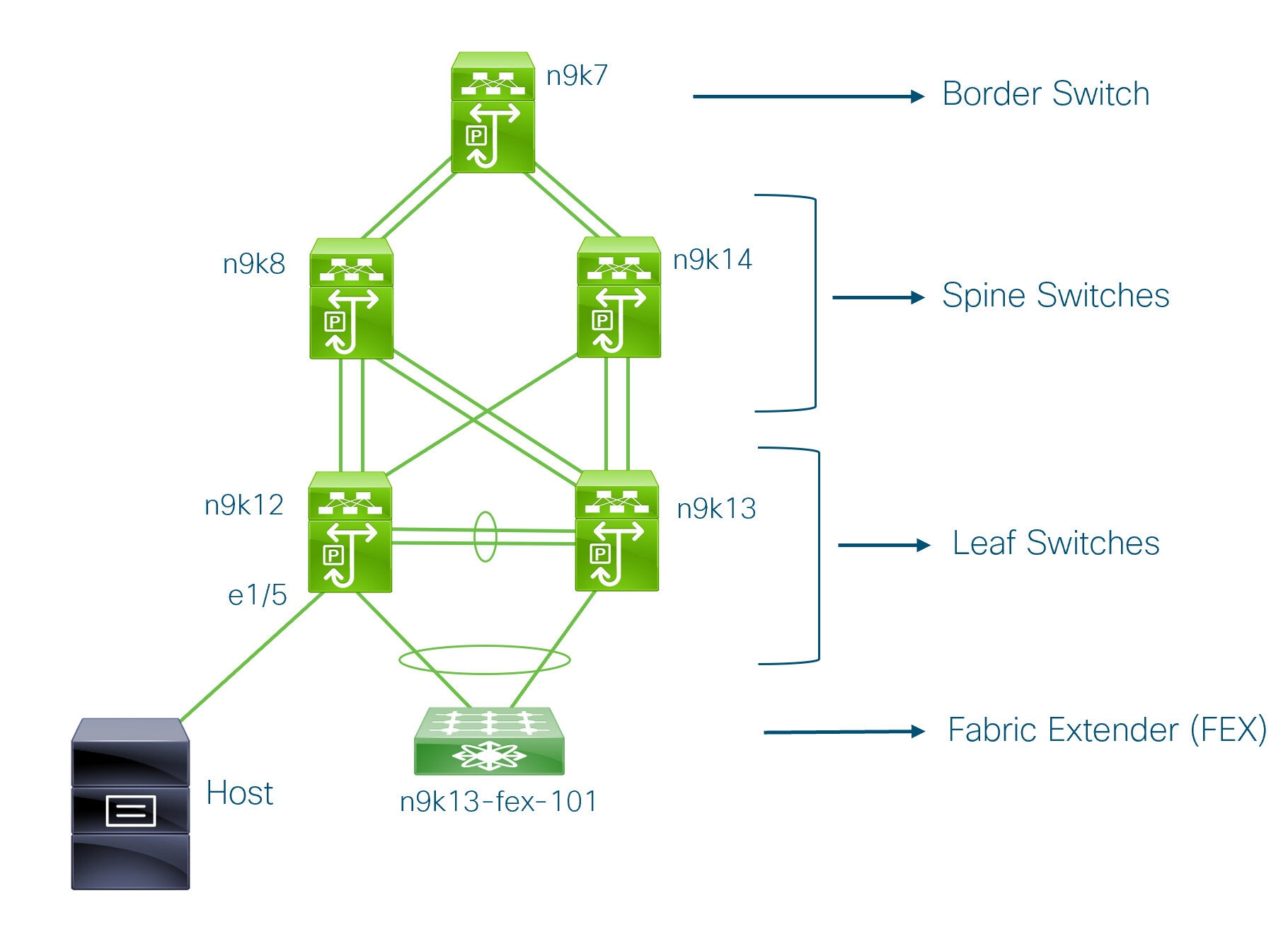
You can see that there is a border switch, two spine switches, two leaf switches, and a Fabric Extender or FEX.
A host is connected to the n9k12 leaf switch through the interface Ethernet 1/5.
NDFC Brownfield Deployment Tasks
The following tasks are involved in a Brownfield migration:
Verifying the Existing VXLAN BGP EVPN Fabric
Let us check the network connectivity of the n9k12 switch from the console terminal.
-
Verify the Network Virtual Interface or NVE in the fabric.
n9k12# show nve vni summary
Codes: CP - Control Plane        DP - Data Plane
       UC - Unconfigured

Total CP VNIs: 84    [Up: 84, Down: 0]
Total DP VNIs: 0    [Up: 0, Down: 0]
There are 84 VNIs in the control plane and they are up. Before the Brownfield migration, make sure that all the VNIs are up.
-
Check consistency and failures of vPC.
n9k12# show vpc Legend: (*) - local vPC is down, forwarding via vPC peer-link vPC domain id : 2 Peer status : peer adjacency formed ok vPC keep-alive status : peer is alive Configuration consistency status : success Per-vlan consistency status : success Type-2 consistency status : success vPC role : secondary Number of vPCs configured : 40 Peer Gateway : Enabled Dual-active excluded VLANs : - Graceful Consistency Check : Enabled Auto-recovery status : Enabled, timer is off.(timeout = 300s) Delay-restore status : Timer is off.(timeout = 60s) Delay-restore SVI status : Timer is off.(timeout = 10s) Operational Layer3 Peer-router : Disabled . . . -
Check the EVPN neighbors of the n9k-12 switch.
n9k12# show bgp l2vpn evpn summary
BGP summary information for VRF default, address family L2VPN EVPN
BGP router identifier 192.168.0.4, local AS number 65000
BGP table version is 637, L2VPN EVPN config peers 2, capable peers 2
243 network entries and 318 paths using 57348 bytes of memory
BGP attribute entries [234/37440], BGP AS path entries [0/0]
BGP community entries [0/0], BGP clusterlist entries [2/8]

Neighbor        V    AS MsgRcvd MsgSent   TblVer  InQ OutQ Up/Down  State/PfxRcd
192.168.0.0     4 65000     250      91      637    0    0 01:26:59 75
192.168.0.1     4 65000     221      63      637    0    0 00:57:22 75
You can see that there are two neighbors corresponding to the spine switches.
Note that the ASN is 65000.
-
Verify the VRF information.
n9k12# show run vrf internet

!Command: show running-config vrf Internet
!Running configuration last done at: Fri Aug  9 01:38:02 2019
!Time: Fri Aug  9 02:48:03 2019

version 7.0(3)I7(6) Bios:version 07.59

interface Vlan347
  vrf member Internet

interface Vlan349
  vrf member Internet

interface Vlan3962
  vrf member Internet

interface Ethernet1/25
  vrf member Internet

interface Ethernet1/26
  vrf member Internet
vrf context Internet
  description Internet
  vni 16777210
  ip route 204.90.141.0/24 204.90.140.129 name LC-Networks
  rd auto
  address-family ipv4 unicast
    route-target both auto
    route-target both auto evpn
router ospf 300
  vrf Internet
    router-id 204.90.140.3
    redistribute direct route-map allow
    redistribute static route-map static-to-ospf
router bgp 65000
  vrf Internet
    address-family ipv4 unicast
      advertise l2vpn evpn
The VRF Internet is configured on this switch.
The host connected to the n9k-12 switch is part of the VRF Internet.
You can see the VLANs associated with this VRF.
Specifically, the host is part of Vlan349.
-
Verify the layer 3 interface information.
n9k12# show run interface vlan349

!Command: show running-config interface Vlan349
!Running configuration last done at: Fri Aug  9 01:38:02 2019
!Time: Fri Aug  9 02:49:27 2019

version 7.0(3)I7(6) Bios:version 07.59

interface Vlan349
  no shutdown
  vrf member Internet
  no ip redirects
  ip address 204.90.140.134/29
  no ipv6 redirects
  fabric forwarding mode anycast-gateway
Note that the IP address is 204.90.140.134. This IP address is configured as the anycast gateway IP.
-
Verify the physical interface information. This switch is connected to the Host through the interface Ethernet 1/5.
n9k12# show run interface ethernet1/5

!Command: show running-config interface Ethernet1/5
!Running configuration last done at: Fri Aug  9 01:38:02 2019
!Time: Fri Aug  9 02:50:05 2019

version 7.0(3)I7(6) Bios:version 07.59

interface Ethernet1/5
  description to host
  switchport mode trunk
  switchport trunk native vlan 349
  switchport trunk allowed vlan 349,800,815
  spanning-tree bpduguard enable
  mtu 9050
You can see that this interface is connected to the host and is configured with VLAN 349.
-
Verify the connectivity from the host to the anycast gateway IP address.
host# ping 204.90.140.134 count unlimited interval 1
PING 204.90.140.134 (204.90.140.134): 56 data bytes
64 bytes from 204.90.140.134: icmp_seq=0 ttl=254 time=1.078 ms
64 bytes from 204.90.140.134: icmp_seq=1 ttl=254 time=1.129 ms
64 bytes from 204.90.140.134: icmp_seq=2 ttl=254 time=1.151 ms
64 bytes from 204.90.140.134: icmp_seq=3 ttl=254 time=1.162 ms
64 bytes from 204.90.140.134: icmp_seq=4 ttl=254 time=1.84 ms
64 bytes from 204.90.140.134: icmp_seq=5 ttl=254 time=1.258 ms
64 bytes from 204.90.140.134: icmp_seq=6 ttl=254 time=1.273 ms
64 bytes from 204.90.140.134: icmp_seq=7 ttl=254 time=1.143 ms
We let the ping command run in the background while we transition the existing brownfield fabric into Nexus Dashboard Fabric Controller.
Creating a VXLAN EVPN Fabric Using the Data Center VXLAN EVPN Template
This topic describes how to create a new VXLAN EVPN fabric using the Data Center VXLAN EVPN template and contains descriptions for the IPv4 underlay.
You can create a Data Center VXLAN EVPN fabric with IPv6 only underlay. The IPv6 underlay is supported only for the Data Center VXLAN EVPN template. For information about the IPv6 underlay, see Configuring a VXLANv6 Fabric.
-
Navigate to the LAN Fabrics page:
Manage > Fabrics
-
Click Actions > Create Fabric.
The Create Fabric window appears.
-
Enter a unique name for the fabric in the Fabric Name field, then click Choose Fabric.
A list of all available fabric templates are listed.
-
From the available list of fabric templates, choose the Data Center VXLAN EVPN template, then click Select.
-
Enter the necessary field values to create a fabric.
The tabs and their fields in the screen are explained in the following sections. The overlay and underlay network parameters are included in these tabs.
If you’re creating a standalone fabric as a potential member fabric of an MSD fabric (used for provisioning overlay networks for fabrics that are connected through EVPN Multi-Site technology), see VXLAN EVPN Multi-Site before creating the member fabric.
-
When you have completed the necessary configurations, click Save.
-
Click on the fabric to display a summary in the slide-in pane.
-
Click on the Launch icon to display the Fabric Overview.
-
General Parameters
The General Parameters tab is displayed by default. The fields in this tab are described in the following table.
| Field | Description |
|---|---|
|
BGP ASN |
Enter the BGP AS number the fabric is associated with. This must be same as existing fabric. |
|
Enable IPv6 Underlay |
Enable the IPv6 underlay feature. For information, see the section "Configuring a VXLANv6 Fabric" in Data Center VXLAN EVPN_. |
|
Enable IPv6 Link-Local Address |
Enables the IPv6 Link-Local address. |
|
Fabric Interface Numbering |
Specifies whether you want to use point-to-point (p2p) or unnumbered networks. |
|
Underlay Subnet IP Mask |
Specifies the subnet mask for the fabric interface IP addresses. |
|
Underlay Subnet IPv6 Mask |
Specifies the subnet mask for the fabric interface IPv6 addresses. |
|
Underlay Routing Protocol |
The IGP used in the fabric, OSPF, or IS-IS. |
|
Route-Reflectors (RRs) |
The number of spine switches that are used as route reflectors for transporting BGP traffic. Choose 2 or 4 from the drop-down box. The default value is 2. To deploy spine devices as RRs, Nexus Dashboard Fabric Controller sorts the spine devices based on their serial numbers, and designates two or four spine devices as RRs. If you add more spine devices, existing RR configuration won’t change. Increasing the count - You can increase the route reflectors from two to four at any point in time. Configurations are automatically generated on the other two spine devices designated as RRs. Decreasing the count - When you reduce four route reflectors to two, remove the unneeded route reflector devices from the fabric. Follow these steps to reduce the count from 4 to 2.
You can preselect RRs and RPs before performing the first Save & Deploy operation. For more information, see Preselecting Switches as Route-Reflectors and Rendezvous-Points. |
|
Anycast Gateway MAC |
Specifies the anycast gateway MAC address. |
|
Enable Performance Monitoring |
Check the check box to enable performance monitoring. Ensure that you do not clear interface counters from the Command Line Interface of the switches. Clearing interface counters can cause the Performance Monitor to display incorrect data for traffic utilization. If you must clear the counters and the switch has both |
What’s next: Complete the configurations in another tab if necessary, or click Save when you have completed the necessary configurations for this fabric.
Replication
The fields in the Replication tab are described in the following table. Most of the fields are automatically generated based on Cisco-recommended best practice configurations, but you can update the fields if needed.
| Field | Description |
|---|---|
|
Replication Mode |
The mode of replication that is used in the fabric for BUM (Broadcast, Unknown Unicast, Multicast) traffic. The choices are Ingress Replication or Multicast. When you choose Ingress replication, the multicast related fields get disabled. You can change the fabric setting from one mode to the other, if no overlay profile exists for the fabric. |
|
Multicast Group Subnet |
IP address prefix used for multicast communication. A unique IP address is allocated from this group for each overlay network. The replication mode change isn’t allowed if a policy template instance is created for the current mode. For example, if a multicast related policy is created and deployed, you can’t change the mode to Ingress. |
|
Enable Tenant Routed Multicast (TRM) |
Check the check box to enable Tenant Routed Multicast (TRM) that allows overlay multicast traffic to be supported over EVPN/MVPN in the VXLAN BGP EVPN fabric. |
|
Default MDT Address for TRM VRFs |
The multicast address for Tenant Routed Multicast traffic is populated. By default, this address is from the IP prefix specified in the Multicast Group Subnet field. When you update either field, ensure that the TRM address is chosen from the IP prefix specified in Multicast Group Subnet. For more information, see the section "Overview of Tenant Routed Multicast" in Configuring Tenant Routed Multicast. |
|
Rendezvous-Points |
Enter the number of spine switches acting as rendezvous points. |
|
RP mode |
Choose from the two supported multicast modes of replication, ASM (for Any-Source Multicast [ASM]) or BiDir (for Bidirectional PIM [BIDIR-PIM]). When you choose ASM, the BiDir related fields aren’t enabled. When you choose BiDir, the BiDir related fields are enabled.
BIDIR-PIM is supported on Cisco’s Cloud Scale Family platforms 9300-EX and 9300-FX/FX2, and software release 9.2(1) onwards. When you create a new VRF for the fabric overlay, this address is populated in the Underlay Multicast Address field, in the Advanced tab. |
|
Underlay RP Loopback ID |
The loopback ID used for the rendezvous point (RP), for multicast protocol peering purposes in the fabric underlay. |
|
Underlay Primary RP Loopback ID |
Enabled if you choose BIDIR-PIM as the multicast mode of replication. The primary loopback ID used for the phantom RP, for multicast protocol peering purposes in the fabric underlay. |
|
Underlay Backup RP Loopback ID |
Enabled if you choose BIDIR-PIM as the multicast mode of replication. The secondary loopback ID used for the phantom RP, for multicast protocol peering purposes in the fabric underlay. |
|
Underlay Second Backup RP Loopback Id |
Used for the second fallback Bidir-PIM Phantom RP. |
|
Underlay Third Backup RP Loopback Id |
Used for the third fallback Bidir-PIM Phantom RP. |
What’s next: Complete the configurations in another tab if necessary, or click Save when you have completed the necessary configurations for this fabric.
VPC
The fields in the VPC tab are described in the following table. Most of the fields are automatically generated based on Cisco-recommended best practice configurations, but you can update the fields if needed.
| Field | Description |
|---|---|
|
vPC Peer Link VLAN |
VLAN used for the vPC peer link SVI. |
|
Make vPC Peer Link VLAN as Native VLAN |
Enables vPC peer link VLAN as Native VLAN. |
|
vPC Peer Keep Alive option |
Choose the management or loopback option. If you want to use IP addresses assigned to the management port and the management VRF, choose management. If you use IP addresses assigned to loopback interfaces (and a non-management VRF), choose loopback. If you use IPv6 addresses, you must use loopback IDs. |
|
vPC Auto Recovery Time |
Specifies the vPC auto recovery time-out period in seconds. |
|
vPC Delay Restore Time |
Specifies the vPC delay restore period in seconds. |
|
vPC Peer Link Port Channel ID |
Specifies the Port Channel ID for a vPC Peer Link. By default, the value in this field is 500. |
|
vPC IPv6 ND Synchronize |
Enables IPv6 Neighbor Discovery synchronization between vPC switches. The check box is enabled by default. Uncheck the check box to disable the function. |
|
vPC advertise-pip |
Select the check box to enable the Advertise PIP feature. You can enable the advertise PIP feature on a specific vPC as well. . |
|
Enable the same vPC Domain Id for all vPC Pairs |
Enable the same vPC Domain ID for all vPC pairs. When you select this field, the vPC Domain Id field is editable. |
|
vPC Domain Id |
Specifies the vPC domain ID to be used on all vPC pairs. |
|
vPC Domain Id Range |
Specifies the vPC Domain Id range to use for new pairings. |
|
Enable QoS for Fabric vPC-Peering |
Enable QoS on spines for guaranteed delivery of vPC Fabric Peering communication.
QoS for vPC fabric peering and queuing policies options in fabric settings are mutually exclusive. |
|
QoS Policy Name |
Specifies QoS policy name that should be same on all fabric vPC peering spines. The default name is spine_qos_for_fabric_vpc_peering. |
What’s next: Complete the configurations in another tab if necessary, or click Save when you have completed the necessary configurations for this fabric.
Protocols
The fields in the Protocols tab are described in the following table. Most of the fields are automatically generated based on Cisco-recommended best practice configurations, but you can update the fields if needed.
| Field | Description |
|---|---|
|
Underlay Routing Loopback Id |
The loopback interface ID is populated as 0 since loopback0 is usually used for fabric underlay IGP peering purposes. |
|
Underlay VTEP Loopback Id |
The loopback interface ID is populated as 1 since loopback1 is used for the VTEP peering purposes. |
|
Underlay Anycast Loopback Id |
The loopback interface ID is greyed out and used for vPC Peering in VXLANv6 Fabrics only. |
|
Underlay Routing Protocol Tag |
The tag defining the type of network. |
|
OSPF Area ID |
The OSPF area ID, if OSPF is used as the IGP within the fabric.
The OSPF or IS-IS authentication fields are enabled based on your selection in the Underlay Routing Protocol field in the General tab. |
|
Enable OSPF Authentication |
Select the check box to enable OSPF authentication. Deselect the check box to disable it. If you enable this field, the OSPF Authentication Key ID and OSPF Authentication Key fields get enabled. |
|
OSPF Authentication Key ID |
The Key ID is populated. |
|
OSPF Authentication Key |
The OSPF authentication key must be the 3DES key from the switch.
Plain text passwords are not supported. Log in to the switch, retrieve the encrypted key and enter it in this field. Refer, Retrieving the Authentication Key section for details. |
|
IS-IS Level |
Select the IS-IS level from this drop-down list. |
|
Enable IS-IS Network Point-to-Point |
Enables network point-to-point on fabric interfaces which are numbered. |
|
Enable IS-IS Authentication |
Select the check box to enable IS-IS authentication. Deselect the check box to disable it. If you enable this field, the IS-IS authentication fields are enabled. |
|
IS-IS Authentication Keychain Name |
Enter the Keychain name, such as CiscoisisAuth. |
|
IS-IS Authentication Key ID |
The Key ID is populated. |
|
IS-IS Authentication Key |
Enter the Cisco Type 7 encrypted key.
Plain text passwords are not supported. Log in to the switch, retrieve the encrypted key and enter it in this field. Refer the Retrieving the Authentication Key section for details. |
|
Set IS-IS Overload Bit |
When enabled, set the overload bit for an elapsed time after a reload. |
|
IS-IS Overload Bit Elapsed Time |
Allows you to clear the overload bit after an elapsed time in seconds. |
|
Enable BGP Authentication |
Select the check box to enable BGP authentication. Deselect the check box to disable it. If you enable this field, the BGP Authentication Key Encryption Type and BGP Authentication Key fields are enabled.
If you enable BGP authentication using this field, leave the iBGP Peer-Template Config field blank to avoid duplicate configuration. |
|
BGP Authentication Key Encryption Type |
Choose the 3 for 3DES encryption type, or 7 for Cisco encryption type. |
|
BGP Authentication Key |
Enter the encrypted key based on the encryption type.
Plain text passwords are not supported. Log in to the switch, retrieve the encrypted key and enter it in the BGP Authentication Key field. Refer the Retrieving the Authentication Key section for details. |
|
Enable PIM Hello Authentication |
Select this check box to enable PIM hello authentication on all the intra-fabric interfaces of the switches in a fabric. This check box is editable only for the Multicast replication mode. Note this check box is valid only for the IPv4 underlay. |
|
PIM Hello Authentication Key |
Specifies the PIM hello authentication key. For more information, see Retrieving PIM Hello Authentication Key. To retrieve the PIM Hello Authentication Key, perform the following steps:
|
|
Enable BFD |
Check the check box to enable feature bfd on all switches in the fabric. This feature is valid only on IPv4 underlay and the scope is within a fabric. BFD within a fabric is supported natively. The BFD feature is disabled by default in the Fabric Settings. If enabled, BFD is enabled for the underlay protocols with the default settings. Any custom required BFD configurations must be deployed via the per switch freeform or per interface freeform policies. The following config is pushed after you select the Enable BFD check box: For information about BFD feature compatibility, refer your respective platform documentation and for information about the supported software images, see Compatibility Matrix for Cisco. |
|
Enable BFD for iBGP |
Check the check box to enable BFD for the iBGP neighbor. This option is disabled by default. |
|
Enable BFD for OSPF |
Check the check box to enable BFD for the OSPF underlay instance. This option is disabled by default, and it is grayed out if the link state protocol is ISIS. |
|
Enable BFD for ISIS |
Check the check box to enable BFD for the ISIS underlay instance. This option is disabled by default, and it is grayed out if the link state protocol is OSPF. |
|
Enable BFD for PIM |
Check the check box to enable BFD for PIM. This option is disabled by default, and it is be grayed out if the replication mode is Ingress.Following are examples of the BFD global policies: |
|
Enable BFD Authentication |
Check the check box to enable BFD authentication. If you enable this field, the BFD Authentication Key ID and BFD Authentication Key fields are editable.
BFD Authentication is not supported when the Fabric Interface Numbering field under the General tab is set to unnumbered. The BFD authentication fields will be grayed out automatically. BFD authentication is valid for only for P2P interfaces. |
|
BFD Authentication Key ID |
Specifies the BFD authentication key ID for the interface authentication. The default value is 100. |
|
BFD Authentication Key |
Specifies the BFD authentication key. For information about how to retrieve the BFD authentication parameters. |
|
iBGP Peer-Template Config |
Add iBGP peer template configurations on the leaf switches to establish an iBGP session between the leaf switch and route reflector. If you use BGP templates, add the authentication configuration within the template and uncheck the Enable BGP Authentication check box to avoid duplicate configuration. In the sample configuration, the 3DES password is displayed after password 3. The following fields can be used to specify different configurations:
In a brownfield migration, if the spine and leaf use different peer template names, both iBGP Peer-Template Config and Leaf/Border/Border Gateway iBGP Peer-Template Config fields need to be set according to the switch config. If spine and leaf use the same peer template name and content (except for the "route-reflector-client" CLI), only iBGP Peer-Template Config field in fabric setting needs to be set. If the fabric settings on iBGP peer templates do not match the existing switch configuration, an error message is generated and the migration will not proceed. |
What’s next: Complete the configurations in another tab if necessary, or click Save when you have completed the necessary configurations for this fabric.
Advanced
The fields in the Advanced tab are described in the following table. Most of the fields are automatically generated based on Cisco-recommended best practice configurations, but you can update the fields if needed.
| Field | Description |
|---|---|
|
VRF Template |
Specifies the VRF template for creating VRFs. |
|
Network Template |
Specifies the network template for creating networks. |
|
VRF Extension Template |
Specifies the VRF extension template for enabling VRF extension to other fabrics. |
|
Network Extension Template |
Specifies the network extension template for extending networks to other fabrics. |
|
Overlay Mode |
VRF/Network configuration using config-profile or CLI, default is config-profile. For more information, see Overlay Mode. |
|
Enable L3VNI w/o VLAN |
Beginning with NDFC release 12.2.1, check the box to enable the Layer 3 VNI without VLAN feature. The setting at this fabric-level field affects the related field at the VRF level. For more information, see:
|
|
Site ID |
The ID for this fabric if you are moving this fabric within an MSD. The site ID is mandatory for a member fabric to be a part of an MSD. Each member fabric of an MSD has a unique site ID for identification. |
|
Intra Fabric Interface MTU |
Specifies the MTU for the intra fabric interface. This value should be an even number. |
|
Layer 2 Host Interface MTU |
Specifies the MTU for the layer 2 host interface. This value should be an even number. |
|
Unshut Host Interfaces by Default |
Check this check box to unshut the host interfaces by default. |
|
Power Supply Mode |
Choose the appropriate power supply mode. |
|
CoPP Profile |
Choose the appropriate Control Plane Policing (CoPP) profile policy for the fabric. By default, the strict option is populated. |
|
VTEP HoldDown Time |
Specifies the NVE source interface hold down time. |
|
Brownfield Overlay Network Name Format |
Enter the format to be used to build the overlay network name during a brownfield import or migration. The network name should not contain any white spaces or special characters except underscore () and hyphen (-). The network name must not be changed once the brownfield migration has been initiated. See the _Creating Networks for the Standalone Fabric section for the naming convention of the network name. The syntax is [<string> | $$VLAN_ID$$] $$VNI$$ [<string>| $$VLAN_ID$$] and the default value is Auto_Net_VNI$$VNI$$_VLAN$$VLAN_ID$$. When you create networks, the name is generated according to the syntax you specify. The following list describes the variables in the syntax:
An example overlay network name: Site_VNI12345_VLAN1234
Ignore this field for greenfield deployments. The Brownfield Overlay Network Name Format applies for the following brownfield imports:
|
|
Enable CDP for Bootstrapped Switch |
Enables CDP on management (mgmt0) interface for bootstrapped switch. By default, for bootstrapped switches, CDP is disabled on the mgmt0 interface. |
|
Enable VXLAN OAM |
Enables the VXLAM OAM functionality for devices in the fabric. This is enabled by default. Uncheck the check box to disable VXLAN OAM function. If you want to enable the VXLAN OAM function on specific switches and disable on other switches in the fabric, you can use freeform configurations to enable OAM and disable OAM in the fabric settings.
The VXLAN OAM feature in Cisco Nexus Dashboard Fabric Controller is only supported on a single fabric or site. |
|
Enable Tenant DHCP |
Check the check box to enable feature dhcp and associated configurations globally on all switches in the fabric. This is a pre-requisite for support of DHCP for overlay networks that are part of the tenant VRFs.
Ensure that Enable Tenant DHCP is enabled before enabling DHCP-related parameters in the overlay profiles. |
|
Enable NX-API |
Specifies enabling of NX-API on HTTPS. This check box is checked by default. |
|
Enable NX-API on HTTP Port |
Specifies enabling of NX-API on HTTP. Enable this check box and the Enable NX-API check box to use HTTP. This check box is checked by default. If you uncheck this check box, the applications that use NX-API and supported by Cisco Nexus Dashboard Fabric Controller, such as Endpoint Locator (EPL), Layer 4-Layer 7 services (L4-L7 services), VXLAN OAM, and so on, start using the HTTPS instead of HTTP.
If you check the Enable NX-API check box and the Enable NX-API on HTTP check box, applications use HTTP. |
|
Enable Policy-Based Routing (PBR) |
Check this check box to enable routing of packets based on the specified policy. Starting with Cisco NX-OS Release 7.0(3)I7(1) and later releases, this feature works on Cisco Nexus 9000 Series switches with Nexus 9000 Cloud Scale (Tahoe) ASICs. This feature is used along with the Layer 4-Layer 7 service workflow. For information on Layer 4-Layer 7 service, refer the Layer 4-Layer 7 Service chapter. |
|
Enable Strict Config Compliance |
Enable the Strict Config Compliance feature by selecting this check box. It enables bi-directional compliance checks to flag additional configs in the running config that are not in the intent/expected config. By default, this feature is disabled. |
|
Enable AAA IP Authorization |
Enables AAA IP authorization, when IP Authorization is enabled in the remote authentication server. This is required to support Nexus Dashboard Fabric Controller in scenarios where customers have strict control of which IP addresses can have access to the switches. |
|
Enable NDFC as Trap Host |
Select this check box to enable Nexus Dashboard Fabric Controller as an SNMP trap destination. Typically, for a native HA Nexus Dashboard Fabric Controller deployment, the eth1 VIP IP address will be configured as SNMP trap destination on the switches. By default, this check box is enabled. |
|
Anycast Border Gateway advertise-pip |
Enables to advertise Anycast Border Gateway PIP as VTEP. Effective on MSD fabric 'Recalculate Config'. |
|
Greenfield Cleanup Option |
Enable the switch cleanup option for switches imported into Nexus Dashboard Fabric Controller with Preserve-Config=No, without a switch reload. This option is typically recommended only for the fabric environments with Cisco Nexus 9000v Switches to improve on the switch clean up time. The recommended option for Greenfield deployment is to employ Bootstrap or switch cleanup with a reboot. In other words, this option should be unchecked. |
|
Enable Precision Time Protocol (PTP) |
Enables PTP across a fabric. When you check this check box, PTP is enabled globally and on core-facing interfaces. Additionally, the PTP Source Loopback Id and PTP Domain Id fields are editable. For more information, see the section "Precision Time Protocol for Data Center VXLAN EVPN Fabrics" in Precision Time Protocol for Data Center VXLAN EVPN Fabrics. |
|
PTP Source Loopback Id |
Specifies the loopback interface ID Loopback that is used as the Source IP Address for all PTP packets. The valid values range from 0 to 1023. The PTP loopback ID cannot be the same as RP, Phantom RP, NVE, or MPLS loopback ID. Otherwise, an error will be generated. The PTP loopback ID can be the same as BGP loopback or user-defined loopback which is created from Nexus Dashboard Fabric Controller. If the PTP loopback ID is not found during Deploy Config, the following error is generated: Loopback interface to use for PTP source IP is not found. Create PTP loopback interface on all the devices to enable PTP feature. |
|
PTP Domain Id |
Specifies the PTP domain ID on a single network. The valid values range from 0 to 127. |
|
Enable MPLS Handoff |
Check the check box to enable the MPLS Handoff feature. For more information, see MPLS SR and LDP Handoff. |
|
Underlay MPLS Loopback Id |
Specifies the underlay MPLS loopback ID. The default value is 101. |
|
Enable TCAM Allocation |
TCAM commands are automatically generated for VXLAN and vPC Fabric Peering when enabled. |
|
Enable Default Queuing Policies |
Check this check box to apply QoS policies on all the switches in this fabric. To remove the QoS policies that you applied on all the switches, uncheck this check box, update all the configurations to remove the references to the policies, and save and deploy. Pre-defined QoS configurations are included that can be used for various Cisco Nexus 9000 Series Switches. When you check this check box, the appropriate QoS configurations are pushed to the switches in the fabric. The system queuing is updated when configurations are deployed to the switches. You can perform the interface marking with defined queuing policies, if required, by adding the required configuration to the per interface freeform block. Review the actual queuing policies by opening the policy file in the template editor. From Cisco Nexus Dashboard Fabric Controller Web UI, choose Manage > Templates. Search for the queuing policies by the policy file name, for example, queuing_policy_default_8q_cloudscale. Choose the file. From the Actions drop-down list, select Edit template content to edit the policy. See the Cisco Nexus 9000 Series NX-OS Quality of Service Configuration Guide for platform specific details. |
|
N9K Cloud Scale Platform Queuing Policy |
Choose the queuing policy from the drop-down list to be applied to all Cisco Nexus 9200 Series Switches and the Cisco Nexus 9000 Series Switches that ends with EX, FX, and FX2 in the fabric. The valid values are queuing_policy_default_4q_cloudscale and queuing_policy_default_8q_cloudscale. Use the queuing_policy_default_4q_cloudscale policy for FEXes. You can change from the queuing_policy_default_4q_cloudscale policy to the queuing_policy_default_8q_cloudscale policy only when FEXes are offline. |
|
N9K R-Series Platform Queuing Policy |
Choose the queuing policy from the drop-down list to be applied to all Cisco Nexus switches that ends with R in the fabric. The valid value is queuing_policy_default_r_series. |
|
Other N9K Platform Queuing Policy |
Choose the queuing policy from the drop-down list to be applied to all other switches in the fabric other than the switches mentioned in the above two options. The valid value is queuing_policy_default_other. |
|
Enable AI/ML QOS and Queuing Policies |
Beginning with NDFC release 12.2.1, check the box to enable AI/ML QoS and queuing policies in the BGP fabric. For more information, see AI/ML QoS Classification and Queuing Policies.
This option is not available if you also enabled either of the following options:
|
|
AI / ML QOS & Queuing Policy |
This field is available if you checked the Enable AI/ML QOS and Queuing Policies option above. Beginning with NDFC release 12.2.1, choose the queuing policy from the drop-down list based on the predominant fabric link speed for certain switches in the fabric. For more information, see AI/ML QoS Classification and Queuing Policies. Options are:
|
|
Enable MACsec |
Enables MACsec for the fabric. For more information, Enabling MACsec. Freeform CLIs - Fabric level freeform CLIs can be added while creating or editing a fabric. They are applicable to switches across the fabric. You must add the configurations as displayed in the running configuration, without indentation. Switch level freeform configurations should be added via the switch freeform on NDFC. For more information, see Enabling Freeform Configurations on Fabric Switches. |
|
Leaf Freeform Config |
Add CLIs that should be added to switches that have the Leaf,Border, and Border Gateway roles. |
|
Spine Freeform Config |
Add CLIs that should be added to switches with a Spine, Border Spine, Border Gateway Spine, and Super Spine roles. |
|
Intra-fabric Links Additional Config |
Add CLIs that should be added to the intra-fabric links. |
What’s next: Complete the configurations in another tab if necessary, or click Save when you have completed the necessary configurations for this fabric.
Resources
The fields in the Resources tab are described in the following table. Most of the fields are automatically generated based on Cisco-recommended best practice configurations, but you can update the fields if needed.
| Field | Description |
|---|---|
|
Manual Underlay IP Address Allocation |
Do not check this check box if you are transitioning your VXLAN fabric management to Nexus Dashboard Fabric Controller.
|
|
Underlay Routing Loopback IP Range |
Specifies loopback IP addresses for the protocol peering. |
|
Underlay VTEP Loopback IP Range |
Specifies loopback IP addresses for VTEPs. |
|
Underlay RP Loopback IP Range |
Specifies the anycast or phantom RP IP address range. |
|
Underlay Subnet IP Range |
IP addresses for underlay P2P routing traffic between interfaces. |
|
Underlay MPLS Loopback IP Range |
Specifies the underlay MPLS loopback IP address range. For eBGP between Border of Easy A and Easy B, Underlay routing loopback and Underlay MPLS loopback IP range must be a unique range. It should not overlap with IP ranges of the other fabrics, else VPNv4 peering will not come up. |
|
Underlay Routing Loopback IPv6 Range |
Specifies Loopback0 IPv6 Address Range |
|
Underlay VTEP Loopback IPv6 Range |
Specifies Loopback1 and Anycast Loopback IPv6 Address Range. |
|
Underlay Subnet IPv6 Range |
Specifies IPv6 Address range to assign Numbered and Peer Link SVI IPs. |
|
BGP Router ID Range for IPv6 Underlay |
Specifies BGP router ID range for IPv6 underlay. |
|
Layer 2 VXLAN VNI Range |
Specifies the overlay VXLAN VNI range for the fabric (min:1, max:16777214). |
|
Layer 3 VXLAN VNI Range |
Specifies the overlay VRF VNI range for the fabric (min:1, max:16777214). |
|
Network VLAN Range |
VLAN range for the per switch overlay network (min:2, max:4094). |
|
VRF VLAN Range |
VLAN range for the per switch overlay Layer 3 VRF (min:2, max:4094). |
|
Subinterface Dot1q Range |
Specifies the subinterface range when L3 sub interfaces are used. |
|
VRF Lite Deployment |
Specify the VRF Lite method for extending inter fabric connections. The VRF Lite Subnet IP Range field specifies resources reserved for IP address used for VRF Lite when VRF Lite IFCs are auto-created. If you select Back2Back&ToExternal, then VRF Lite IFCs are auto-created. |
|
Auto Deploy for Peer |
This check box is applicable for VRF Lite deployment. When you select this checkbox, auto-created VRF Lite IFCs will have the Auto Generate Configuration for Peer field in the VRF Lite tab set. To access VRF Lite IFC configuration, navigate to the Links tab, select the particular link, and then choose Actions > Edit. You can check or uncheck the check box when the VRF Lite Deployment field is not set to Manual. This configuration only affects the new auto-created IFCs and does not affect the existing IFCs. You can edit an auto-created IFC and check or uncheck the Auto Generate Configuration for Peer field. This setting takes priority always. |
|
Auto Deploy Default VRF |
When you select this check box, the Auto Generate Configuration on default VRF field is automatically enabled for auto-created VRF Lite IFCs. You can check or uncheck this check box when the VRF Lite Deployment field is not set to Manual. The Auto Generate Configuration on default VRF field when set, automatically configures the physical interface for the border device, and establishes an EBGP connection between the border device and the edge device or another border device in a different VXLAN EVPN fabric. |
|
Auto Deploy Default VRF for Peer |
When you select this check box, the Auto Generate Configuration for NX-OS Peer on default VRF field is automatically enabled for auto-created VRF Lite IFCs. You can check or uncheck this check box when the VRF Lite Deployment field is not set to Manual. The Auto Generate Configuration for NX-OS Peer on default VRF field when set, automatically configures the physical interface and the EBGP commands for the peer NX-OS switch.
To access the Auto Generate Configuration on default VRF and Auto Generate Configuration for NX-OS Peer on default VRF fields for an IFC link, navigate to the Links tab, select the particular link and choose Actions > Edit. |
|
Redistribute BGP Route-map Name |
Defines the route map for redistributing the BGP routes in default VRF. |
|
VRF Lite Subnet IP Range and VRF Lite Subnet Mask |
These fields are populated with the DCI subnet details. Update the fields, as needed. The values shown in your screen are automatically generated. If you want to update the IP address ranges, VXLAN Layer 2/Layer 3 network ID ranges or the VRF/Network VLAN ranges, ensure the following:
When you update a range of values, ensure that it does not overlap with other ranges. You should only update one range of values at a time. If you want to update more than one range of values, do it in separate instances. For example, if you want to update L2 and L3 ranges, you should do the following.
|
|
Service Network VLAN Range |
Specifies a VLAN range in the Service Network VLAN Range field. This is a per switch overlay service network VLAN range. The minimum allowed value is 2 and the maximum allowed value is 3967. |
|
Auto Allocation of Unique IP on VRF Extension over VRF Lite IFC |
Automatically allocates a unique IPv4 address with subnet for the source and the destination interfaces for VRF extensions over VRF Lite IFC. When enabled, the system auto populates a unique IP address for the source and the destination interfaces for each extension in the VRF attachment. When you disable the feature, the system auto populates the same IP address for the source and the destination interfaces for the VRF extensions and these IP addresses are allocated in resource manager with the VRFs attached. The resource manager ensures that they are not used for any other purpose on the same VRF. |
|
Per VRF Per VTEP Loopback Auto-Provisioning |
Auto provisions a loopback address in IPv4 format for a VTEP that the system uses for VRF attachment. This option is not enabled by default. When enabled, the system allocates an IPv4 address from the IP pool that you have assigned for the VTEP loopback interface. |
|
Per VRF Per VTEP IP Pool for Loopback |
A pool of IP addresses assigned to the loopback interfaces on VTEPs for each VRF. |
|
Route Map Sequence Number Range |
Specifies the route map sequence number range. The minimum allowed value is 1 and the maximum allowed value is 65534. |
What’s next: Complete the configurations in another tab if necessary, or click Save when you have completed the necessary configurations for this fabric.
Manageability
The fields in the Manageability tab are described in the following table. Most of the fields are automatically generated based on Cisco-recommended best practice configurations, but you can update the fields if needed.
| Field | Description |
|---|---|
|
Inband Management |
Enabling this allows the management of the switches over their front panel interfaces. The Underlay Routing Loopback interface is used for discovery. If enabled, switches cannot be added to the fabric over their out-of-band (OOB) mgmt0 interface. To manage easy fabrics through Inband management, ensure that you have chosen Data in NDFC Web UI, Admin > System Settings > Server Settings > Admin. Both inband management and out-of-band connectivity (mgmt0) are supported for this setting. For more information, see the section "Inband Management and Inband POAP in Easy Fabrics" in Configuring Inband Management, Inband POAP Management, and Secure POAP. |
|
DNS Server IPs |
Specifies the comma separated list of IP addresses (v4/v6) of the DNS servers. |
|
DNS Server VRFs |
Specifies one VRF for all DNS servers or a comma separated list of VRFs, one per DNS server. |
|
NTP Server IPs |
Specifies comma separated list of IP addresses (v4/v6) of the NTP server. |
|
NTP Server VRFs |
Specifies one VRF for all NTP servers or a comma separated list of VRFs, one per NTP server. |
|
Syslog Server IPs |
Specifies the comma separated list of IP addresses (v4/v6) IP address of the syslog servers, if used. |
|
Syslog Server Severity |
Specifies the comma separated list of syslog severity values, one per syslog server. The minimum value is 0 and the maximum value is 7. To specify a higher severity, enter a higher number. |
|
Syslog Server VRFs |
Specifies one VRF for all syslog servers or a comma separated list of VRFs, one per syslog server. |
|
AAA Freeform Config |
Specifies the AAA freeform configurations. If AAA configurations are specified in the fabric settings, switch_freeform PTI with source as UNDERLAY_AAA and description as AAA Configurations will be created. |
What’s next: Complete the configurations in another tab if necessary, or click Save when you have completed the necessary configurations for this fabric.
Bootstrap
The fields in the Bootstrap tab are described in the following table. Most of the fields are automatically generated based on Cisco-recommended best practice configurations, but you can update the fields if needed.
| Field | Description |
|---|---|
|
Enable Bootstrap |
Select this check box to enable the bootstrap feature. Bootstrap allows easy day-0 import and bring-up of new devices into an existing fabric. Bootstrap leverages the NX-OS POAP functionality. Starting from Cisco NDFC Release 12.1.1e, to add more switches and for POAP capability, chose check box for Enable Bootstrap and Enable Local DHCP Server. For more information, see the section "Inband Management and Inband POAP in Easy Fabrics" in Configuring Inband Management, Inband POAP Management, and Secure POAP. After you enable bootstrap, you can enable the DHCP server for automatic IP address assignment using one of the following methods:
|
|
Enable Local DHCP Server |
Select this check box to initiate enabling of automatic IP address assignment through the local DHCP server. When you select this check box, the DHCP Scope Start Address and DHCP Scope End Address fields become editable. If you do not select this check box, Nexus Dashboard Fabric Controller uses the remote or external DHCP server for automatic IP address assignment. |
|
DHCP Version |
Select DHCPv4 or DHCPv6 from this drop-down list. When you select DHCPv4, the Switch Mgmt IPv6 Subnet Prefix field is disabled. If you select DHCPv6, the Switch Mgmt IP Subnet Prefix is disabled.
Cisco Nexus 9000 and 3000 Series Switches support IPv6 POAP only when switches are either Layer-2 adjacent (eth1 or out-of-band subnet must be a /64) or they are L3 adjacent residing in some IPv6 /64 subnet. Subnet prefixes other than /64 are not supported. |
|
DHCP Scope Start Address and DHCP Scope End Address |
Specifies the first and last IP addresses of the IP address range to be used for the switch out of band POAP. |
|
Switch Mgmt Default Gateway |
Specifies the default gateway for the management VRF on the switch. |
|
Switch Mgmt IP Subnet Prefix |
Specifies the prefix for the Mgmt0 interface on the switch. The prefix should be between 8 and 30. DHCP scope and management default gateway IP address specification - If you specify the management default gateway IP address 10.0.1.1 and subnet mask 24, ensure that the DHCP scope is within the specified subnet, between 10.0.1.2 and 10.0.1.254. |
|
Switch Mgmt IPv6 Subnet Prefix |
Specifies the IPv6 prefix for the Mgmt0 interface on the switch. The prefix should be between 112 and 126. This field is editable if you enable IPv6 for DHCP. |
|
Enable AAA Config |
Select this check box to include AAA configurations from the Manageability tab as part of the device start-up config post bootstrap. |
|
DHCPv4/DHCPv6 Multi Subnet Scope |
Specifies the field to enter one subnet scope per line. This field is editable after you check the Enable Local DHCP Server check box. The format of the scope should be defined as: DHCP Scope Start Address, DHCP Scope End Address, Switch Management Default Gateway, Switch Management Subnet Prefix For example: 10.6.0.2, 10.6.0.9, 10.6.0.1, 24 |
|
Bootstrap Freeform Config |
(Optional) Enter additional commands as needed. For example, if you require some additional configurations to be pushed to the device and be available post device bootstrap, they can be captured in this field, to save the desired intent. After the devices boot up, they will contain the configuration defined in the Bootstrap Freeform Config field. Copy-paste the running-config to a freeform config field with correct indentation, as seen in the running configuration on the NX-OS switches. The freeform config must match the running config. For more information, see Enabling Freeform Configurations on Fabric Switches. |
What’s next: Complete the configurations in another tab if necessary, or click Save when you have completed the necessary configurations for this fabric.
Configuration Backup
The fields in the Configuration Backup tab are described in the following table. Most of the fields are automatically generated based on Cisco-recommended best practice configurations, but you can update the fields if needed.
| Field | Description |
|---|---|
|
Hourly Fabric Backup |
Select the check box to enable an hourly backup of fabric configurations and the intent. The hourly backups are triggered during the first 10 minutes of the hour. |
|
Scheduled Fabric Backup |
Check the check box to enable a daily backup. This backup tracks changes in running configurations on the fabric devices that are not tracked by configuration compliance. |
|
Scheduled Time |
Specify the scheduled backup time in a 24-hour format. This field is enabled if you check the Scheduled Fabric Backup check box. Select both the check boxes to enable both back up processes. The backup process is initiated after you click Save. The scheduled backups are triggered exactly at the time you specify with a delay of up to two minutes. The scheduled backups are triggered regardless of the configuration deployment status. The number of fabric backups that will be retained on NDFC is decided by the Admin > System Settings > Server Settings > LAN Fabric > Maximum Backups per Fabric.The number of archived files that can be retained is set in the # Number of archived files per device to be retained: field in the Server Properties window.
To trigger an immediate backup, do the following:
You can also initiate the fabric backup in the fabric topology window. Click Backup Now in the Actions pane. |
What’s next: Complete the configurations in another tab if necessary, or click Save when you have completed the necessary configurations for this fabric.
Flow Monitor
The fields in the Flow Monitor tab are described in the following table. Most of the fields are automatically generated based on Cisco-recommended best practice configurations, but you can update the fields if needed.
| Field | Description |
|---|---|
|
Enable Netflow |
Check this check box to enable Netflow on VTEPs for this fabric. By default, Netflow is disabled. When enabled, NetFlow configuration will be applied to all VTEPS that support netflow.
When Netflow is enabled on the fabric, you can choose not to have netflow on a particular switch by having a dummy no_netflow PTI. If netflow is not enabled at the fabric level, an error message is generated when you enable netflow at the interface, network, or vrf level. For information about Netflow support for Cisco NDFC, see section "Netflow Support" in Understanding LAN Fabrics. |
In the Netflow Exporter area, choose Actions > Add to add one or more Netflow exporters. This exporter is the receiver of the netflow data. The fields on this screen are:
-
Exporter Name - Specifies the name of the exporter.
-
IP - Specifies the IP address of the exporter.
-
VRF - Specifies the VRF over which the exporter is routed.
-
Source Interface - Specifies the source interface name.
-
UDP Port - Specifies the UDP port over which the netflow data is exported.
Click Save to configure the exporter. Click Cancel to discard. You can also choose an existing exporter and choose Actions > Edit or Actions > Delete to perform relevant actions.
In the Netflow Record area, click Actions > Add to add one or more Netflow records. The fields on this screen are:
-
Record Name - Specifies the name of the record.
-
Record Template - Specifies the template for the record. Enter one of the record templates names. In Release 12.0.2, the following two record templates are available for use. You can create custom netflow record templates. Custom record templates saved in the template library are available for use here.
-
netflow_ipv4_record - Uses the IPv4 record template.
-
netflow_l2_record - Uses the Layer 2 record template.
-
-
Is Layer2 Record - Check this check box if the record is for Layer2 netflow.
Click Save to configure the report. Click Cancel to discard. You can also choose an existing record and select Actions > Edit or Actions > Delete to perform relevant actions.
In the Netflow Monitor area, click Actions > Add to add one or more Netflow monitors. The fields on this screen are:
-
Monitor Name - Specifies the name of the monitor.
-
Record Name - Specifies the name of the record for the monitor.
-
Exporter1 Name - Specifies the name of the exporter for the netflow monitor.
-
Exporter2 Name - (optional) Specifies the name of the secondary exporter for the netflow monitor.
The record name and exporters referred to in each netflow monitor must be defined in "Netflow Record" and "Netflow Exporter".
Click Save to configure the monitor. Click Cancel to discard. You can also choose an existing monitor and select Actions > Edit or Actions > Delete to perform relevant actions.
What’s next: Complete the configurations in another tab if necessary, or click Save when you have completed the necessary configurations for this fabric.
Adding Switches and Transitioning VXLAN Fabric Management to NDFC
Let us discover and add switches to the newly created fabric.
-
Double click on the newly created fabric to view the Fabric Overview screen.
Click on Switches tab.
-
From the Actions drop-down list, select Add Switches.
The Add Switches window appears.
Similarly, you can add switches on Topology window. On Topology window, choose a fabric, right-click on a fabric and click Add Switches.
-
On the Add Switches - Fabric screen, enter the Seed Switch Details.
Enter the IP address of the switch in the Seed IP field. Enter the username and password of the switches that you want to discover.
By default, the value in the Max Hops field is 2. The switch with the specified IP address and the switches that are 2 hops from it will be populated after the discovery is complete.
Make sure to check the Preserve Config check box. This ensures that the current configuration of the switches will be retained.
-
Click Discover Switches.
The switch with the specified IP address and switches up to two hops away (depending on the setting of Max Hops) from it are populated in the Scan Details section.
-
Check the check box next to the switches that have to be imported into the fabric and click Import into fabric.
It is best practice to discover multiple switches at the same time in a single attempt. The switches must be cabled and connected to the NDFC server and the switch status must be manageable.
If switches are imported in multiple attempts, then please ensure that all the switches are added to the fabric before proceeding with the Brownfield import process.
-
Click Import into fabric.
The switch discovery process is initiated. The Progress column displays progress for all the selected switches. It displays done for each switch after completion.
You should not close the screen and try to import switches again until all selected switches are imported or an error message comes up.
If an error message comes up, close the screen. The fabric topology screen comes up. The error messages are displayed at the top-right part of the screen. Resolve the errors and initiate the import process again by clicking Add Switches in the Actions panel.
-
After a successful import, the progress bar shows Done for all the switches. Click Close.
After closing the window, the fabric topology window comes up again. The switch is in Migration Mode now, and the Migration mode label is displayed on the switch icons.
At this point, you must not try to add Greenfield or new switches. Support is not available for adding new switches during the migration process. It might lead to undesirable consequences for your network. However, you can add a new switch after the migration process is complete.
-
After all the network elements are discovered, they are displayed in the Topology window in a connected topology. Each switch is assigned the Leaf role by default.
The switch discovery process might fail for a few switches, and the Discovery Error message is displayed. However, such switches are still displayed in the fabric topology. You should remove such switches from the fabric (Right-click the switch icon and click Discovery > Remove from fabric), and import them again.
You should not proceed to the next step until all switches in the existing fabric are discovered in NDFC.
If you choose the Hierarchical layout for display (in the Actions panel), the topology automatically gets aligned as per role assignment, with the leaf switches at the bottom, the spine switches connected on top of them, and the border switches at the top.
The supported roles for switches with the Cisco NX-OS Release 7.0(3)I4(8b) and 7.0(4)I4(x) images are Border Leaf, Border Spine, Leaf, and Spine
-
Select the switch, click Actions > Set Role. On the Select Role screen, select Border and click Select.
Similarly, set the Spine role for the n9k-14 and n9k-8 spine switches.
You need to manually create a vPC pairing when the L3 keep alive is configured on the switches. Otherwise, the vPC configuration is automatically picked up from the switches.
vPC Pairing - The vPC pairing must be done for switches where the Layer 3 vPC peer-keep alive is used. The vPC configuration is automatically picked up from the switches when the vPC peer keep alive is established through the management option. This pairing reflects in the GUI only after the migration is complete.
-
Right-click the switch icon and click vPC Pairing to set a vPC switch pair.
The Select vPC peer screen comes up. It lists potential vPC peer switches.
-
Select the appropriate switch and click OK. The fabric topology comes up again. The vPC pair is formed.
Check if you have added all switches from the current fabric. If you have missed adding switches, add them now. Once you are certain that you have imported all existing switches, move to the next step, the Save and Deploy option.
-
-
From the Fabric Overview Actions drop-down list, choose Recalculate and Deploy.
When you click Recalculate and Deploy, NDFC obtains switch configurations and populates the state of every switch from the current running configuration to the current expected configuration, which is the intended state maintained in NDFC.
If there are configuration mismatches, Pending Config column shows the number of lines of difference. Click on the Pending Config column to view the Pending Config and Side-by-Side Comparison of the running configuration. Click Deploy to apply the configurations.
After the migration of underlay and overlay networks, the Deploy Configuration screen comes up.
-
The brownfield migration requires best practices to be followed on the existing fabric such as maintain consistency of the overlay configurations.
-
The Brownfield migration may take some time to complete since it involves collecting the running configuration from switches, build the NDFC configuration intent based on these, consistency checks etc.
-
Any errors or inconsistencies that are found during the migration is reported in fabric errors. The switches continue to remain in the Migration mode. You should fix these errors and complete the migration again by clicking Deploy until no errors are reported.
-
-
After the configurations are generated, review them by clicking the links in the Preview Config column.
We strongly recommend that you preview the configuration before proceeding to deploy it on the switches. Click the Preview Configuration column entry. The Preview Config screen comes up. It lists the pending configurations on the switch.
The Side-by-side Comparison tab displays the running configuration and expected configuration side-by-side.
The Pending Config tab displays the set of configurations that need to be deployed on a switch in order to go from the current running configuration to the current expected or intended configuration.
The Pending Config tab may show many configuration lines that will be deployed to the switches. Typically, on a successful brownfield import, these lines correspond to the configuration profiles pushed to the switches for a overlay network configuration. Note that the existing network and VRF-related overlay configurations are not removed from the switches.
The configuration profiles are NDFC required constructs for managing the VXLAN configurations on the switches. During the Brownfield import process, they capture the same information as the original VXLAN configurations already present on the switches. In the following image, the configuration profile with vlan 160 is applied.
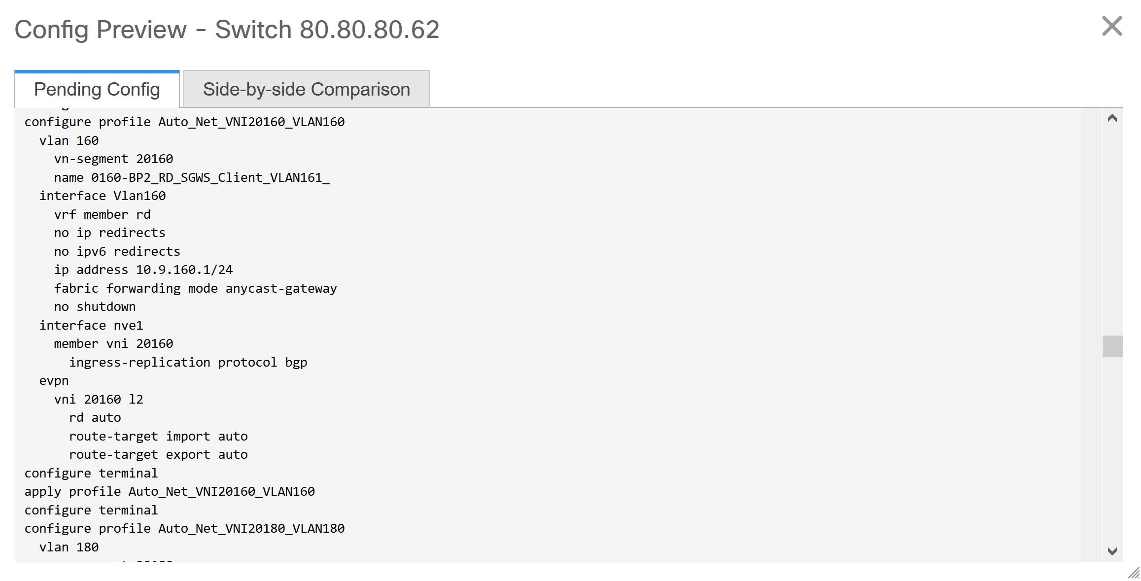
As part of the import process, after the configuration profiles are applied, the original CLI based configuration references will be removed from the switches. These are the 'no' CLIs that will be seen towards the end of the diffs. The VXLAN configurations on the switches will be persisted in the configuration profiles. In the following image, you can see that the configurations will be removed, specifically, no vlan 160.
The removal of CLI based configuration is allowed if the Overlay Mode is set to config-profile, and not CLI.
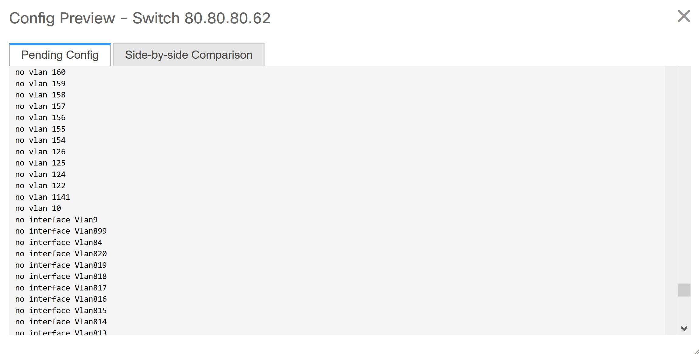
The Side-by-side Comparison tab displays the Running Config and Expected Config on the switch.
-
Close the Config Preview Switch window after reviewing the configurations.
-
Click Deploy Config to deploy the pending configuration onto the switches.
If the Status column displays FAILED, investigate the reason for failure to address the issue.
The progress bar shows 100% for each switch. After correct provisioning and successful configuration compliance, close the screen.
In the fabric topology screen that comes up, all imported switch instances are displayed in green color, indicating successful configuration. Also, the Migration Mode label is not displayed on any switch icon.
NDFC has successfully imported a VXLAN-EVPN fabric.
Post-transitioning of VXLAN fabric management to NDFC - This completes the transitioning process of VXLAN fabric management to NDFC. Now, you can add new switches and provision overlay networks for your fabric. For details, refer the respective section in the Fabrics topic in the configuration guide.
For more information, see About Fabric Overview for LAN Operational Mode Setups.
Configuration Profiles Support for Brownfield Migration
Cisco NDFC supports the Brownfield import of fabrics with VXLAN overlay provisioned with configuration profiles. This import process recreates the overlay configuration intent based on the configuration profiles. The underlay migration is performed with the usual Brownfield migration.
This feature can be used to recover your existing Easy fabric when a NDFC backup is not available to be restored. In this case, you must install the latest NDFC release, create a fabric, and then import the switches into the fabric.
Note that this feature is not recommended for the NDFC upgrade. For more information, see Cisco NDFC Installation and Upgrade Guide.
The following are the guidelines for the support of configuration profiles:
-
The Brownfield migration of configuration profiles is supported for the Data Center VXLAN EVPN template.
-
The configuration profiles on the switches must be a subset of the default overlay Universal profiles. If extra configuration lines are present that are not part of the Universal profiles, unwanted profile refreshes will be seen. In this case, after you recaluclate and deploy configuration, review the diffs using the Side-by-side Comparison feature and deploy the changes.
-
Brownfield migration with switches having a combination of VXLAN overlay configuration profiles and regular CLIs is not supported. If this condition is detected, an error is generated, and migration is aborted. All the overlays must be with either configuration profiles or regular CLIs only.
Manually Adding PIM-BIDIR Configuration for Leaf or Spine Post Brownfield Migration
After brownfield migration, if you add new spine or leaf switches, you should manually configure the PIM-BIDIR feature.
The following procedure shows how to manually configure the PIM-BIDIR feature for a new Leaf or Spine:
-
Check the base_pim_bidir_11_1 policies that are created for an RP added through the brownfield migration. Check the RP IP and Multicast Group used in each ip pim rp-address_RP_IP_group-list_MULTICAST_GROUP_bidir command.
-
Add respective base_pim_bidir_11_1 policies from the View/Edit Policies window for the new Leaf or Spine, push the config for each base_pim_bidir_11_1 policy.
Migrating a VXLAN EVPN Multi-Site Fabric with Border Gateway Switches
When you migrate an existing VXLAN EVPN Multi-Site fabric with a border gateway switch into NDFC, make sure to note the following guidelines:
-
Uncheck all Auto IFC creation related fabric settings. Review the settings and ensure they are unchecked as follows:
-
Data Center VXLAN EVPN fabric
Uncheck Auto Deploy Both check box under Resources tab.
-
VXLAN EVPN Multi-Site fabric
Uncheck Multi-Site Underlay IFC Auto Deployment Flag check box under DCI tab.
-
-
Underlay Multisite peering: The eBGP peering and corresponding routed interfaces for underlay extensions between sites are captured in switch_freeform and routed_inerfaces, and optionally in the interface_freeform configs. This configuration includes all the global configs for multisite. Loopbacks for EVPN multisite are also captured via the appropriate interface templates.
-
Overlay Multisite peering: The eBGP peering is captured as part of switch_freeform as the only relevant config is under router bgp.
-
Overlays containing Networks or VRFs: The corresponding intent is captured with the profiles on the Border Gateways with extension_type = MULTISITE.
-
Create all the required fabrics including the Data Center VXLAN EVPN and Multi-Site Interconnect Network fabrics with the required fabric settings. Disable the Auto VRF-Lite options as mentioned above. For more information, refer to Creating VXLAN EVPN Fabric and External Fabric sections.
-
Import all the switches into all the required fabrics and set roles accordingly.
-
Click Recalculate and Deploy in each of the fabrics and ensure that the Brownfield Migration process reaches the 'Deployment' phase. Now, do not click Deploy Configuration.
-
Create the VXLAN EVPN Multi-Site fabric with the required fabric settings and disable the Auto MultiSite IFC options as shown in Guidelines. For more information, see Creating a VXLAN EVPN Multi-Site Fabric.
-
Move all the member fabrics into the VXLAN EVPN Multi-Site. Do not proceed further till this step is completed successfully. For more information, see Moving the Member1 Fabric Under VXLAN EVPN Multi-Site-Parent-Fabric.
The Overlay Networks and VRFs definitions in each of the Easy Fabrics must be symmetric for them to get added successfully to the VXLAN EVPN Multi-Site. Errors will be reported if any mismatches are found. These must be fixed by updating the overlay information in the fabric(s) and added to the VXLAN EVPN Multi-Site.
-
Create all the Multisite Underlay IFCs such that they match the IP address and settings of the deployed configuration.
Additional interface configurations must be added to the Source/Destination interface freeform fields in the Advanced section as needed.
For more information, see Configuring Multi-Site Overlay IFCs.
-
Create all the Multisite Overlay IFCs such that they match the IP address and settings of the deployed configuration. You will need to add the IFC links. For more information, see Configuring Multi-Site Overlay IFCs.
-
If there are VRF-Lite IFCs also, create them as well.
If the Brownfield Migration is for the case where Configuration Profiles already exist on the switches, the VRF-Lite IFCs will be created automatically in Step #3.
-
If Tenant Routed Multicast (TRM) is enabled in the VXLAN EVPN Multi-Site fabric, edit all the TRM related VRFs and Network entries in VXLAN EVPN Multi-Site and enable the TRM parameters.
This step needs to be performed if TRM is enabled in the fabric. If TRM is not enabled, you still need to edit each Network entry and save it.
-
Now click Recalculate and Deploy in the VXLAN EVPN Multi-Site fabric, but, do not click Deploy Configuration.
-
Navigate to each member fabric, click Recalculate and Deploy, and then click Deploy Configuration.
-
This completes the Brownfield Migration. You can now manage all the networks or VRFs for BGWs by using the regular NDFC Overlay workflows.
When you migrate an existing VXLAN EVPN Multi-Site fabric with border gateway switches (BGW) that has a Layer-3 port-channel for Underlay IFCs, make sure to do the following steps:
Ensure that the child fabrics are added into VXLAN EVPN Multi-Site before migrating an VXLAN EVPN Multi-Site fabric.
-
Click on appropriate VXLAN EVPN Multi-Site child fabric and navigate to FabricsInterfaces to view the BGW. Choose an appropriate Layer-3 port channel to use for underlay IFC.
-
On Policy column, choose int_port_channel_trunk_host_11_1 from drop-down list. Enter the associated port-channel interface members and then click Save.
-
Navigate to the Tabular view of the VXLAN EVPN Multi-Site fabric. Edit layer-3 port link, choose the multisite underlay IFC link template, enter source and destination IP addresses. These IP addresses are the same as existing configuration values on the switches
-
Do the steps from step 7 to 11 from above procedure.
Configuring a VXLANv6 Fabric
From Cisco NDFC, you can create a fabric with IPv6 only underlay. The IPv6 underlay is supported only for the Data Center VXLAN EVPN template. In the IPv6 underlay fabric, intra-fabric links, routing loopback, vPC peer link SVI, and NVE loopback interface for VTEP are configured with IPv6 addresses. EVPN BGP neighbor peering is also established using IPv6 addressing.
The following guidelines are applicable for IPv6 underlay:
-
IPv6 underlay is supported for the Cisco Nexus 9000 Series switches with Cisco NX-OS Release 9.3(1) or higher.
-
VXLANv6 is only supported Cisco Nexus 9332C, Cisco Nexus C9364C, and Cisco Nexus modules that end with EX, GX, FX, FX2, FX3, or FXP.
VXLANv6 is defined as a VXLAN fabric with IPv6 underlay.
-
In VXLANv6, the platforms supported on spine are all Nexus 9000 Series and Nexus 3000 Series platforms.
-
The overlay routing protocol supported for the IPv6 fabric is BGP EVPN.
-
vPC with physical multichassis EtherChannel trunk (MCT) feature is supported for the IPv6 underlay network in NDFC. The vPC peer keep-alive can be loopback or management with IPv4 or IPv6 address.
-
Brownfield migration is supported for the VXLANv6 fabrics. Note that L3 vPC keep-alive using IPv6 address is not supported for brownfield migration. This vPC configuration is deleted after the migration. However, L3 vPC keep-alive using IPv4 address is supported.
-
DHCPv6 is supported for the IPv6 underlay network.
-
The following features are not supported for VXLAN IPv6 underlay:
-
Multicast underlay
-
Tenant Routed Multicast (TRM)
-
ISIS, OSPF, and BGP authentication
-
VXLAN Multi-Site
-
Dual stack underlay
-
vPC Fabric Peering
-
DCI SR-MPLS or MPLS-LDP handoff
-
BFD
-
Super Spine switch roles
-
NGOAM
-
Creating VXLAN EVPN Fabric with IPv6 Underlay
This procedure shows how to create a VXLAN EVPN fabric with IPv6 underlay. Note that only the fields for creating a VXLAN fabric with IPv6 underlay are documented. For information about the remaining fields, see Creating a VXLAN EVPN Fabric Using the Data Center VXLAN EVPN Template.
-
Choose Manage > Fabrics.
-
From the Actions drop-down list, choose Create Fabric.
The Create Fabric window appears.
Fabric Name - Enter the name of the fabric.
Fabric Template - From the drop-down list, choose Data Center VXLAN EVPN.
-
The General Parameters tab is displayed by default. The fields in this tab are:
BGP ASN - Enter the BGP AS number for the fabric. You can enter either the 2 byte BGP ASN or 4 byte BGP ASN.
Enable IPv6 Underlay - Check the Enable IPv6 Underlay check box .
Enable IPv6 Link-Local Address - Check the Enable IPv6 Link-Local Address check box to use the link local addresses in the fabric between leaf-spine and spine-border interfaces. If you check this check box, the Underlay Subnet IPv6 Mask field is not editable. By default, the Enable IPv6 Link-Local Address field is enabled.
IPv6 underlay supports p2p networks only. Therefore, the Fabric Interface Numbering drop-down list is disabled.
Underlay Subnet IPv6 Mask - Specify the subnet mask for the fabric interface IPv6 addresses.
Underlay Routing Protocol - Specify the IGP used in the fabric, that is, OSPF or IS-IS for VXLANv6.
-
All the fields under the Replication tab are disabled.
IPv6 underlay supports ingress replication mode only.
-
Click the VPC tab.
vPC Peer Keep Alive option - Choose management or loopback. To use IP addresses assigned to the management port and the management VRF, choose management. To use IP addresses assigned to loopback interfaces and a non-management VRF, choose underlay routing loopback with IPv6 address for PKA. Both the options are supported for IPv6 underlay.
-
Click the Protocols tab.
Underlay Anycast Loopback Id - Specify the underlay anycast loopback ID for IPv6 underlay. You cannot configure IPv6 address as secondary, an additional loopback interface is allocated on each vPC device. Its IPv6 address is used as the VIP.
-
Click the Resources tab.
Manual Underlay IP Address Allocation: Check the check box to manually allocate underlay IP addresses. The dynamic underlay IP addresses fields are disabled.
Underlay Routing Loopback IPv6 Range: Specify loopback IPv6 addresses for protocol peering.
Underlay VTEP Loopback IPv6 Range: Specify loopback IPv6 addresses for VTEPs.
Underlay Subnet IPv6 Range: Specify the IPv6 address range that is used for assigning IP addresses for numbered and peer link SVIs. To edit this field, uncheck Enable IPv6 Link-Local Address check box under the General Parameters tab.
BGP Router ID Range for IPv6 Underlay: Specify the address range to assign BGP Router IDs. The IPv4 addressing is used for router with BGP and underlay routing protocols.
-
Click the Bootstrap tab.
Enable Bootstrap: Check the Enable Bootstrap check box. If this check box is not chosen, none of the other fields on this tab are editable.
Enable Local DHCP Server: Check the check box to initiate automatic assignment of IP addresses assignment through the local DHCP server. The DHCP Scope Start Address and DHCP Scope End Address fields are editable only after you check this check box.
DHCP Version: Choose DHCPv4 from the drop-down list.
-
Click Save to complete the creation of the fabric.
See the section "Adding Switches to a Fabric" in Add Switches for LAN Operational Mode.
Copyright
THE SPECIFICATIONS AND INFORMATION REGARDING THE PRODUCTS IN THIS MANUAL ARE SUBJECT TO CHANGE WITHOUT NOTICE. ALL STATEMENTS, INFORMATION, AND RECOMMENDATIONS IN THIS MANUAL ARE BELIEVED TO BE ACCURATE BUT ARE PRESENTED WITHOUT WARRANTY OF ANY KIND, EXPRESS OR IMPLIED. USERS MUST TAKE FULL RESPONSIBILITY FOR THEIR APPLICATION OF ANY PRODUCTS.
THE SOFTWARE LICENSE AND LIMITED WARRANTY FOR THE ACCOMPANYING PRODUCT ARE SET FORTH IN THE INFORMATION PACKET THAT SHIPPED WITH THE PRODUCT AND ARE INCORPORATED HEREIN BY THIS REFERENCE. IF YOU ARE UNABLE TO LOCATE THE SOFTWARE LICENSE OR LIMITED WARRANTY, CONTACT YOUR CISCO REPRESENTATIVE FOR A COPY.
The Cisco implementation of TCP header compression is an adaptation of a program developed by the University of California, Berkeley (UCB) as part of UCB’s public domain version of the UNIX operating system. All rights reserved. Copyright © 1981, Regents of the University of California.
NOTWITHSTANDING ANY OTHER WARRANTY HEREIN, ALL DOCUMENT FILES AND SOFTWARE OF THESE SUPPLIERS ARE PROVIDED “AS IS" WITH ALL FAULTS. CISCO AND THE ABOVE-NAMED SUPPLIERS DISCLAIM ALL WARRANTIES, EXPRESSED OR IMPLIED, INCLUDING, WITHOUT LIMITATION, THOSE OF MERCHANTABILITY, FITNESS FOR A PARTICULAR PURPOSE AND NONINFRINGEMENT OR ARISING FROM A COURSE OF DEALING, USAGE, OR TRADE PRACTICE.
IN NO EVENT SHALL CISCO OR ITS SUPPLIERS BE LIABLE FOR ANY INDIRECT, SPECIAL, CONSEQUENTIAL, OR INCIDENTAL DAMAGES, INCLUDING, WITHOUT LIMITATION, LOST PROFITS OR LOSS OR DAMAGE TO DATA ARISING OUT OF THE USE OR INABILITY TO USE THIS MANUAL, EVEN IF CISCO OR ITS SUPPLIERS HAVE BEEN ADVISED OF THE POSSIBILITY OF SUCH DAMAGES.
Any Internet Protocol (IP) addresses and phone numbers used in this document are not intended to be actual addresses and phone numbers. Any examples, command display output, network topology diagrams, and other figures included in the document are shown for illustrative purposes only. Any use of actual IP addresses or phone numbers in illustrative content is unintentional and coincidental.
The documentation set for this product strives to use bias-free language. For the purposes of this documentation set, bias-free is defined as language that does not imply discrimination based on age, disability, gender, racial identity, ethnic identity, sexual orientation, socioeconomic status, and intersectionality. Exceptions may be present in the documentation due to language that is hardcoded in the user interfaces of the product software, language used based on RFP documentation, or language that is used by a referenced third-party product.
Cisco and the Cisco logo are trademarks or registered trademarks of Cisco and/or its affiliates in the U.S. and other countries. To view a list of Cisco trademarks, go to this URL: http://www.cisco.com/go/trademarks. Third-party trademarks mentioned are the property of their respective owners. The use of the word partner does not imply a partnership relationship between Cisco and any other company. (1110R)
© 2017-2024 Cisco Systems, Inc. All rights reserved.