
New and Changed Information
The following table provides an overview of the significant changes up to this current release. The table does not provide an exhaustive list of all changes or of the new features up to this release.
| Release Version | Feature | Description |
|---|---|---|
|
NDFC release 12.2.1 |
Support for automatically importing a pre-provisioned device to a fabric using PowerOn Auto Provisioning (POAP) |
When you enable this feature, NDFC automatically imports the pre-provisioned device to the fabric using POAP. You enable this feature using the Auto admit pre-provisioned switches during re-poap option on the Admin > System Settings > Server Settings > LAN-Fabric tab. With this feature, you can avoid having to reenter a username, password, and the bootstrap parameters on the Add Switches (Bootstrap) page. For more information, see Automatically Importing a Pre-provisioned Device Using POAP. |
|
NDFC release 12.2.1 |
Support added for waiting for a switch to change modes from normal to maintenance mode and vice versa |
When you enable this feature and you perform a switch change mode request from NDFC, the specified switch goes to maintenance mode and the NDFC GUI waits until the mode is completely changed on the switch. After the NDFC GUI completes the switch change mode request, the switch changes mode to maintenance or normal mode based on your selection. You enable the Wait for switch mode change to maintenance on deploy option from the Fabric Overview > Switches page, the Actions drop-down list on the Manage > Inventory > Switches page, or by double-clicking on a fabric to access a switch on the Topology page. You can then right-click on the switch and click More > Change Mode to access the Change Mode dialog box. For more information, see Waiting for a Switch to Change Modes. |
Switches
The following table describes the fields that appear on Switches window.
| Field | Description |
|---|---|
|
Switch |
Specifies name of the switch. |
|
IP Address |
Specifies IP address of the switch. |
|
Role |
Specifies role assigned on the switch. |
|
Serial Number |
Specifies the serial number of the switch. |
|
Fabric Name |
Specifies the associated fabric name for the switch. |
|
Config Status |
Specifies the configuration status.Status will be either In-Sync or Out-of-sync. |
|
Oper Status |
Specifies the configuration status.Status will be either In-Sync or Out-of-sync. |
|
Discovery Status |
Specifies the discovery status of the switch. |
|
Model |
Specifies the switch model. |
|
vPC Role |
Specifies the vPC role of the switch. |
|
vPC Peer |
Specifies the vPC peer of the switch. |
Adding Switches to a Fabric
UI Path: Manage > Inventory > Switches > Actions > Add Switches
Switches in each fabric are unique, and hence, only one switch can be added to one fabric.

Cisco Nexus Dashboard has two logical interfaces per node: management interface (bond1br) and fabric (also known as data) interface (bond0br). For Cisco Nexus Dashboard Fabric Controller, Nexus Dashboard management and fabric interfaces must be in different IP subnets. By default, the route for Nexus Dashboard services is through the fabric interface. An operator must add static routes on Nexus Dashboard Management Network to connect with switches that must be reached over a management interface (bond1br). This ensures that a route for the pods uses a management interface as the exit interface.
When performing discovery or adding switches or LAN credentials to NDFC, make sure that the switch user has the network-admin role.
SNMPv3 is used to discover Nexus devices. When a user is created on the switch, the same username/password is used by default for SNMPv3 authentication.
To add switches to the existing fabric, perform this procedure:
-
From Nexus Dashboard Fabric Controller Web UI, choose Manage > Inventory > Switches.
-
On Switches tab, Choose Actions > Add Switches.
The Add Switches window appears.
Similarly, you can add switches on the Topology window. On this window, choose a fabric, right-click the fabric, and click Add Switches.
-
On the Add Switches window, click Choose Fabric, click the appropriate fabric, and then click Select.
The Add Switches window has a default discover tab, and other tabs appear based on the fabric selected.
Also, you can pre-provision switches and interfaces. For more information, see pre-provision device and pre-provisioning ethernet interface.
NDFC supports switch discovery only for default system-name (serial number).
When Nexus Dashboard Fabric Controller discovers a switch with the hostname containing the period character (.), it is treated as a domain name and truncated. Only the text before the period character (.) is considered a hostname. For example:
-
If hostname is leaf.it.vxlan.bgp.org1-XYZ, Nexus Dashboard Fabric Controller shows only leaf
-
If hostname is leaf-itvxlan.bgp.org1-XYZ, Nexus Dashboard Fabric Controller shows only leafit-vxlan
Ensure that the switch name or the host name are unique within the fabric.
Discovering New Switches
Before discovering a new switch, verify that the password for that switch has eight characters or more. Even though NDFC allows you to discover a switch that has a password length of fewer than eight characters, you might see the error message "Unexpected error during post add processing" when adding a switch to an NDFC fabric when the password for that switch has fewer than eight characters.
-
When a new Cisco NX-OS device is powered on, typically that device has no startup configuration or any configuration state for that matter. Consequently, it powers on with NX-OS and post initialization, goes into a POAP loop. The device starts sending out DHCP requests on all the interfaces that are up including the mgmt0 interface.
-
As long as there is IP reachability between the device and the Nexus Dashboard Fabric Controller, the DHCP request from the device, will be forwarded to the Nexus Dashboard Fabric Controller. For easy day-0 device bring-up, the bootstrap options should be enabled on the Fabric Settings as mentioned earlier.
-
With bootstrap enabled for the fabric, the DHCP request coming from the device will be serviced by the Nexus Dashboard Fabric Controller. The temporary IP address allocated to the device by the Nexus Dashboard Fabric Controller will be employed to learn basic information about the switch including the device model, device NX-OS version, etc.
-
In the Nexus Dashboard Fabric Controller UI, choose Switch > Actions > Add Switches.
The Add Switches window appears with default tabs.
-
Choose Bootstrap(POAP) radio button.
As mentioned earlier, Nexus Dashboard Fabric Controller retrieves the serial number, model number, and version from the device and displays them on the Inventory Management along window. Also, an option to add the IP address, hostname, and password are made available. If the switch information is not retrieved, refresh the window.
At the top left part of the window, export and import options are provided to export and import the .csv file that contains the switch information. You can pre-provision devices using the import option as well.
From Cisco NDFC Release 12.1.1e, for pre-provisioned and bootstrap switches dummy values can be added for the serial number. After configuring the network successfully, serial number can be changed with the appropriate number of the switch on the Switches tab.
You can change serial number only for Nexus 9000 Series switches.
Select the checkbox next to the switch and enter the switch credentials: IP address and host name.
Based on the IP address of your device, you can either add the IPv4 or IPv6 address in the IP Address field.
You can provision devices in advance. To pre-provision devices, refer to Pre-provisioning device section.
-
In the Admin Password and Confirm Admin Password fields, enter and confirm the admin password.
This admin password is applicable for all the switches displayed in the POAP window.
You can specify a new user. Choose radio button Specify a new user enter Username, Password and choose Authentication Protocol from drop-down list.
If you do not want to use admin credentials to discover switches, you can instead use the AAA authentication, that is, RADIUS or TACACS credentials for discovery only.
-
(Optional) Use discovery credentials for discovering switches.
-
Click the Add Discovery Credentials icon to enter the discovery credentials for switches.
-
In the Discovery Credentials window, enter the discovery credentials such as discovery username and password.
Click OK to save the discovery credentials.
If the discovery credentials are not provided, Nexus Dashboard Fabric Controller uses the admin user and password to discover switches.
-
-
Click Bootstrap at the top right part of the screen.
Nexus Dashboard Fabric Controller provisions the management IP address and other credentials to the switch. In this simplified POAP process, all ports are opened up.
-
Click Refresh Topology to get updated information. The added switch goes through the POAP cycle. Monitor and check the switch for POAP completion.
-
After the added switch completes POAP, the fabric builder topology page is refreshed with the added switch thereby depicting its discovered physical connections. Set the appropriate role for the switch followed by a Deploy Config operation at the fabric level. The Fabric Settings, switch role, the topology etc. are evaluated by the Fabric Builder and the appropriate intended configuration for the switch is generated as part of the Save operation. The pending configuration will provide a list of the configurations that need to be deployed to the new switch in order to bring it IN-SYNC with the intent.
For any changes on the fabric that results in the Out-of-Sync, then you must deploy the changes. The process is the same as explained in the Discovering Existing Switches section.
During fabric creation, if you have entered AAA server information (in the Manageability tab), you must update the AAA server password on each switch. Else, switch discovery fails.
When discovering devices using SNMP, if you have configured to use an AAA server for authentication, the command sync-snmp-password <password> <username> is run on the switch through NDFC to generate a cached user. The authentication uses MD5, by default. You must specify the SNMPv3 authentication and Privacy protocol attributes in the switch AV-pair as follows:
snmpv3:auth=SHA priv=AES-128
-
After the pending configurations are deployed, the Progress column displays 100% for all switches.
-
Click Close to return to the fabric builder topology.
-
Click Refresh Topology to view the update. All switches must be in green color indicating that they are functional.
-
The switch and the link are discovered in Nexus Dashboard Fabric Controller. Configurations are built based on various policies (such as fabric, topology, and switch generated policies). The switch image (and other required) configurations are enabled on the switch.
-
In the Nexus Dashboard Fabric Controller GUI, the discovered switches can be seen in the Standalone fabric topology. Up to this step, the POAP is completed with basic settings. You must set up interfaces through the Manage > Inventory > Switches. Select a switch, then a slide-in pane appears. Click the Launch icon. On the Switches Overview tab, click the Interface tab for any additional configurations, but not limited to the following:
-
vPC pairing
-
Breakout interfaces
-
Port channels, and adding members to ports
When you enable or disable a vPC pairing/un-pairing or the advertise-pip option, or update Multi-Site configuration, you should use the Deploy Config operation. At the end of the operation, an error prompts you to configure the shutdown or no shutdown command on the nve interface. A sample error screenshot when you enable a vPC setup.
To resolve, go to the Interfaces > Actions > Deploy tab and deploy the Shutdown operation on the nve interface followed by a No Shutdown configuration. This is depicted in the figure below where the up arrow corresponds to a No Shutdown operation while a down arrow corresponds to a Shutdown operation.
-
You can right-click the switch to view various options:
-
Set Role - Assign a role to the switch (Spine, Border Gateway, and so on).
-
Changing of the switch role is allowed only before executing Deploy Config.
-
You can change the switch role from an existing role to a supported role if there are no overlays on the switches. Click Recalculate and Deploy to generate the updated configuration. These changes are allowed for a switch role:
-
Leaf to Border
-
Border to Leaf
-
Leaf to Border Gateway
-
Border Gateway to Leaf
-
Border to Border Gateway
-
Border Gateway to Border
-
Spine to Border Spine
-
Border Spine to Spine
-
Spine to Border Gateway Spine
-
Border Gateway Spine to Spine
-
Border Spine to Border Gateway Spine
-
Border Gateway Spine to Border Spine
-
-
You cannot change the switch role from any leaf role to any spine role or from any spine role to any leaf role.
-
Modes - Maintenance and Active/Operational modes.
-
vPC Pairing - Select a switch for vPC and then select its peer.
You can create a virtual link for a vPC pair or change the existing physical link to a virtual link for a vPC pair.
-
Manage Interfaces - Deploy configurations on the switch interfaces.
-
View/Edit Policies - See switch policies and edit them as required.
-
History - View per switch deployment history.
-
History - View per switch deployment and policy change history.
The Policy Change History tab lists the history of policies along with the users who made the changes like add, update, or delete.
Under the Policy Change History tab, for a policy, click Detailed History under the Generated Config column to view the generated config before and after.
The following table provides the summary of generated config before and after for Policy Template Instances (PTIs).
| PTI Operations | Generated Config Before | Generated Config After |
|---|---|---|
|
Add |
Empty |
Contains the config |
|
Update |
Contains config before changes |
Contains config after changes |
|
Mark-Delete |
Contains the config to be removed. |
Contains the config to be removed with color change. |
|
Delete |
Contains the config |
Empty |
When a policy or profile template is applied, an instance is created for each application of the template, which is known as Policy Template Instance or PTI.
-
Preview Config - View the pending configuration and the side-by-side comparison of the running and expected configuration.
-
Deploy Config - Deploy per switch configurations.
-
Discovery - You can use this option to update the credentials of the switch, reload the switch, rediscover the switch, and remove the switch from the fabric.
The new fabric is created, the fabric switches are discovered in Nexus Dashboard Fabric Controller, the underlay configuration provisioned on those switches, and the configurations between Nexus Dashboard Fabric Controller and the switches are synced. The remaining tasks are:
-
Provision interface configurations such as vPCs, loopback interface, and subinterface configurations.
-
Create networks and deploy them on the switches.
Discovering Existing Switches
To discover existing switches in Cisco Nexus Dashboard Fabric Controller Web UI, perform the following procedure:
-
After you click Add Switches, click Discover Switches to add one or more existing switches into the fabric.
In this case, a switch with known credentials and a pre-provisioned IP address, is added to the fabric.
-
The IP address (Seed IP), username, and password (Username and Password fields) of the switch are provided as the input by a user. The Preserve Config check box is chosen by default. This is the option that a user would select for a brownfield import of a device into the fabric. For a greenfield import where the device configuration will be cleaned up as part of the import process, the user should set the Preserve Config check box is not selected.
BGP Fabric does not support brownfield import of a device into the fabric.
-
Click Discover Switches.
The Add Switches window appears. Since the Max Hops field was populated with 2 (by default), the switch with the specified IP address (leaf-91) and switches two hops from that switch, are populated in the Add Switches result.
-
If the Cisco Nexus Dashboard Fabric Controller was able to perform a successful shallow discovery to a switch, the status column shows as Manageable. Choose the check box next to the appropriate switch(es) and click Add Switches.
Though this example describes the discovery of one switch, multiple switches can be discovered at once.
The switch discovery process is initiated. The Progress column displays progress for all the selected switches. It displays done for each switch on completion.
You must not close the screen (and try to add switches again) until all selected switches are imported or an error message comes up.
If an error message comes up, close the screen. The fabric topology screen comes up. The error messages are displayed at the top right part of the screen. Resolve the errors wherever applicable and initiate the import process again by clicking Add Switches in the Actions panel.
Cisco Nexus Dashboard Fabric Controller discovers all the switches, and the Progress column displays done for all switches, close the screen. The Standalone fabric topology screen comes up again. The switch icons of the added switches are displayed in it.
You will encounter the following errors during switch discovery sometimes.
-
Click Refresh topology to view the latest topology view.
When all switches are added and roles assigned to them, the fabric topology contains the switches and connections between them.
-
After discovering the devices, assign an appropriate role to each device. For more information on roles, see Assigning Switch Roles.
If you choose the Hierarchical layout for display (in the Actions panel), the topology automatically gets aligned as per role assignment, with the leaf devices at the bottom, the spine devices connected on top of them, and the border devices at the top.
Assign vPC switch role - To designate a pair of switches as a vPC switch pair, right-click the switch and choose the vPC peer switch from the list of switches.
AAA server password - During fabric creation, if you have entered AAA server information (in the Manageability tab), you must update the AAA server password on each switch. Else, switch discovery fails.
When a new vPC pair is created and deployed successfully using Cisco Nexus Dashboard Fabric Controller, one of the peers might be out-of-sync for the no ip redirects CLI even if the command exists on the switch. This out-of-sync is due to a delay on the switch to display the CLI in the running configuration, which causes a diff in the configuration compliance. Re-sync the switches in the Config Deployment window to resolve the diff.
-
Click Save.
The template and interface configurations form the underlay network configuration on the switches. Also, freeform CLIs that were entered as part of fabric settings (leaf and spine switch freeform configurations entered in the Advanced tab) are deployed.
Configuration Compliance: If the provisioned configurations and switch configurations do not match, the Status column displays out-of-sync. For example, if you enable a function on the switch manually through a CLI, then it results in a configuration mismatch.
To ensure configurations provisioned from Cisco Nexus Dashboard Fabric Controller to the fabric are accurate or to detect any deviations (such as out-of-band changes), Nexus Dashboard Fabric Controller’s Configuration Compliance engine reports and provides necessary remediation configurations.
When you click Deploy Config, the Config Deployment window appears.
If the status is out-of-sync, it suggests that there is inconsistency between the Nexus Dashboard Fabric Controller and configuration on the device.
The Re-sync button is displayed for each switch in the Re-sync column. Use this option to resynchronize Nexus Dashboard Fabric Controller state when there is a large scale out-of-band change, or if configuration changes do not register in the Nexus Dashboard Fabric Controller properly. The re-sync operation does a full CC run for the switch and recollects "show run" and "show run all" commands from the switch. When you initiate the re-sync process, a progress message is displayed on the screen. During the re-sync, the running configuration is taken from the switch. The Out-of-Sync/In-Sync status for the switch is recalculated based on the intent defined in Nexus Dashboard Fabric Controller.
Click the Preview Config column entry (updated with a specific number of lines). The Config Preview screen comes up.
The Pending Config tab displays the pending configurations for successful deployment.
The Side-by-side Comparison tab displays the current configurations and expected configurations together.
Multi-line banner motd configuration can be configured in Cisco Nexus Dashboard Fabric Controller with freeform configuration policy, either per switch using switch_freeform, or per fabric using leaf/spine freeform configuration. Note that after the multi-line banner motd is configured, deploy the policy by executing the Deploy Config option in the (top right part of the) fabric topology screen. Else, the policy may not be deployed properly on the switch. The banner policy is only to configure single-line banner configuration. Also, you can only create one banner related freeform configuration/policy. Multiple policies for configuring banner motd are not supported.
-
Close the screen.
After successful configuration provisioning (when all switches display a progress of 100%), close the screen.
The fabric topology is displayed. The switch icons turn green to indicate successful configuration.
If a switch icon is in red color, it indicates that the switch and Nexus Dashboard Fabric Controller configurations are not in sync. When deployment is pending on a switch, the switch is displayed in blue color. The pending state indicates that there is a pending deployment or pending recomputation. You can click on the switch and review the pending deployments using the Preview or Deploy Config options, or click Deploy Config to recompute the state of the switch.
If there are any warning or errors in the CLI execution, a notification will appear in the Fabric builder window. Warnings or errors that are auto-resolvable have the Resolve option.
An example of the Deploy Config option usage is for switch-level freeform configurations. Refer for details.
Adding Switches Using Bootstrap Mechanism
When a new Cisco NX-OS device is powered on, typically that device has no startup configuration or any configuration state for that matter. Consequently, it powers on with NX-OS and post initialization, goes into a POAP loop. The device starts sending out DHCP requests on all the interfaces that are up including the mgmt0 interface.
Starting from Nexus Dashboard Fabric Controller Release 12.0.1a, POAP access user validated key exchange and password-less ssh to limit configuration file access to the specific switch for a finite time. Therefore, you must accept a new key via Add Switch > Bootstrap whenever a device attempts POAP.
If there is IP reachability between the device and the Nexus Dashboard Fabric Controller, the DHCP request from the device, will be forwarded to the Nexus Dashboard Fabric Controller. For easy day-0 device bring-up, the bootstrap options should be enabled in the Fabric Settings.
With bootstrap enabled for the fabric, the DHCP request coming from the device will be serviced by the Nexus Dashboard Fabric Controller. The temporary IP address allocated to the device by the Nexus Dashboard Fabric Controller will be employed to learn basic information about the switch including the device model, device NX-OS version, etc.
-
Choose Manage > Inventory > Switches > Add Switches.
-
Choose Bootstrap(POAP) radio button.
-
Click Actions and add Switches.
You can add switches one at a time using the Add option or add multiple switches at the same time using the Import option.
If you use the Add option, ensure you enter all the required details.
It might take some time for the switches to appear.
-
Choose a required switch.
-
Click Edit.
The Edit bootstrap switch dialog appears.
-
Enter the required details.
-
Click Save.
-
Choose the switch.
-
Enter the admin password in the Admin password field.
-
Click Import Selected Switches.
Return Material Authorization (RMA)
This section describes how to replace a physical switch in a fabric when using Cisco Nexus Dashboard Fabric Controller Easy Fabric mode.
Prerequisites
-
Ensure that the fabric is up and running with minimal disruption while replacing the switch.
-
To use the POAP/PnP RMA flow, configure the fabric for bootstrap.
-
Perform Recalculate and Deploy more than once, if needed, to copy the FEX configurations for the RMA of switches that have FEX deployed.
Guidelines and Limitations
-
Starting with Release 12.1.3, Cisco Nexus Dashboard Fabric Controller supports RMA feature on Catalyst 9000 series of switches. However, the feature is not supported on Catalyst switches with Stackwise or Stackwise Virtual.
-
When GIR is enabled before upgrading the Cisco Nexus 7000 Series switches, Nexus Dashboard Fabric Controller pushes the system mode maintenance command to the switches when RMA is initiated. This command applies the configuration that is present in the default maintenance mode profile to the switches. For more information on performing Graceful Insertion and Removal (GIR) on the Cisco Nexus 7000 Series switches, see Configuring GIR.
-
When replacing a switch, ensure that the replacement switch is of the same model as the original device. If there is a mismatch, NDFC generates a warning message indicating the mismatch.
Provision RMA with POAP/PnP
To provision RMA, follow below procedure:
-
Navigate to the Fabric Overview page.
-
Move the device into maintenance mode. To move a device into maintenance mode,
-
Select the device, choose Actions > More> Change Mode.
-
From the Mode drop-down list, choose Maintenance.
-
Click Save and Deploy Now.
-
-
Physically replace the device in the network. All the connections should be made in the same place on the replacement switch as they existed on the original switch.
-
Power on the switch and onboard the device using POAP/PnP.
-
Select the RMA device and choose Actions > More > Provision RMA. The RMA flow is initiated.
-
Enter the admin password in the Admin password field and click Provision RMA.
(Optional) You can set a AAA user name and password for discovery.
-
Select the replacement device and choose Actions > More > Provision RMA.
-
Enter the admin password in the Admin password field and click Provision RMA.
If the switches are on a different subnet than your NDFC IPs, then you need DHCP relay set up to use POAP. On the switches for the DHCP relay, you must have three IP redirect lines (one to each of the ND node IPs). For information on setting up DHCP relay, see the "Creating Network for Standalone Fabrics" section in About Fabric Overview for LAN Operational Mode Setups.
Provision RMA Manually
Use this flow when Bootstrap is not possible (or not desired).
To provision manual RMA, follow the procedure:
-
Place the device in maintenance mode (optional).
-
Physically replace the device in the network.
-
Log in through Console and set the management IP and credentials.
-
If you are using AAA, configure AAA commands on the switch.
Update LAN and discovery credentials in NDFC for the newly configured AAA user.
-
Allow the Cisco Nexus Dashboard Fabric Controller to rediscover the new device, or you can manually choose Discovery > Rediscover.
-
Deploy the expected configuration using Actions > Deploy.
-
Deploy again to restore the configuration if breakout ports or FEX ports are in use.
-
If deployment is successful and the device is In-Sync, move the device back to normal mode.
-
If you are using AAA, update the LAN and discovery credentials with the appropriate TACACS user account.
-
Perform a Recalculate and Deploy to verify that the fabric is still in sync.
RMA for User with Local Authentication
This task is only applicable to non-POAP switches.
Use the following steps to perform RMA for a user with local authentication:
-
After the new switch comes online, SSH into the switch and reset the local user passwords with the cleartext password using the username command. Reset the local user passwords to resync the SNMP password. The password is stored in the configuration file in a nontransferable form.
-
Wait for RMA to complete.
Pre-provisioning Support
Cisco NDFC supports provisioning of device configuration in advance. This is specifically applicable for scenarios where devices have been procured, but not yet delivered or received by the customers. The purchase order typically has information about the device serial number, device model, and so on, which in turn can be used to prepare the device configuration in NDFC prior to the device connectivity to the network. Pre-provisioning is supported for Cisco NX-OS devices in an easy fabric, external/classic_LAN, and VXLAN EVPN fabrics.
Pre-provisioning a Device
You can provision devices before adding them to a fabric.
Before You Begin
-
Ensure that you check the Enable Bootstrap check box on the Edit Fabric > Bootstrap tab.
-
Ensure that you check the Enable Local DHCP Server check box.
The pre-provisioned devices support the following configurations in Nexus Dashboard Fabric Controller:
-
Base management
-
vPC Pairing
-
Intra-Fabric links
-
Ethernet ports
-
Port-channel
-
vPC
-
ST FEX
-
AA FEX
-
Loopback
-
Overlay network configurations
The pre-provisioned devices do not support the following configurations in Nexus Dashboard Fabric Controller:
-
Inter-Fabric links
-
Sub-interface
-
Interface breakout configuration
When a device is being pre-provisioned that has breakout links, you need to specify the corresponding breakout command along with the switch’s model and gateway in the Data field in the Add a new device to pre-provisioning page in order to generate the breakout PTI.
The interface breakout CLI in the Data key of the pre-provision payload must contain the exact format as is on the show running-configuration output from the switch.
Note the following guidelines:
-
You can separate multiple breakout commands with a semicolon (;).
-
The definitions of the fields in the data JSON object are as follows:
Field
Description
modulesModel
(Mandatory) Specifies the switch module’s model information.
gateway
(Mandatory) Specifies the default gateway for the management VRF on the switch. This field is required to create the intent to pre-provision devices. You must enter the gateway even if it is in the same subnet as Nexus Dashboard Fabric Controller to create the intent as part of pre-provisioning a device.
breakout
(Optional) Specifies the breakout command provided in the switch.
portMod
(Optional) Specifies the port mode of the breakout interface.
The examples of the values in the Data field are as follows:
-
{"modulesModel": ["N9K-C93180LC-EX"], "gateway": "10.1.1.1/24"}
-
{"modulesModel": ["N9K-C93180LC-EX"],"breakout": "interface breakout module 1 port 1 map 10g-4x", "portMode": "hardware profile portmode 4x100G+28x40G", "gateway": "172.22.31.1/24" }
-
{"modulesModel": ["N9K-X9736C-EX", "N9K-X9732C-FX", "N9K-C9516-FM-E2", "N9K-C9516-FM-E2", "N9K-C9516-FM-E2", "N9K-C9516-FM-E2", "N9K-SUP-B+", "N9K-SC-A", "N9K-SC-A"], "gateway": "172.22.31.1/24"}
-
{"breakout":"interface breakout module 1 port 50 map 10g-4x" , "gateway": "172.16.1.1/24", "modulesModel": ["N9K-C93180YC-EX "]}
-
{"modulesModel": ["N9K-X9732C-EX", "N9K-X9732C-EX", "N9K-C9504-FM-E", "N9K-C9504-FM-E", "N9K-SUP-B", "N9K-SC-A", "N9K-SC-A"], "gateway": "172.29.171.1/24", "breakout":"interface breakout module 1 port 1,11,19 map 10g-4x; interface breakout module 1 port 7 map 25g-4x"}
-
{"modulesModel": ["N9K-C93180LC-EX"], "gateway": "10.1.1.1/24","breakout": "interface breakout module 1 port 1-4 map 10g-4x","portMode": "hardware profile portmode 48x25G + 2x100G + 4x40G"}
-
Click Manage > Inventory > Switches.
-
Click a switch.
-
Click Actions > Add Switches.
The Add Switches page appears.
-
Click Choose Fabric.
The Select Fabric dialog box appears.
-
Click a fabric and click Select.
The Add Switches page appears.
-
Click the Pre-provision radio button.
-
Enter the admin password in the Admin password field in Switch Credentials.
-
Click Actions > Add in the Switches to Pre-provision area of the page.
The Pre-provision a switch dialog box appears.
-
Enter the required fields as described in the table.
Field
Description
Serial Number
Specifies the serial number of the switch.
Model
Specifies the model number of the switch.
Version
Specifies the version number of the switch.
IP Address
Specifies the IP address of the switch.
Hostname
Specifies the hostname of the switch.
Image Policy
Specifies an image policy from the drop-down list.
Switch Role
Specifies the switch role from the drop-down list.
Gateway
Specifies the gateway IP address.
Data
Specifies the data for the JSON object.
-
Click Save.
-
Click Actions > Add and add the switch.
You can add switches one at a time using the Add option or add multiple switches at the same time using the Import option.
If you use the Actions > Add option, ensure you enter all the required details at the Pre-provision a switch dialog box.
-
Click Save.
The Switch Credential page appears.
-
Enter the admin password in the Admin password field.
-
Click the switch that you want to pre-provision.
-
Click Pre-provision.
The pre-provisioned switch is added.
To bring in the physical device, you can follow the manual RMA or PowerOn Auto Provisioning (POAP) RMA procedure.
For more information, see Return Material Authorization (RMA). If you use the POAP RMA procedure, ignore the error message of failing to put the device into maintenance mode due to no connectivity since it is expected to have no connectivity to a non-existing device.
-
Automatically Importing a Pre-provisioned Device Using POAP
You can automatically import a pre-provisioned device to a fabric. If you enable the Auto admit pre-provisioned switches during re-poap option on the Admin > System Settings > Server Settings > LAN-Fabric tab, NDFC automatically imports the pre-provisioned device to the fabric using PowerOn Auto Provisioning (POAP). You can avoid having to reenter a username, password, and bootstrap parameters on the Add Switches (Bootstrap) page.
For example, you might need to pre-provision a test device before you receive the actual device, and later replace the test device with the actual device.
Configure Automatic Import of a Pre-Provisioned Device
-
Navigate to Admin > System Settings > Server Settings > LAN-Fabric.
-
Check the Auto admit pre-provisioned switches during re-poap check box.
By default, the Auto admin pre-provisioned switches during re-poap option is not enabled.
-
Click Save.
-
Navigate to Manage > Fabrics.
-
Double-click a VXLAN EVPN fabric.
The Fabric Overview page appears.
-
Click Actions > Edit Fabric.
-
Click VXLAN EVPN Multi-Site.
The Select Type of Fabric dialog box appears.
-
Click Data Center VXLAN EVPN and click Select.
-
Click the Bootstrap tab.
-
Check the Enable Bootstrap check box.
-
Check the Enable Local DHCP Server check box.
-
Enter values for the DHCP Scope Start Address, DHCP Scope End Address, and the Switch Mgmt Default Gateway fields.
-
Click Save.
-
Navigate to Fabric > Overview.
-
Click Actions > Add Switches.
The Add Switches page appears.
-
Click the Pre-provision radio button.
-
Enter the admin password in the Admin password field in the Switch Credentials area.
-
Click Actions > Add in the Switches to Pre-provision area of the page.
The Pre-provision a switch dialog box appears.
-
Enter the required fields as described in the table.
Field
Description
Serial Number
Specifies the serial number of the switch.
You can provide an invalid serial number for the test device and then replace the serial number later when the actual device arrives.
Model
Specifies the model number of the switch.
Version
Specifies the version number of the switch.
IP Address
Specifies the IP address of the switch.
Hostname
Specifies the hostname of the switch.
Image Policy
Specifies an image policy from the drop-down list.
Switch Role
Specifies the switch role from the drop-down list.
Gateway
Specifies the gateway IP address.
Data
Specifies the data for the JSON object.
-
Click Import Selected Switches.
NDFC automatically saves the entry for this device and later NDFC adds the device to the fabric.
The pre-provisioned device is automatically imported to the fabric and the Import Selected Switches option is grayed out.
On the Fabric Overview > Switch page, the status of the switch changes from Unreachable to OK for the selected device.
Pre-provisioning an Ethernet Interface
Make sure that you have a pre-provisioned device in your fabric. For information, see Pre-provisioning a Device.
You can pre-provision Ethernet interfaces in the LAN Interfaces window. This pre-provisioning feature is supported in the Easy, External, and eBGP fabrics. You can add Ethernet interfaces to only pre-provisioned devices before they are discovered in NDFC.
Before attaching a network/VRF, you must pre-provision the Ethernet interface before adding it to Port-channels, vPCs, ST FEX, AA FEX, loopback, subinterface, tunnel, ethernet, and SVI configurations.
-
Double-click on the fabric containing the pre-provisioned device from the LAN Fabrics window.
The Fabric Overview window appears.
-
On the Interfaces tab, click Actions > Create Interface.
The Create Interface window appears.
-
Enter all the required details in the Create Interface window.
Type: Select Ethernet from the drop-down list.
Select a device: Select the pre-provisioned device.
You cannot add an Ethernet interface to an already managed device .
Interface Name: Enter a valid interface name based on the module type. For example, Ethernet1/1, eth1/1, or e1/1. The interface with same name should be available on the device after it is added.
Policy: Select a policy that should be applied on the interface.
-
Click Save.
-
Click Preview to check the expected configuration that will be deployed to the switch after it is added.
The Deploy button is disabled for Ethernet interfaces since the devices are pre-provisioned.
Pre-provisioning a vPC Pair
Ensure that you have enabled Bootstrap in the Fabric Settings.
-
Import both the devices into the fabric. For more information, refer Pre-provisioning a Device.
Two Cisco Nexus 9000 Series devices that are pre-provisioned and added to an existing Fabric. Choose Add Switches from the Actions drop-down list. On the Inventory Management screen, click PowerOn Auto Provisioning (POAP).
The devices will show up in the fabric as gray/undiscovered devices.
-
Right click and select appropriate roles for these devices similar to other reachable devices.
-
To create vPC pairing between the devices with physical peer-link or MCT, perform the following steps:
-
Provision the physical Ethernet interfaces that form the peer-link.
The vPC peer-link between leaf1-leaf2 comprises of interfaces Ethernet1/44-45 on each device. Choose Manage > Fabrics > Interfaces to pre-provision ethernet interfaces.
For more information, see Pre-provisioning an Ethernet Interface.
-
Create a pre-provisioned link between these interfaces.
In the Links tab, click on Actions > Create.
Create two links, one for leaf1-Ethernet1/44 to leaf2-Ethernet1/44 and another one for leaf1-Ethernet1/45 to leaf2-Ethernet1/45.
Ensure that you choose int_pre_provision_intra_fabric_link as link template. The Source Interface and Destination Interface field names, must match with the Ethernet interfaces pre-provisioned in the previous step.
After the links are created, they are listed in the Links tab under Fabric Overview window.
-
On the Topology window, right click on a switch and choose vPC Pairing from the drop-down list.
Select the vPC pair and click vPC pairing for the pre-provisionsed devices.
-
Click Recalculate & Deploy to generate the required intended vPC pairing configuration for the pre-provisioned devices.
After completion, the devices will be correctly paired and the vPC pairing intent will be generated for the devices and the policies are generated.
-
Because the devices are not yet operational, Configuration Compliance will not return any IN-SYNC or OUT-OF-SYNC status for these devices.
This is expected as CC requires the running configuration from the devices in order to compare that with the intent and calculate and report the compliance status.
Pre-provisioning a vPC Host Interface
-
Create physical ethernet interfaces on the pre-provisioned devices.
Add a vPC host interface similar to a regular vPC pair of switches. For more information, see Pre-provisioning an Ethernet Interface.
For example,
leaf1-leaf2might represent a pre-provisioned vPC device pair, assuming that the Ethernet interface 1/1 is already pre-provisioned on both the leaf1 and leaf2 devices. -
Create a vPC host trunk interface.
The vPC host interface is created and displays a status as Not discovered. Note that the Preview and Deploy actions won’t yield a result because both require the device to be present.
Attaching Overlays to Pre-provisioned Devices
Overlay VRFs and Networks can be attached to pre-provisioned devices similar to any other discovered device.
An overlay network is attached to the pre-provisioned vPC pair of leafs (leaf1-leaf2). It is also attached to the pre-provisioned vPC host interface port-channels created on leaf1-leaf2.
Preview and Deploy operations are disabled for the pre-provisioned devices, because the devices are not reachable. After the pre-provisioned device is reachable, all operations are enabled similar to other discovered devices.
On the Fabric Overview window, click the Policies tab and choose Actions > Edit Policy. You can view the entire intent generated for the pre-provisioned device, including the overlay network/VRF attachment information.
Previewing Switches
UI Navigation
-
Choose Manage > Inventory > Switches.
-
Choose Manage > Fabrics. Click on a fabric to open the Fabric Summary slide-in pane. Click the Launch icon. Choose Fabric Overview > Switches.
After adding the switches, you can preview the switches with pending configurations, the side-by-side comparison of running configurations, and the expected configurations for the switches. You can select multiple switches and preview them at the same instance. The Preview window displays the pending configurations for the successful deployment of a switch.
To preview the switches and resync the ones with pending configurations, perform the following steps:
-
In the Switches window, use the check boxes next to the switches to select the switches that you want to preview. From the Actions drop-down list, choose Preview.
The Preview Config window appears. This window displays the switch configuration information such as the switch name; its ip address, role, serial number; the fabric status-whether it is in sync, out of sync, or not available; the pending configuration; the status description; and the progress.
-
To only preview the configuration, view the displayed information and click Close.
-
To resynchronize the switches with pending configuration, click Resync. The progress bar displays the progress of the resynchronization. Click Close to close the Preview Config window.
-
To view the pending configurations and side-by-side comparison, click the respective link in the Pending Config column.
Alternatively, on the Fabric Overview Actions drop-down list, select Recalculate Config. The Deploy Configuration window appears. It displays the configuration status on the switches. You can also view the pending configurations by clicking the respective link in the Pending Config column.
The Pending Config window appears. The Pending Config tab on this window displays the pending configurations on the switch. The Side-by-Side Comparison tab displays the running configuration and expected configuration side-by-side.
Close the Pending Config window.
Deploy Configuration
This deploy option is a local operation for a switch, that is, the expected configuration or intent for a switch is evaluated against it’s current running configuration, and a config compliance check is performed for the switch to get the In-Sync or Out-of-Sync status. If the switch is out of sync, the user is provided with a preview of all the configurations running in that particular switch that vary from the intent defined by the user for that respective switch.
-
Choose required switch, choose Actions > Deploy to deploy configuration on a switch.
The Deploy Configuration window appears.
-
Click Resync to synchronize configuration.
-
Click Deploy.
The Status column displays FAILED or SUCCESS state. For a FAILED status, investigate the reason for failure to address the issue.
-
Click Close to navigate to switch window.
Discovery
This chapter contains below sections:
Update Credentials
Use update discovery credentials for updating discovering switches.
-
Choose required switch, choose Actions > Discovery > Update Credentials.
The Update Discovery Credentials window appears.
-
In the Update Discovery Credentials window, enter the discovery credentials such as discovery username and password.
-
Click Update to save the discovery credentials.
If the discovery credentials are not provided, Nexus Dashboard Fabric Controller uses the admin user and password to discover switches.
Rediscover
You can rediscover switch and check the status of it.
To rediscover the switch:
-
Choose required switch, choose Actions > Discovery > Rediscover to rediscover switches.
The Discovery Status column shows the status as Rediscovering and after discovering it displays the status.
Guidelines and Limitations for changing discovery IP Address
From Cisco Nexus Dashboard Fabric Controller Release 12.0.1a, you can change the Discovery IP address of a device that is existing in a fabric.
Guidelines and Limitations
The following are the guidelines and limitations for changing discovery IP address.
-
Changing discovery IP address is supported for NX-OS switches and devices that are discovered over their management interface.
-
Changing discovery IP address is supported for templates such as:
-
Data Center VXLAN EVPN
-
BGP Fabric
-
External
-
Classic LAN
-
LAN Monitor
-
-
Changing discovery IP address is supported in both managed and monitored modes.
-
Only users with the network-admin role can change the discovery IP address on Cisco Fabric Controller UI.
-
The discovery IP address must not be used on other devices, and it must be reachable when the change is done.
-
While changing the discovery IP address for a device in a managed fabric, switches are placed in migration mode.
-
When you change the IP address of a switch that is linked to vPC Peer, corresponding changes such as vPC peer, domain configuration will be updated accordingly.
-
Fabric configuration restores the original IP address, it reports out of sync post restore and the configuration intent for the device must be updated manually to get the in-sync status.
-
Fabric controllers restore that had the original device discovery IP reports the switch as Unreachable post restore. The discovery IP address change procedure must be repeated after the restore.
-
Device Alarms associated with the original discovery IP address will be purged after the change of IP address.
Changing Discovery IP Address
You must make the management IP address and route related changes on the device and ensure that the reachability of the device from Nexus Dashboard Fabric Controller.
To change the discovery IP address from the Cisco Nexus Dashboard Fabric Controller Web UI, perform the following steps:
-
Choose Manage > Fabrics.
-
Click on fabric names to view the required switch.
The Fabric summary slide-in pane appears.
-
Click Launch icon to view Fabric Overview window.
-
On the Switches tab, click Refresh icon adjacent to the Action button on the main window.
Switch with a changed IP address will be in Unreachable state in Discovery Status column.
-
Click the check box next to the Switch column and select the switch.
You can change the IP address for individual switch and not for multiple switches.
-
Choose Actions > Change Discovery IP on the switches tab area.
The Change Discovery IP window appears.
Similarly, you can navigate from Manage > Inventory > Switches tab. Choose a required switch, click Actions > Discovery > Change Discovery IP.
-
Enter the appropriate IP address in the New IP Address text field and click OK.
-
The new IP address must be reachable from Nexus Dashboard Fabric Controller to update successfully.
-
Repeat the above procedures for the devices where the discovery IP address must be changed before proceeding with further steps.
-
If the fabric is in managed mode, the device mode will be updated to migration mode.
-
-
From the fabric Actions drop-down list, click Recalculate Config to initiate the process of updating Nexus Dashboard Fabric Controller configuration intent for the devices. Similarly, you can recalculate configuration on topology window. Choose Topology, tab right-click on the switch, click Recalculate Config.
The Nexus Dashboard Fabric Controller configuration intent for the device management related configuration will be updated and the device mode status for the switch is changed to normal mode. The switch configuration status is displayed as In-Sync.
The PM records associated with the old switch IP address will be purged and new record collections take an hour to initiate after the changes.
Update VRF
To update discovery VRF for switches, perform the following steps:
If you enable update VRF option, the VRF associated with the interface which has discovery IP address for a switch will be auto discovered in NDFC during importing a switch. You can override VRF settings for required switch with appropriate user role.
-
Choose required switch, choose Actions > Discovery > Update VRF.
The Update Discovery VRF window appears.
-
In the Update Discovery VRF window, choose New VRF and Interface from drop-down list.
-
Click OK to save new VRF details.
Discovery Status
The following table describes the switch discovery status string and its description.
| Type | Discovery status string | Description |
|---|---|---|
|
Discovery |
Discovering |
Switch is undergoing discovery, applicable for initial discovery |
|
Discovery |
Ok |
Switch is in a good state |
|
Discovery |
Rediscovering |
Switch is undergoing re-discovery |
|
Discovery |
Device Is Shutting Down |
Switch is shutting down |
|
Discovery |
Unreachable |
Switch IP is not pingable |
|
Discovery |
IP Address Change |
Switch IP update in progress |
|
Discovery |
Switch Key Mismatch |
Switch RMA in progress |
|
Discovery |
Discovery Timeout |
Switch discovery did not complete within the set discovery timeout (default: 5 minutes) |
|
Discovery |
Session Error (Code:100). Retrying. |
Discovery failed since sim-master service returned internal server error |
|
Discovery |
Session Error (Code:101). Retrying. |
Discovery failed since sim-master service is not ready |
|
Discovery |
Session Error (Code:102). Retrying. |
Discovery failed since sim-master service restarted while executing job |
|
Discovery |
Session Error (Code:103). Retrying. |
Discovery failed since sim-master service is not reachable |
|
Discovery |
Session Error (Code:104). Retrying. |
Discovery failed since sim-agent service restarted |
|
Discovery |
Session Error (Code:105). Retrying. |
Discovery failed since config-template service is not ready |
|
Discovery |
Session Error (Code:106). Retrying. |
Discovery failed since lan discovery credential is not found |
|
Discovery |
SSH Session Error |
Discovery failed since sim-agent encountered an SSH session error (or) HTTP timeout |
|
SNMP |
Unknown User Or Password |
SNMP username and/or password is incorrect |
|
SNMP |
Timeout |
SNMP returns timeout (default: 10 seconds) |
|
SNMP |
IP Connection Failed |
SNMP ConnectException encountered during session creation |
|
SNMP |
IP SNMP Socket Timeout |
SNMP SocketTimeoutException encountered during session creation |
|
SNMP |
IP GetSocket Failed |
SNMP IOException encountered during session creation |
Assigning Switch Roles
You can assign roles to switches on Nexus Dashboard Fabric Controller.
-
Choose required switch, choose Actions > Set Role.
-
The Select Role window appears. You can choose the required role and click Select.
A confirmation window appears.
You must rediscover the switch to view the status of new role assignment in Role Status column.
The following roles are supported in Cisco Nexus Dashboard Fabric Controller:
| Switch Role | Description |
|---|---|
|
Spine |
Spine switches provide Layer-3 underlay inter-connection between leaf switches as well as BGP EVPN control plane functions. They form the backbone of the network and connect to leaf switches, but not directly to each other. This design helps minimize latency and ensures a more predictable and consistent performance across the network. The Cisco Nexus 9000 series can act as spine and leaf switches, but choosing this switch depends on the specific model and network design requirements. |
|
Leaf |
A Virtual Tunnel Endpoint (VTEP) for providing Layer-2 / Layer-3 connectivity point for workloads and Layer 4 to Layer 7 services. Leaf switches connect directly to servers and storage devices within the data center. In a spine-and-leaf setup, every leaf switch is connected to every spine switch, ensuring multiple paths for data to travel. Leaf switches provide VXLAN encapsulation and decapsulation and Anycast Gateway services. Endpoints can be connected using individual, port-channel or virtual port-vhannel interfaces. |
|
Border |
A VTEP acting as handoff point across VXLAN and IP domains. A border switch in a network typically refers to a device that connects the internal network to external networks. In data centers, this can mean connecting the internal fabric to external networks, such as other data centers, the internet, or enterprise networks. Typically used for VRF-LITE and MPLS North-to-South connectivity. Optionally, endpoints and Layer 4 to Layer 7 services can also be connected. |
|
Border spine |
Provides VXLAN VTEP and EVPN control-plane functions at the same time. Supports all functions that are natively provided by both a spine switch and a border switch. See the Support for Super Spine Switch Role for more information. |
|
Border gateway |
Border gateway generally refers to a router or switch that participates in routing protocols to manage data flow between different network domains. It plays a crucial role in determining the best path for data to travel. A border gateway provides the same function as a border but adds the ability to extend VXLAN tunnels to remote fabrics for VXLAN multi-site fabrics. Functions include VXLAN packet re-origination and re-writes for Layer-2/Layer-3 extensions. Supported as Anycast or VPC. |
|
Border gateway spine |
Supports all functions that are natively provided by both a spine switch and a border gateway. Only Anycast border gateway is supported when merged with a spine switch. See the Support for Super Spine Switch Role for more information. |
|
Super spine |
A super spine is an additional layer of spine switches used in very large data center networks. This layer sits above the regular spine layer in a multi-tier architecture and acts as a backbone for connecting multiple spine-and-leaf pods, effectively interconnecting them to create a larger, cohesive network. A super spine connects multiple groups of spine and leaf switches within a single VXLAN fabric. It helps inter-connect multiple spine layers to achieve full CLOS architecture. When spine and super spine switches are present in the same fabric, the EVPN control-plane functions are handled at the super spine layer while the spine acts as a Layer-3 transit. |
|
Border super spine |
Supports all functions that are natively provided by both a border and a super spine. See the Support for Super Spine Switch Role for more information. |
|
Border gateway super spine |
Supports all functions that are natively provided by both a border gateway and a super spine. Only Anycast border gateway is supported when merged with a super spine. See the Support for Super Spine Switch Role for more information. |
|
Access |
The access switch is used at the bottom layer in a traditional three-tier network architecture. It serves as the entry point for hosts (VMs) and end devices such as computers, printers, and IP phones to connect to the network. It provides Layer-2 connectivity for workloads in Classic Ethernet networks. Endpoints can be connected using individual, port-channel or virtual port-channel interfaces. |
|
Aggregation |
The aggregation switches serve as an intermediary between the core network (which handles high-speed data transport) and the access layer. It consolidates data from multiple access switches before forwarding it to the core layer, reducing the number of direct connections to the core. It provides Layer-3 gateway and FHRP services in Classic Ethernet networks. Additional functions include connecting Layer 4 to Layer 7 services and external IP domains. |
|
Core router |
The core router is the topmost layer in a traditional three-tier network architecture. It provides fast and reliable data transport across the network, connecting different distribution (aggregation) layers and ensuring seamless communication between various parts of the network. The core layer is designed for high-speed data transmission, ensuring data can travel quickly and efficiently across the network. It provides Layer-3 external IP inter-connectivity (ISN) across different domains. Typically used as an EVPN route server in VXLAN multi-site fabrics or as an MPLS-P router. |
|
Edge router |
The edge router is a specialized router located at a network boundary that connects an internal network to external networks, such as the internet or a wide area network (WAN). Its primary role is to manage data traffic between the internal network and external networks, ensuring efficient and secure data flow. An edge router provides Layer-3 external IP inter-connectivity across different domains, such as VXLAN and Classic Ethernet networks. Common inter-connectivity includes VRF-Lite. |
|
Top of Rack (ToR) |
A ToR switch connects to the servers within the same rack through short, direct connections, which reduces cabling complexity and enhances performance. The ToR switch aggregates traffic from all the servers in the rack and uplinks it to higher-level switches or routers, such as spine switches in a spine-and-leaf architecture. A ToR switch provides Layer-2 only connectivity for endpoints. Endpoints can be connected using individual, port-channel or virtual port-channel interfaces. A ToR role is supported for both VXLAN and Classic LAN networks. For VXLAN-based fabrics, a ToR is connected to the leaf switch. |
Support for Super Spine Switch Role
Super Spine is a device that is used for interconnecting multiple spine-leaf PODs. You have an extra interconnectivity option with super spines. You can have multiple spine-leaf PODs within the same Easy Fabric that are interconnected via super spines such that, the same IGP domain extends across all the PODs, including the super spines. Within such a deployment, the BGP RRs and RPs (if applicable) are provisioned on the super spine layer. The spine layer becomes a pseudo interconnect between the leafs and super spines. VTEPs may be optionally hosted on the super spines if they have the border functionality.
When super spines are present, border leave switches cannot be connected directly to normal spine switches.
The following super spine switch roles are supported in NDFC:
-
Super Spine
-
Border Super Spine
-
Border Gateway Super Spine
A border super spine handles multiple functionalities including the functionalities of a super spine, RR, RP (optionally), and a border leaf. Similarly, a border gateway super spine serves a super spine, RR, RP (optional), and a border gateway. It is not recommended to overload border functionality on the super spine or RR layer. Instead, attach border leafs or border gateways to the super spine layer for external connectivity. The super spine layer serves as the interconnect with the RR or RP functionality.
The following are the characteristics of super spine switch roles in NDFC:
-
Supported with Easy Fabrics only.
-
From Cisco NDFC Release 12.1.1e, Super Spine switch role and Border Super Spine switch role are also supported with the eBGP routed fabrics for IPv6 underlay using BGP Fabric template.
-
Can only connect to spines and borders. The valid connections are:
-
Spines to super spines
-
Spines to border super spines and border gateway super spines
-
Super spines to border leafs and border gateway leafs.
-
-
RR or RP (if applicable) functionality is always be configured on super spines if they are present in a fabric. The maximum number of 4 RRs and RPs are supported even with Super Spines.
-
Border Super Spine and Border Gateway Super Spine roles are supported for inter-fabric connections.
-
vPC configurations aren’t supported on super spines.
-
Super spines don’t support IPv6 underlay configuration.
-
During the Brownfield import of switches, if a switch has the super spine role, the following error is displayed:
Serial number: [super spine/border super spine/border gateway superspine] Role isn’t supported with preserved configuration yes option.
Supported Topologies for Super Spine Switches
NDFC supports the following topologies with super spine switches.
Topology 1: Super Spine Switches in a Spine Leaf Topology
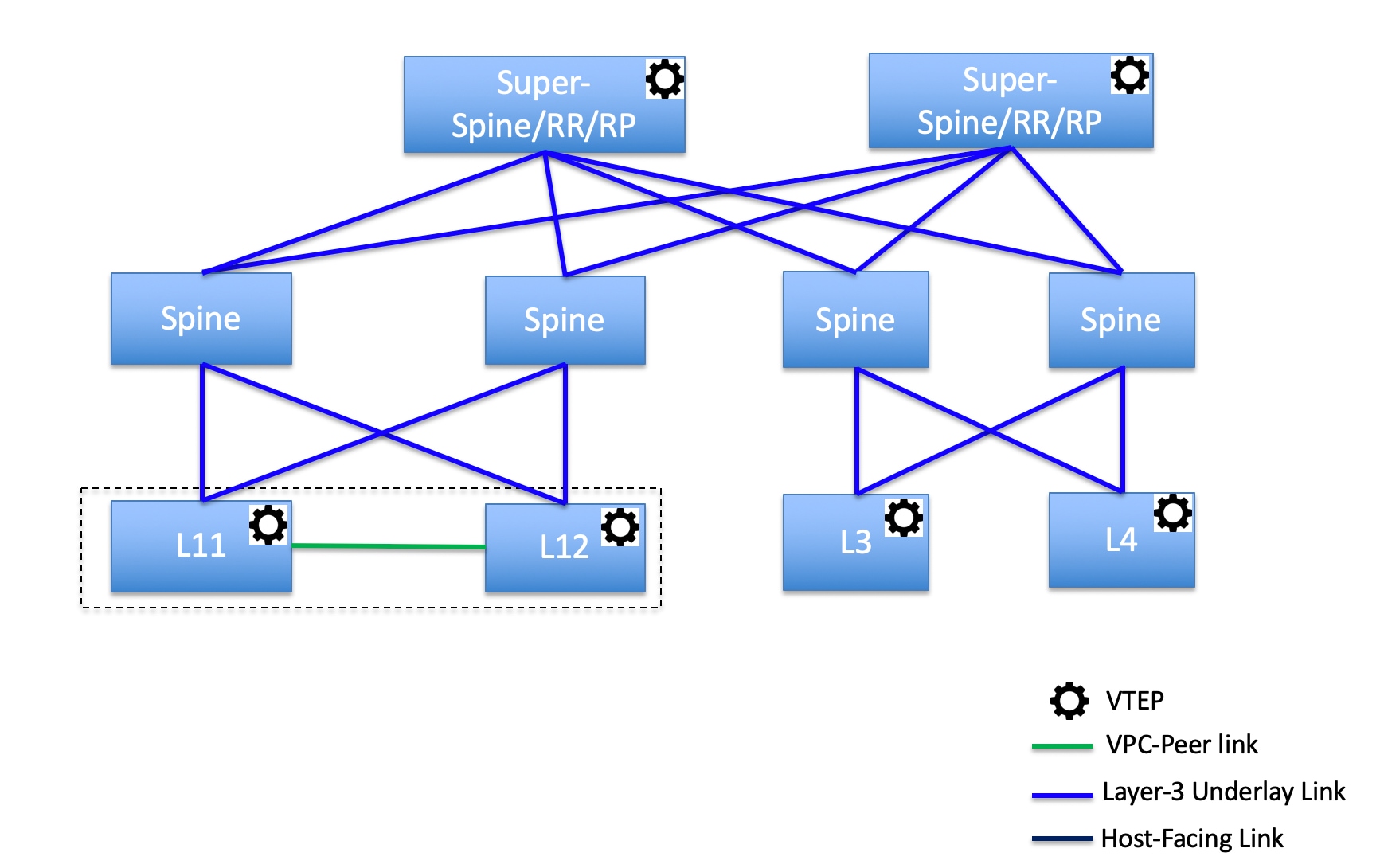
In this topology, leaf switches are connected to spines, and spines are connected to super spine switches which can be super spines, border super spines, and border gateway super spines.
Topology 2: Super Spine Switches Connected to Border
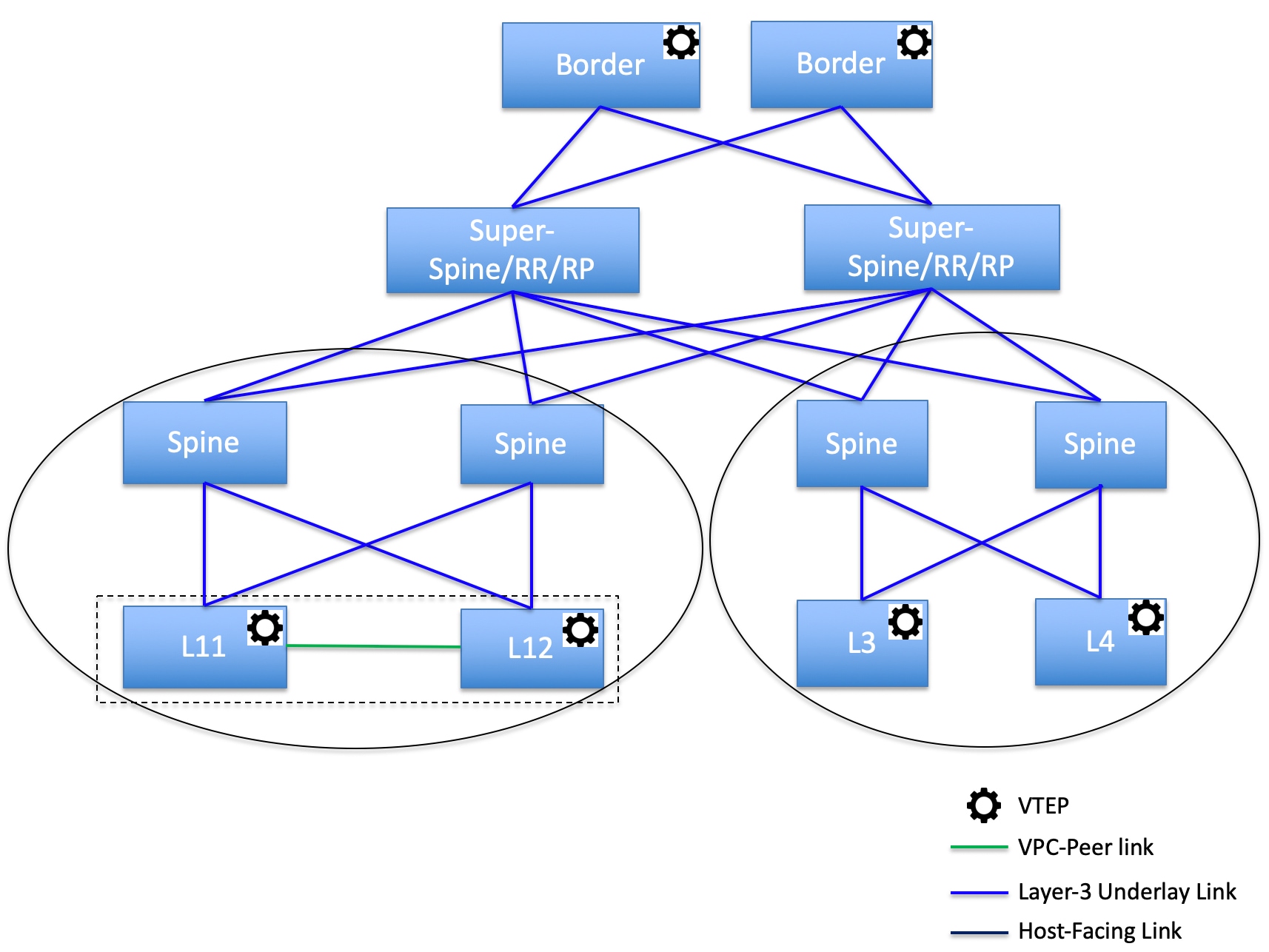
In this topology, there are four leaf switches connecting to the spine switches, which are connected to two super spine switches. These super spine switches are connected to the border or border gateway leaf switches.
Creating a vPC Setup
You can create a vPC setup for a pair of switches in the external fabric. Ensure that the switches are of the same role and connected to each other.
-
Right-click one of the two designated vPC switches and choose vPC Pairing.
The Select vPC peer dialog box comes up. It contains a list of potential peer switches. Ensure that the Recommended column for the vPC peer switch is updated as true.
Alternatively, you can also navigate to the Tabular view*from the *Actions pane. Choose a switch in the Switches tab and click vPC Pairing to create, edit, or unpair a vPC pair. However, you can use this option only when you choose a Cisco Nexus switch.
-
Click the radio button next to the vPC peer switch and choose vpc_pair from the vPC Pair Template drop-down list. Only templates with the VPC_PAIR template sub type are listed here.
The vPC Domain and vPC Peerlink tabs appear. You must fill up the fields in the tabs to create the vPC setup. The description for each field is displayed at the extreme right.
vPC Domain tab: Enter the vPC domain details.
vPC+: If the switch is part of a FabricPath vPC + setup, enable this check box and enter the FabricPath switch ID field.
Configure VTEPs: Check this check box to enter the source loopback IP addresses for the two vPC peer VTEPs and the loopback interface secondary IP address for NVE configuration.
NVE interface: Enter the NVE interface. vPC pairing will configure only the source loopback interface. Use the freeform interface manager for additional configuration.
NVE loopback configuration: Enter the IP address with the mask. vPC pairing will only configure primary and secondary IP address for loopback interface. Use the freeform interface manager for additional configuration.
vPC Peerlink tab: Enter the vPC peer-link details.
Switch Port Mode: Choose trunk or access or fabricpath.
If you select trunk, then corresponding fields (Trunk Allowed VLANs and Native VLAN) are enabled. If you select access, then the Access VLAN field is enabled. If you select fabricpath, then the trunk and access port related fields are disabled.
-
Click Save.
The vPC setup is created.
To update vPC setup details, do the following:
-
Right-click a vPC switch and choose vPC Pairing.
The vPC peer dialog box comes up.
-
Update the field(s) as needed.
When you update a field, the Unpair icon changes to Save.
-
Click Save to complete the update.
After creating a vPC pair, you can view vPC details in vPC Overview window.
-
Undeploying a vPC Setup
-
Right-click a vPC switch and choose vPC Pairing.
The vPC peer screen comes up.
-
Click Unpair at the bottom right part of the screen.
The vPC pair is deleted and the fabric topology window appears.
-
Click Deploy Config.
-
(Optional) Click the value under the Recalculate Config column.
View the pending configuration in the Config Preview dialog box. The following configuration details are deleted on the switch when you unpair: vPC feature, vPC domain, vPC peerlink, vPC peerlink member ports, loopback secondary IPs, and host vPCs. However, the host vPCs and port channels are not removed. Delete these port channels from the Interfaces window if required.
Resync the fabric if it is out of sync.
When you unpair, only PTIs are deleted for following features, but the configuration is not cleared on the switch during Deploy Config: NVE configuration, LACP feature, fabricpath feature, nv overlay feature, loopback primary ID. In case of host vPCs, port channels and their member ports are not cleared. You can delete these port channels from the Interfaces window if required. You can continue using these features on the switch even after unpairing.
If you are migrating from fabricpath to VXLAN, you need to clear the configuration on the device before deploying the VXLAN configuration.
More
Performing Actions on Switches
Change Mode
To change a mode for the switch, perform the following steps:
-
Navigate to Manage > Fabrics.
-
Click on a VXLAN EVPN fabric.
The fabric summary slide-in pane appears.
-
Click on the Launch icon.
The Fabric Overview page appears.
-
Click the Switches tab.
-
Click the check box for the switch you want to change modes for.
-
Choose Actions > More > Change Mode.
The Change Mode dialog box appears.
-
Click Maintenance from the drop-down list to change to maintenance mode or click Normal to change to normal mode.
-
Click Deploy Now to change the switch mode now or click Deploy Later to change the switch mode later.
Waiting for a Switch to Change Modes
You enable the Wait for switch mode change to maintenance on deploy option from the Fabric Overview > Switches page, the Actions drop-down list on the Manage > Inventory > Switches page, or by double-clicking on a fabric to access a switch on the Topology page. You can then right-click on the switch and click More > Change Mode to access the Change Mode dialog box.
Limitations of Waiting for a Switch to Change Modes
-
Support is provided for Cisco NX-OS devices only.
-
Support is not provided for Catalyst or Catalyst 9K switches. If you try to change the mode of a non-Cisco NX-OS device, you receive an error message.
-
You cannot change the mode of a switch using change control.
To enable waiting for a switch to change modes, perform the following steps:
-
Navigate to Manage > Fabrics.
-
Click on a VXLAN EVPN fabric.
The fabric summary slide-in pane appears.
-
Click on the Launch icon.
The Fabric Overview page appears.
-
Click the Switches tab.
-
Click the check box for the switch you want to change modes for.
-
Click Actions > More > Change Mode.
The Change Mode dialog box appears.
-
Click Maintenance from the drop-down list to change to maintenance mode or click Normal to change to normal mode.
-
Click the Wait for switch mode change to maintenance on deploy check box.
-
Click the Deploy Now button to change the switch mode.
Because you enabled the Wait for switch mode change to maintenance on deploy check box, the Deploy Later option is grayed out. NDFC retains the last action of the user for this check box.
It may take two to three minutes for the change-mode process to complete.
Provision RMA
To change mode for the switch, perform the following steps:
-
Click the check box for the required switch.
-
Click Actions > More > Provision RMA.
The Provision RMA page appears.
The Provision RMA page shows the replacement device 5-10 minutes after it is powered on.
Change Serial Number
You can change the serial number of switches. While pre-provisioning devices, you can provide dummy values for the serial number of the switch. After you configure the network successfully, you can change the serial number with the appropriate serial number of the switch.
Before changing the serial number of the switches, on the main window, click Actions > Recalculate and Deploy to save the latest data for the switch.
The change of serial number is supported only for Nexus 9000 Series switches. After you change a serial number with the actual serial number, we recommend to Re-POAP the device during the power-on bootstrap.
Copy Run Start
To copy the existing switch configuration to start the configuration, perform the following steps:
-
Click the check box for the required switch.
-
Click Actions > More > Copy Run Start.
The Copy Running Config to Startup Config page appears.
The Progress column shows the process in progress and the status description shows Deployment in progress.
A confirmation dialog box appears.
-
Click OK.
The status description column displays Deployment completed and the progress column displays in green.
-
Click Close to close this page.
Reload
-
To reload the required switch, click Actions > More > Reload.
A confirmation dialog box appears.
-
Click Confirm.
Restore Switch
You can restore a Cisco Nexus switch in external fabrics and LAN classic fabrics from the Cisco Nexus Dashboard Fabric Controller GUI. The information you restore at the switch level is extracted from the fabric-level backups. The switch level restore doesn’t restore fabric-level intents and other configurations applied using the fabric settings. Only switch-level intents are restored. Therefore, after you restore a switch, it might go out-of-sync because the fabric-level intents aren’t restored. Perform a fabric-level restore to restore the intents as well. You can restore only one switch at a time. You can’t restore a switch if the fabric where it’s discovered is part of an MSD fabric.
-
Click Actions > More > Reload.
The Restore Switch page appears and you are in the Select a Backup tab.
The Select a Backup tab displays the fabric backup details. It includes the following information:
Field
Description
Backup Date
Specifies the backup date and time.
Backup Version
Specifies the name of the backup.
Backup Tag
Specifies the version number of the switch.
NDFC Version
Specifies the NDFC version details.
Backup Type
Specifies the type of backup, either manual or automatic.
You can choose the automatic, manual, or golden backup. These backups are color-coded. Automatic backups are indicated in blue color.
Manual backups are indicated in midnight blue color. Golden backups are indicated in orange color. The automatic backups have only the versions in their names. Whereas the manual backups have tag names, which you gave when you initiated a manual backup, along with the version in the backup name. Hover over a backup to see the name.
You can now mark the backups that you don’t want to delete even after you reach the archiving limit. These backups are the golden backups. You can’t delete golden backups of fabrics. However, Cisco Nexus Dashboard Fabric Controller archives only up to 10 golden backups.
-
Click the radio button for the required backup to mark as golden.
-
Click Actions > Mark as golden.
A confirmation dialog box appears.
-
Click Confirm.
-
Click the radio button for backup to delete from the golden backup.
-
Click Actions > Remove as golden.
A confirmation dialog box appears.
-
Click Confirm.
Most of this information is at the fabric level, and may or may not directly impact the proceedings of the switch-level restore.
-
Click Next to move to the Restore Preview step.
You can view information about the switch name, switch serial, IP address, status, restore supported, delta configuration, and the VRF details.
-
(Optional) Click Get Config to preview the device configuration details.
The Config Preview dialog appears, which has the following three tabs.
Field
Description
Backup Config
This tab displays the backup configuration for the selected device.
Current Config
This tab displays the current running configuration of the selected device.
Side-by-side Comparison
This tab displays the current running configuration on the switch, and the backup configuration, which is the expected configuration.
-
Click Restore Intent to proceed to the Restore Status step in restoring.
The restore status and description appears for the switch.
-
Click Finish after the restore process is complete.
-
You can’t go back to the previous step because the fabric configurations change.
-
If the restore fails, the switch rolls back to the previous configuration.
Show Commands
You can use the following procedure tp view the commands in Nexus Dashboard Fabric Controller:
-
Choose Actions > More > Show commands.
The Switch Show Commands page appears.
-
Choose the required commands from the drop-down list and enter the required information in the text field.
-
Click Execute to view the CLI output and to clear the output.
-
Click Clear Output.
Exec Commands
The commands available in the EXEC mode include the show commands that display the device status and configuration information, the clear commands, and other commands that perform actions that you do not save in the device configuration.
The following procedure shows how to run EXEC commands in Nexus Dashboard Fabric Controller:
-
Choose Actions > More > Exec commands.
The Switch Show Commands page appears.
-
From the Template drop-down list, click exec_freeform or exec_elam_capture.
-
Enter the commands in the Freeform CLI for exec_freeform and the required IP addresses.
-
Click Deploy to run the EXEC commands.
-
On the CLI Execution Status page, you can check the status of the deployment.
-
Click Detailed Status under the Command column to view the details.
-
On the Command Execution Details page, click the information under the the CLI Response column to view the output or the response.
Delete Switches
You can delete one or more existing switches.
-
Click Actions > More > Delete switch(s).
A confirmation dialog box appears.
-
Click Confirm.
Enhanced Role-based Access Control
Starting from Cisco Nexus Dashboard Fabric Controller Release 12.0.1(a), all RBAC is in Nexus Dashboard. User-roles and access are defined from Nexus Dashboard for fabrics on NDFC.
The Nexus Dashboard admin role is considered as network-admin role in NDFC.
DCNM had five roles to perform various access and operations. If a user is access a fabric with network stage role has access to all other fabrics as a network stage role. Therefore, a username is restricted with their role in DCNM.
Cisco NDFC Release 12.0.1(a) has same five roles but you can do granular RBAC with integration of Nexus Dashboard. If a user accesses a fabric as a network stage role, the same user can access different fabric with other user role such as admin or operator role. Therefore, a user can have different access on the different fabrics in NDFC.
NDFC RBAC supports following roles:
-
NDFC Access Admin
-
NDFC Change Approver
-
NDFC Change Deployer
-
NDFC Device Upgrade Admin
-
NDFC Network Admin
-
NDFC Network Operator
-
NDFC Network Stager
The following roles are supported on DCNM for backward compatibility:
-
global-admin (mapped to network-admin)
-
server-admin (mapped to network-admin)
In any window, the actions that are restricted by the user role that is logged in are grayed out.
NDFC Access Admin
A user with the NDFC Access Admin role can perform operations only in the Interface Manager window for all fabrics that they have access to.
An NDFC access admin can perform the following actions:
-
Add, edit, delete and deploy layer 2 port channels, and vPC.
-
Edit host vPC, and ethernet interfaces.
-
Save, preview, and deploy from management interfaces.
-
Edit interfaces for LAN classic, and IPFM fabrics.
Apart from nve, management, tunnel, subinterface, SVI, interface grouping, and loopback interfaces
However, a user with the Cisco Nexus Dashboard Fabric Controller access admin role cannot perform the following actions:
-
Cannot edit layer 3 port channels, ST FEX, AA FEX, loopback interfaces, nve interfaces, and subinterfaces.
-
Cannot edit member interfaces and port channels of Layer 3, ST FEX, AA FEX.
-
Cannot edit interfaces with policy associated from underlay and link for easy fabrics.
-
Cannot edit peer link port channel.
-
Cannot edit management interface.
-
Cannot edit tunnel.
The icons and buttons are grayed out for this role when the fabric or Cisco Nexus Dashboard Fabric Controller is in deployment-freeze mode.
NDFC Change Approver
The NDFC Change Approver role became available as part of the change control and rollback features, introduced in NDFC release 12.1.3. See Change Control and Rollback for more information.
Users with the NDFC Change Approver privilege can approve change control tickets.
A user that is assigned with the NDFC Change Approver role can double-check changes that are associated with a specific ticket and approve or deny those changes.
NDFC Change Deployer
The NDFC Change Deployer role became available as part of the change control and rollback features, introduced in NDFC release 12.1.3. See Change Control and Rollback for more information.
Users with the NDFC Change Deployer privilege can deploy change control tickets.
Once a change control ticket is approved by a user with the NDFC Change Approver role, that ticket is then available to any user that is assigned with the NDFC Change Deployer role, who can then deploy the changes that have moved to the deployment stage in the change control workflow.
NDFC Device Upgrade Admin
A user with the NDFC Device Upgrade Admin role can perform operations only in Fabric Software window.
See Fabric Software for more information.
NDFC Network Admin
A user with the NDFC Network Admin role can perform all the operations in Cisco Nexus Dashboard Fabric Controller.
From Cisco Nexus Dashboard Fabric Controller Release 12.1.1e, a user with this role can perform all operations for MSD fabrics in Networks and VRFs.
You can freeze a particular fabric or all fabrics in Cisco Nexus Dashboard Fabric Controller if you are a user with the NDFC Network Admin role.
Make sure that the switch user role for discovery or add switches or LAN credentials for NDFC must have the network-admin role.
NDFC Network Operator
A network operator can view fabric builder, fabric settings, preview configurations, policies, and templates. However, a network operator cannot perform the following actions:
-
Cannot change expected configurations of any switch within any fabric.
-
Cannot deploy any configurations to switches.
-
Cannot access the administration options like licensing, creating more users, and so on.
The difference between a network operator and a network stager is that, as a network stager you can only define intent for existing fabrics, but cannot deploy those configurations.
Only a network admin can deploy the changes and edits that are staged by a user with the network stager role.
NDFC Network Stager
A user with the NDFC Network Stager role can make configuration changes on Cisco Nexus Dashboard Fabric Controller. A user with the NDFC Network Admin role can deploy these changes later. A network stager can perform the following actions:
-
Edit interface configurations
-
View or edit policies
-
Create interfaces
-
Change fabric settings
-
Edit or create templates
However, a network stager cannot perform the following actions:
-
Cannot make any configuration deployments to switches.
-
Cannot perform deployment-related actions from the Cisco Nexus Dashboard Fabric Controller Web UI or the REST APIs.
-
Cannot access the administration options like licensing, creating more users, and so on.
-
Cannot move switches in and out of maintenance mode.
-
Cannot move fabrics in and out of deployment-freeze mode.
-
Cannot install patches.
-
Cannot upgrade switches.
-
Cannot create or delete fabrics.
-
Cannot import or delete switches.
Choosing Default Authentication Domain
By default, the login screen on Nexus Dashboard chooses the local domain for authentication. You can change domain at login time by choosing available domains from drop-down list.
Nexus Dashboard supports local and remote authentication. The remote authentication providers for Nexus Dashboard include RADIUS, and TACACS. For more information on authentication support, see https://www.cisco.com/c/en/us/td/docs/dcn/nd/2x/user-guide/cisco-nexus-dashboard-user-guide-211.pdf.
The following table describes RBAC comparison between DCNM and NDFC access:
| DCNM 11.5(x) | NDFC 12.0.x and 12.1.x |
|---|---|
|
|
|
A single role is associated with the user by disabling or restricting the access to options in DCNM. |
A single role displays only privileged resources on the selected page and restricted access are grayed out based on security domain associated with selected resource on further options on NDFC. |
|
DCNM AV Pair format with shells, roles, and optional access constraints. |
Nexus Dashboard AV Pair format with shells, domains. |
|
Supported roles based on deployment type LAN, SAN, or PMN. |
Supported roles such as network-admin, network-operator, device-upg-admin, network-stager, access-admin are in NDFC. Support for legacy roles for backward compatibility. Nexus Dashboard admin role as network-admin of DCNM. |
The following table describes DCNM 11.5(x) AV Pair format:
| Cisco DCNM Role | RADIUS Cisco-AV-Pair Value | TACACS+ Shell Cisco-AV-Pair Value |
|---|---|---|
|
Network Operator |
shell:roles = "network-operator" dcnm-access="group1 group2 group5" |
cisco-av-pair=shell:roles="network-operator" dcnm-access="group1 group2 group5" |
|
Network Admin |
shell:roles = "network-admin" dcnm-access="group1group2 group5" |
cisco-av-pair=shell:roles="network-admin" dcnm-access="group1 group2 group5" |
The following table describes NDFC 12.x AV Pair format:
| User Role | AVPair Value |
|---|---|
|
NDFC Access Admin |
access-admin |
|
NDFC Device Upgrade Admin |
device-upg-admin |
|
NDFC Network Admin |
network-admin |
|
NDFC Network Operator |
network-operator |
|
NDFC Network Stager |
network-stager |
The AV pair string format differs when configuring a read/write role, read-only role, or a combination of read/write and read-only roles for a specific user. A typical string includes the domain, followed by the read-write roles separated from the read-only roles using the slash (/) character; individual roles are separated by the pipe (|) character:
shell:domains=<domain>/<writeRole1>|<writeRole2>/<readRole1>|<readRole2>
Enhanced RBAC Use-Cases
There are various fabrics in NDFC. By default a user is an admin for all the fabrics. For an example, a username Cisco can have admin role access to a Fabric-A and stager role access to another Fabric-B.
On Nexus Dashboard, all security policies are part of security domains. You can create the user and give access to these security domains.
To create a user and define specific roles, perform the following steps:
-
To create user in security domains:
-
Log in to Nexus Dashboard with admin role and navigate to Administrative tab.
-
On Security Domain tab, click Create Security Domain and create the following security domains:
-
all - Similar to network-admin role. This domain has administrative access to Nexus Dashboard and NDFC service application.
-
cisco-admin - full network-admin access to Fabric-A
-
cisco-stager - network-stager only access to Fabric-B
-
-
-
To create a local user Cisco.
-
Navigate to Users > Local.
-
On Local tab, click Create Local User.
The Create Local User window appears.
-
Enter Cisco in User ID text field, provide appropriate passwords in respective fields.
-
After you create a Cisco user, navigate to Local window, click on elipses icon in Cisco username row and then click Edit User.
The Edit User window appears.
-
-
On Edit User window, by default, all security domain exists. Click Add Security Domain and Roles to add other security domains.
The Add Security Domain and Roles window appears.
-
Choose cisco-admin domain from option drop-down list and choose NDFC Access Admin check box and then click Save.
-
Repeat step a to add cisco-stager domain for NDFC Network Stager role.
-
To associate security domains to respective fabric sites, do the following:
On Nexus Dashboard, navigate to Sites window. Click on Fabric-A site name.
A slide-in pane appears. You can view all security domain for the Fabric-A site.
-
To add the Cisco user as network-admin for Fabric-A, click Elipse icon and Edit Site.
-
Delete all security domain and add network-admin domain and save the changes.
Similarly you can add for network-stager domain.
-
Log out from Nexus Dashboard and log in back as Cisco user.
The user role Cisco can view only NDFC related options on Nexus Dashboard based on the permissions. The user access restricted to Nexus Dashboard services.
-
Navigate to NDFC application.
The user Cisco can perform operations on two sites on NDFC, as the user is assigned as network-admin role for Fabric-A and network-stager role for Fabric-B.
Network-admin role can create an interface for Fabric-A and deploy it. Whereas network-stager role can create an interface for Fabric-B, but access is restricted to deploy.
-
Nexus Dashboard Security Domains
Access control information about a user login contains authentication data like user ID, password, and so on. Based on the authorization data, you can access resources accordingly. Admins in Cisco Nexus Dashboard can create security domains and group various resource types, resource instance, and map them into a security domain. The admins define an AV-pair for each user, which defines the access privileges for users to different resources in Cisco Nexus Dashboard. When you create a fabric, a site is created in Nexus Dashboard with the same fabric name. You can create and view these sites from Nexus Dashboard > Sites.
The Cisco Nexus Dashboard Fabric Controller REST APIs use this information to perform any action by checking the authorization.
When accessing REST APIs, you can verify passed payload in JSON format. Ensure that the payload is an appropriate JSON format.
When you upgrade from Cisco Nexus Dashboard Fabric Controller Release 11.x, each fabric is mapped to an autogenerated site of the same name. All these sites are mapped into the all security domain in Nexus Dashboard.
All resources are placed in all domain before they are assigned or mapped to other domains. The all security domain does not include all the available security domains in Nexus Dashboard.
AV-Pairs
A group of security domains along with read and write roles for each domain are specified using AV-pairs. Administrators define AV-pair for each user. The AV-pair defines the access privileges to users across various resources in Nexus Dashboard.
The AV-pair format is as follows:
"avpair":

"shell:domains=security-domain/write-role-1|write-role-2,security-domain/write-role-1|write-role2/read-role-1|read-role-2"``
For example:
"avpair":

"shell:domains=all/network-admin/app-user|network-operator"
This example makes the user a super-user. It’s best to avoid examples with "all/admin/".
The write role is inclusive of read role as well. Hence, all/network-admin/ and all/network-admin/network-admin are the same.
From Cisco Nexus Dashboard Fabric Controller Release 12.0.1a supports the existing AV-pair format that you created in Cisco Nexus Dashboard Fabric Controller Release 11.x. However, if you are creating a new AV-pair, use the format that is mentioned above. Ensure that the shell: domains must not have any spaces.
Specifying Cisco NX-OS User Roles and SNMPv3 Parameters on AAA Servers
You can use the VSA cisco-AV-pair on AAA servers to specify user role mapping for the Cisco NX-OS device using this format:
shell:roles="roleA roleB ..."If you do not specify the role option in the cisco-AV-pair attribute, the default user role is network-operator.
You can also specify your SNMPv3 authentication and Privacy protocol attributes as follows:
shell:roles="roleA roleB..." snmpv3:auth=SHA priv=AES-128The SNMPv3 authentication protocol options are SHA and MD5. The Privacy protocol options are AES-128 and DES. If you do not specify these options in the cisco-AV-pair attribute, MD5 and DES are the default authentication protocols.
Creating a Security Domain
To create a security domain from Cisco Nexus Dashboard, perform the following steps:
-
Log into Cisco Nexus Dashboard.
-
Choose Administrative > Security.
-
Navigate to Security Domains tab.
-
Click Create Security Domain.
-
Enter the required details and click Create.
Creating a User
To create a user from Cisco Nexus Dashboard, perform the following steps:
-
Log into Cisco Nexus Dashboard.
-
Choose Administrative > Users.
-
Click Create Local User.
-
Enter the required details and click Add Security Domain.
-
Choose a domain from the drop-down list.
-
Assign a Cisco Nexus Dashboard Fabric Controller service read or write role by checking the appropriate check box.
-
Click Save.
Copyright
THE SPECIFICATIONS AND INFORMATION REGARDING THE PRODUCTS IN THIS MANUAL ARE SUBJECT TO CHANGE WITHOUT NOTICE. ALL STATEMENTS, INFORMATION, AND RECOMMENDATIONS IN THIS MANUAL ARE BELIEVED TO BE ACCURATE BUT ARE PRESENTED WITHOUT WARRANTY OF ANY KIND, EXPRESS OR IMPLIED. USERS MUST TAKE FULL RESPONSIBILITY FOR THEIR APPLICATION OF ANY PRODUCTS.
THE SOFTWARE LICENSE AND LIMITED WARRANTY FOR THE ACCOMPANYING PRODUCT ARE SET FORTH IN THE INFORMATION PACKET THAT SHIPPED WITH THE PRODUCT AND ARE INCORPORATED HEREIN BY THIS REFERENCE. IF YOU ARE UNABLE TO LOCATE THE SOFTWARE LICENSE OR LIMITED WARRANTY, CONTACT YOUR CISCO REPRESENTATIVE FOR A COPY.
The Cisco implementation of TCP header compression is an adaptation of a program developed by the University of California, Berkeley (UCB) as part of UCB’s public domain version of the UNIX operating system. All rights reserved. Copyright © 1981, Regents of the University of California.
NOTWITHSTANDING ANY OTHER WARRANTY HEREIN, ALL DOCUMENT FILES AND SOFTWARE OF THESE SUPPLIERS ARE PROVIDED “AS IS" WITH ALL FAULTS. CISCO AND THE ABOVE-NAMED SUPPLIERS DISCLAIM ALL WARRANTIES, EXPRESSED OR IMPLIED, INCLUDING, WITHOUT LIMITATION, THOSE OF MERCHANTABILITY, FITNESS FOR A PARTICULAR PURPOSE AND NONINFRINGEMENT OR ARISING FROM A COURSE OF DEALING, USAGE, OR TRADE PRACTICE.
IN NO EVENT SHALL CISCO OR ITS SUPPLIERS BE LIABLE FOR ANY INDIRECT, SPECIAL, CONSEQUENTIAL, OR INCIDENTAL DAMAGES, INCLUDING, WITHOUT LIMITATION, LOST PROFITS OR LOSS OR DAMAGE TO DATA ARISING OUT OF THE USE OR INABILITY TO USE THIS MANUAL, EVEN IF CISCO OR ITS SUPPLIERS HAVE BEEN ADVISED OF THE POSSIBILITY OF SUCH DAMAGES.
Any Internet Protocol (IP) addresses and phone numbers used in this document are not intended to be actual addresses and phone numbers. Any examples, command display output, network topology diagrams, and other figures included in the document are shown for illustrative purposes only. Any use of actual IP addresses or phone numbers in illustrative content is unintentional and coincidental.
The documentation set for this product strives to use bias-free language. For the purposes of this documentation set, bias-free is defined as language that does not imply discrimination based on age, disability, gender, racial identity, ethnic identity, sexual orientation, socioeconomic status, and intersectionality. Exceptions may be present in the documentation due to language that is hardcoded in the user interfaces of the product software, language used based on RFP documentation, or language that is used by a referenced third-party product.
Cisco and the Cisco logo are trademarks or registered trademarks of Cisco and/or its affiliates in the U.S. and other countries. To view a list of Cisco trademarks, go to this URL: https://www.cisco.com/go/trademarks. Third-party trademarks mentioned are the property of their respective owners. The use of the word partner does not imply a partnership relationship between Cisco and any other company. (1110R)
© 2017-2024 Cisco Systems, Inc. All rights reserved.