Create a Layer 2 Network
Procedure
|
Step 1 |
In NDFC, navigate to , if you are not there already. A page showing all of the configured fabrics appears. |
|
Step 2 |
Double-click the Enhanced Classic LAN fabric that you created using the procedures provided in Configure the Enhanced Classic LAN Fabric. The Fabric Overview page for that fabric appears. |
|
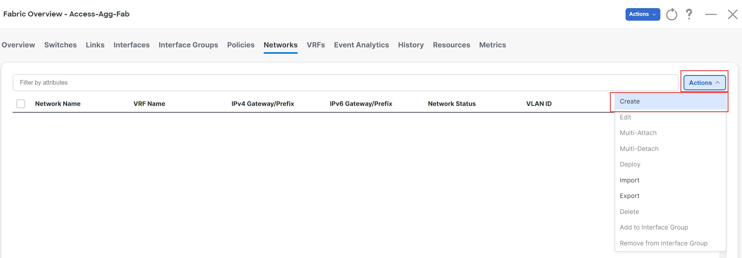
Step 3 |
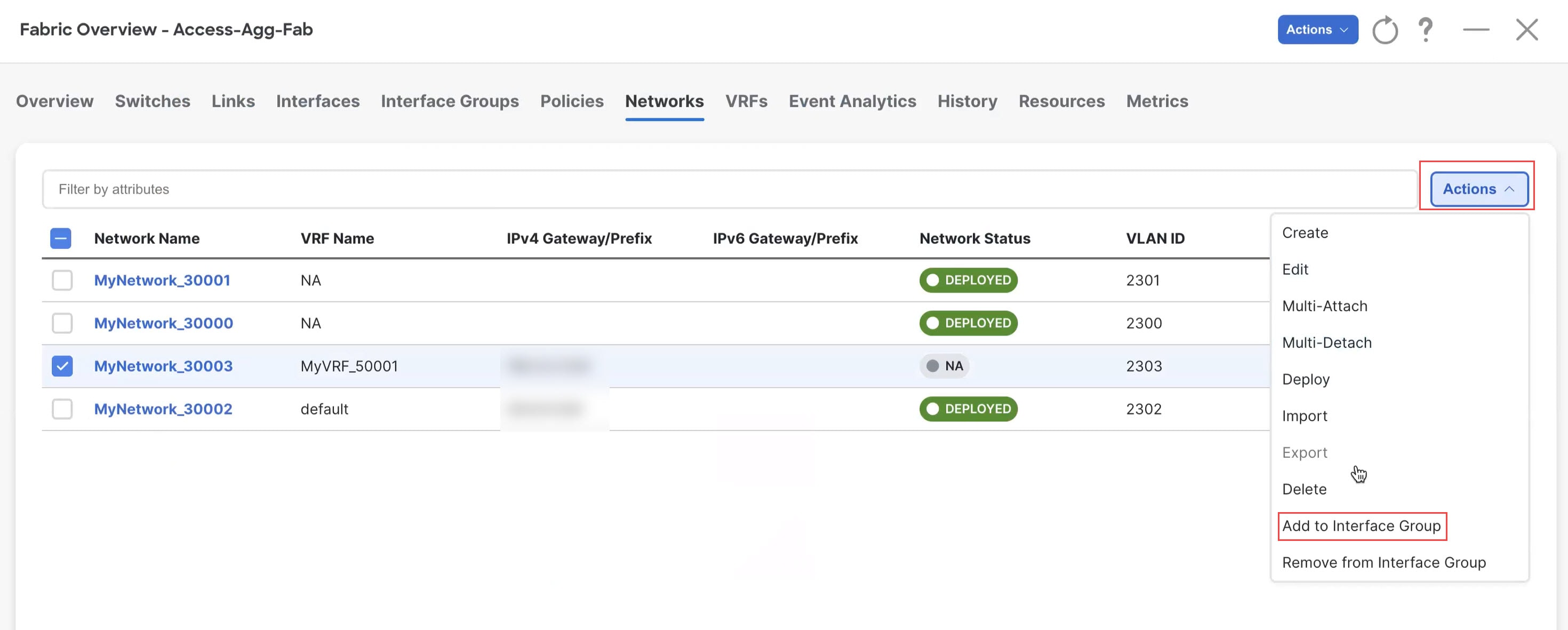
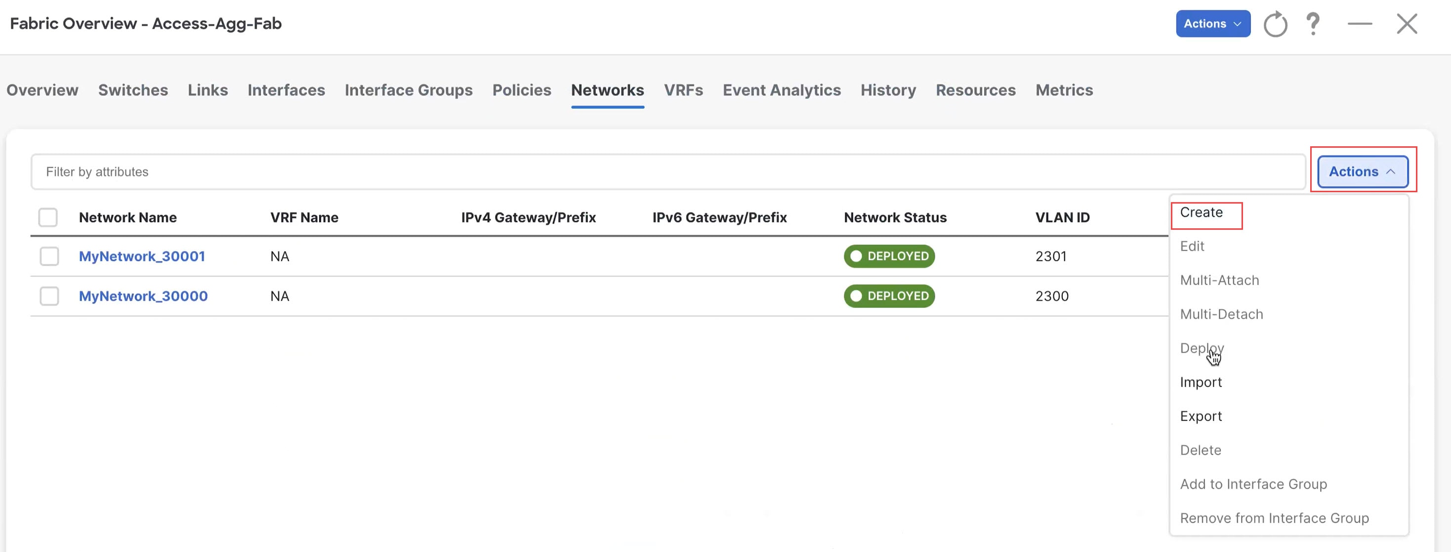
Click the Networks tab. |
|
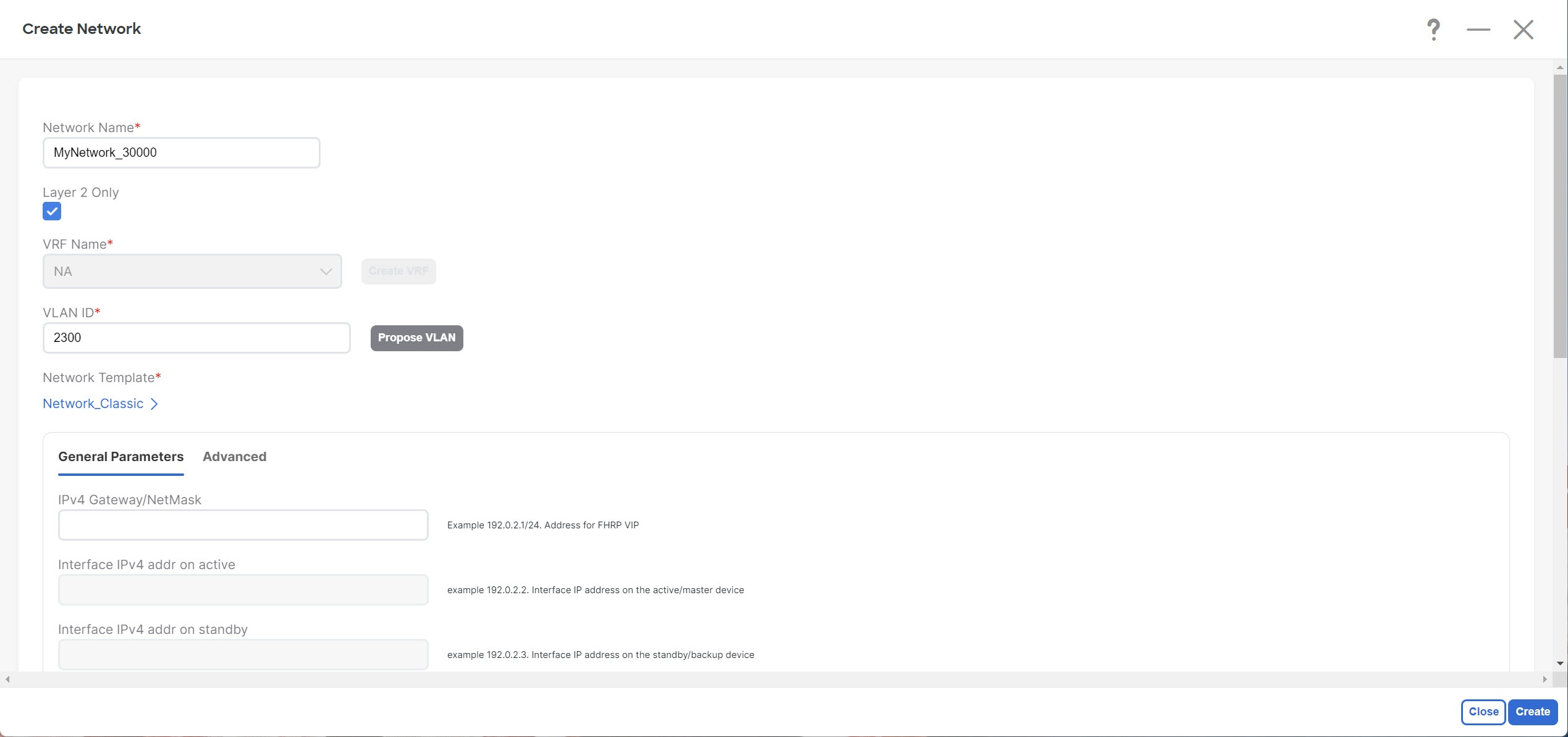
Step 4 |
Create the Layer 2 network.
|
|
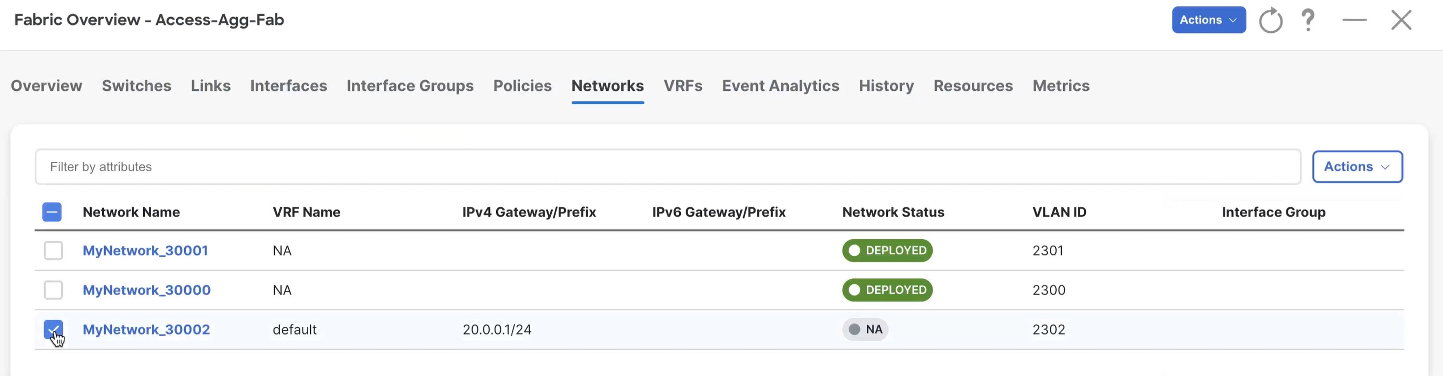
Step 5 |
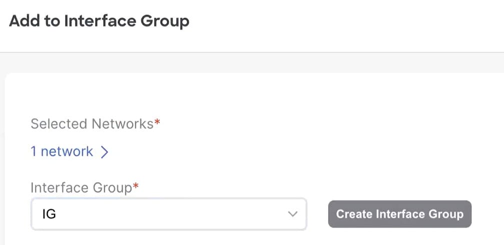
Add the network to an interface group, if necessary. Interface groups are useful if you are trying to deploy a network to a group of interfaces.
|
|
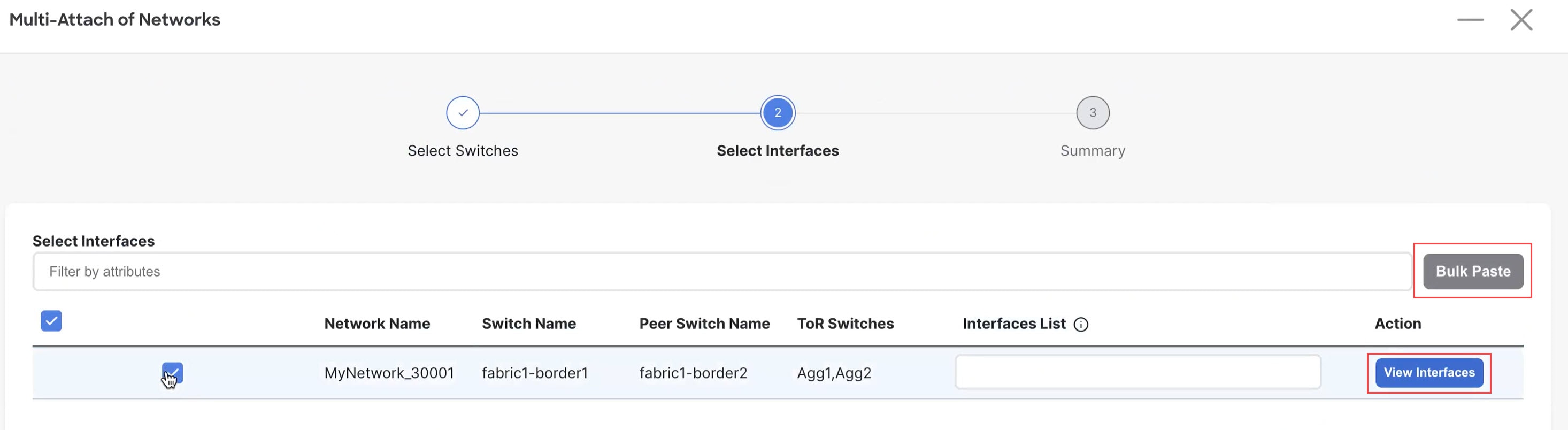
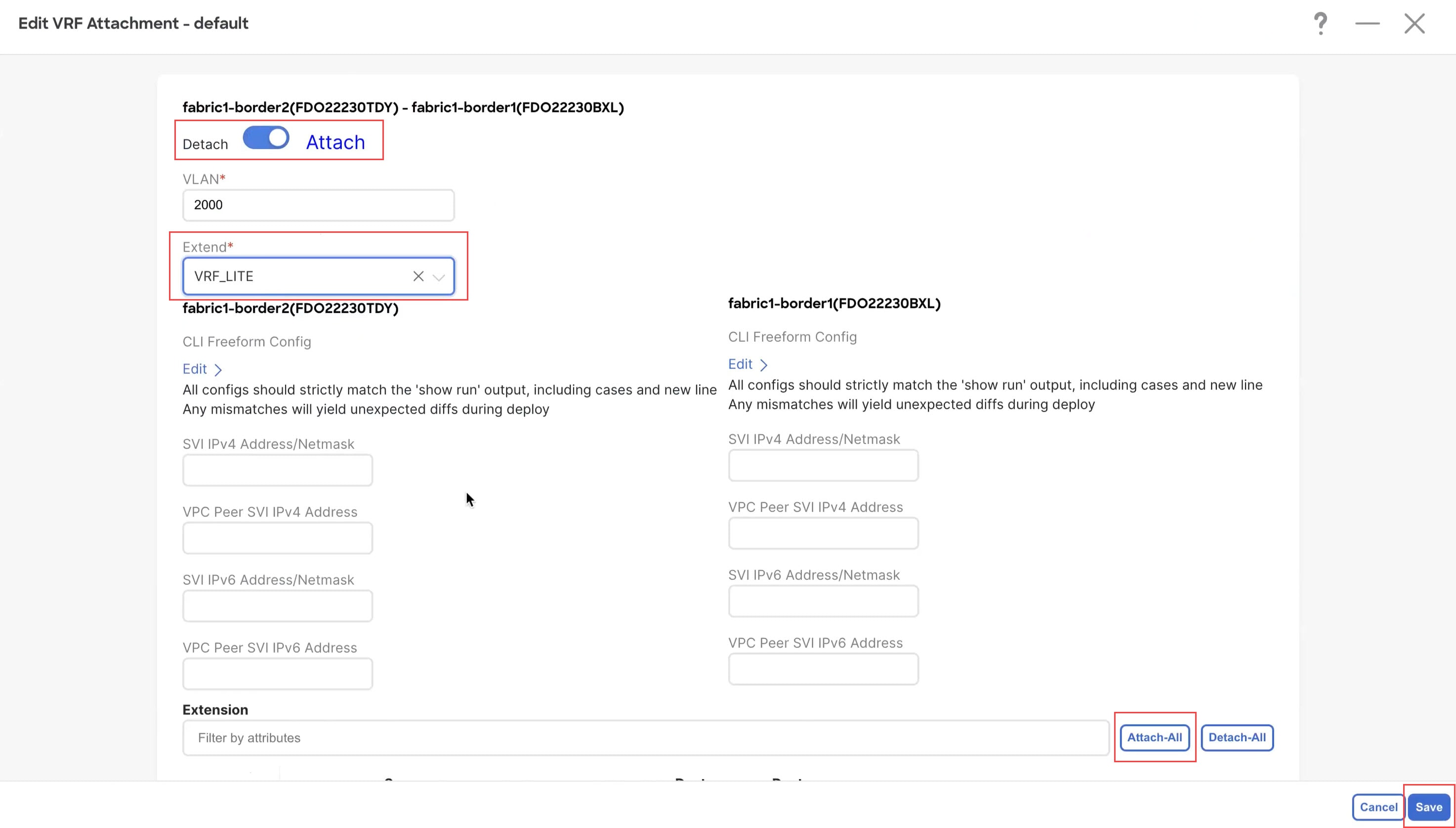
Step 6 |
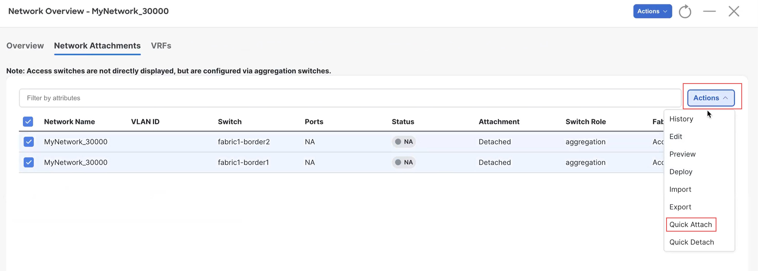
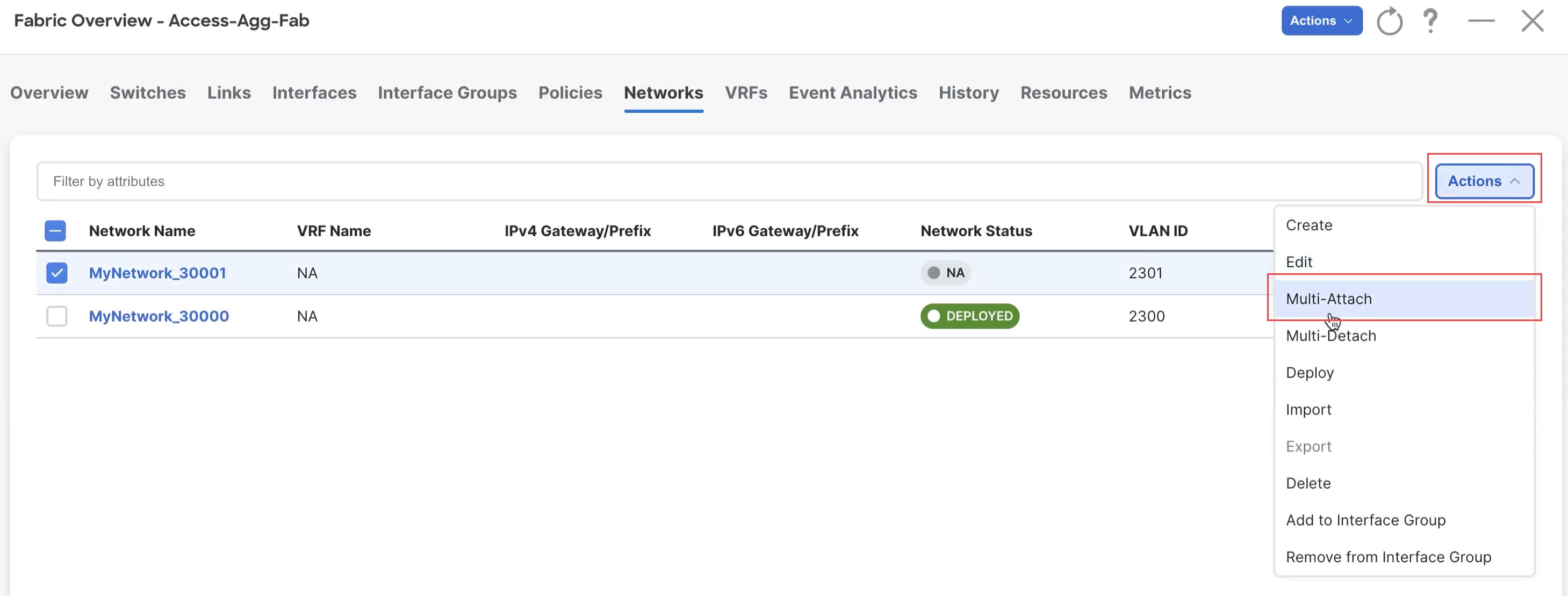
Attach the network. Once you've created the Layer 2 network, you can attach it to host-facing ports on the Access switch, which will then allow the VLAN on these trunk or access ports and also on the vPC/port channel/standalone ports between the Access and Aggregation switches. Determine if you want to perform a quick attach or a multi-attach.
|
|
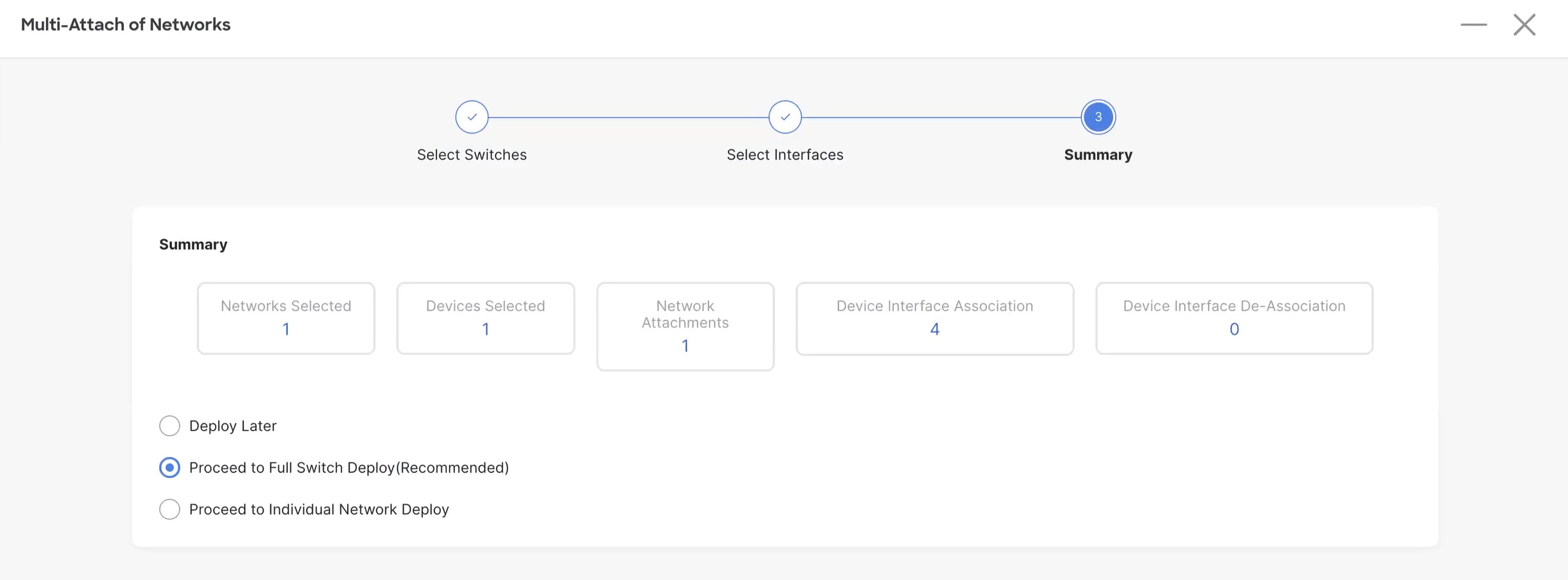
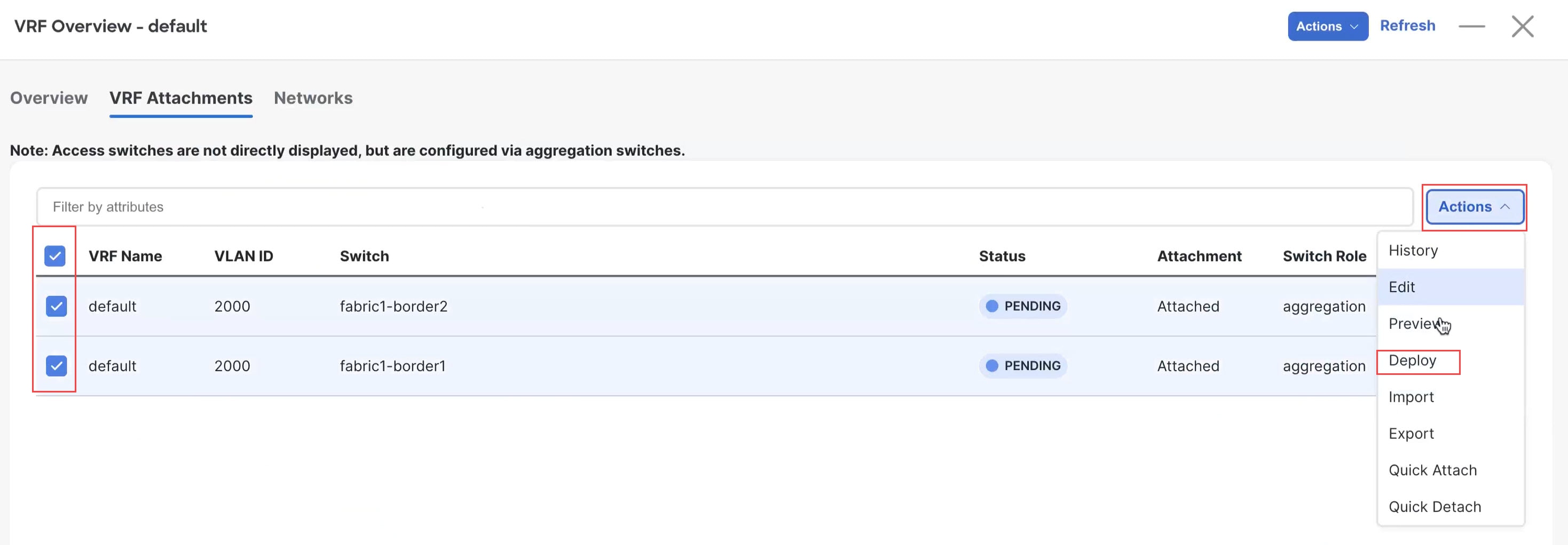
Step 7 |
Deploy the network. In the Network Attachments window, select the networks that you just attached, then click . 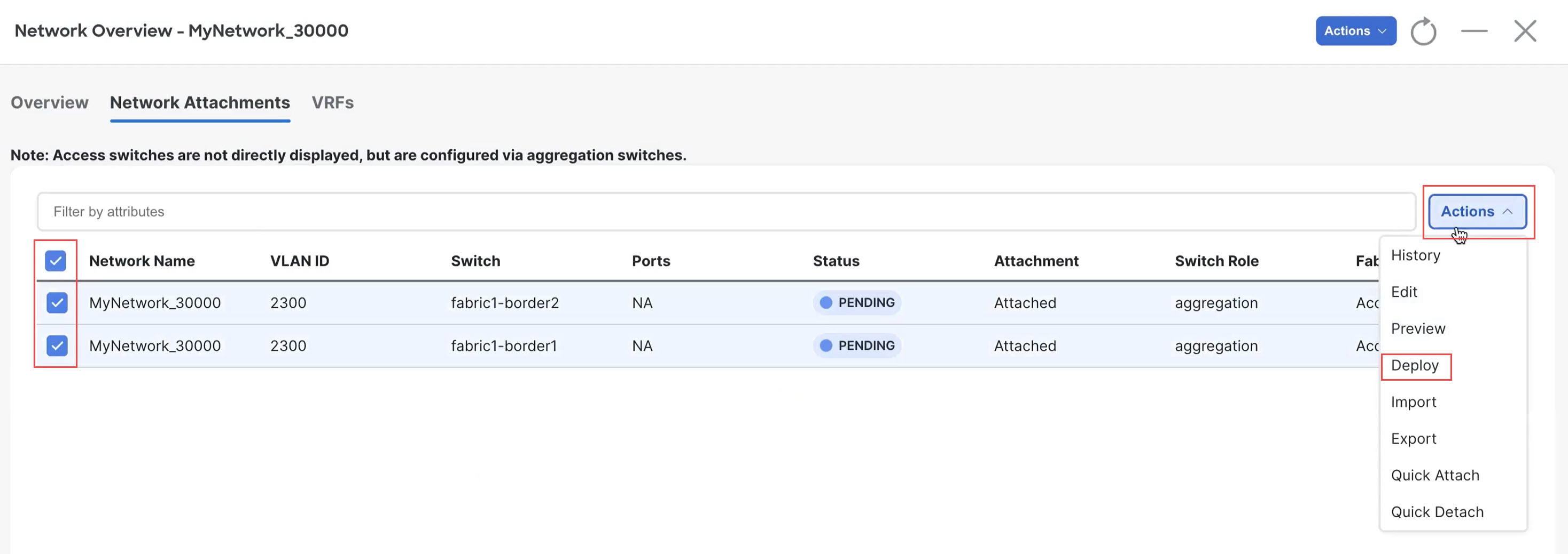
|
|
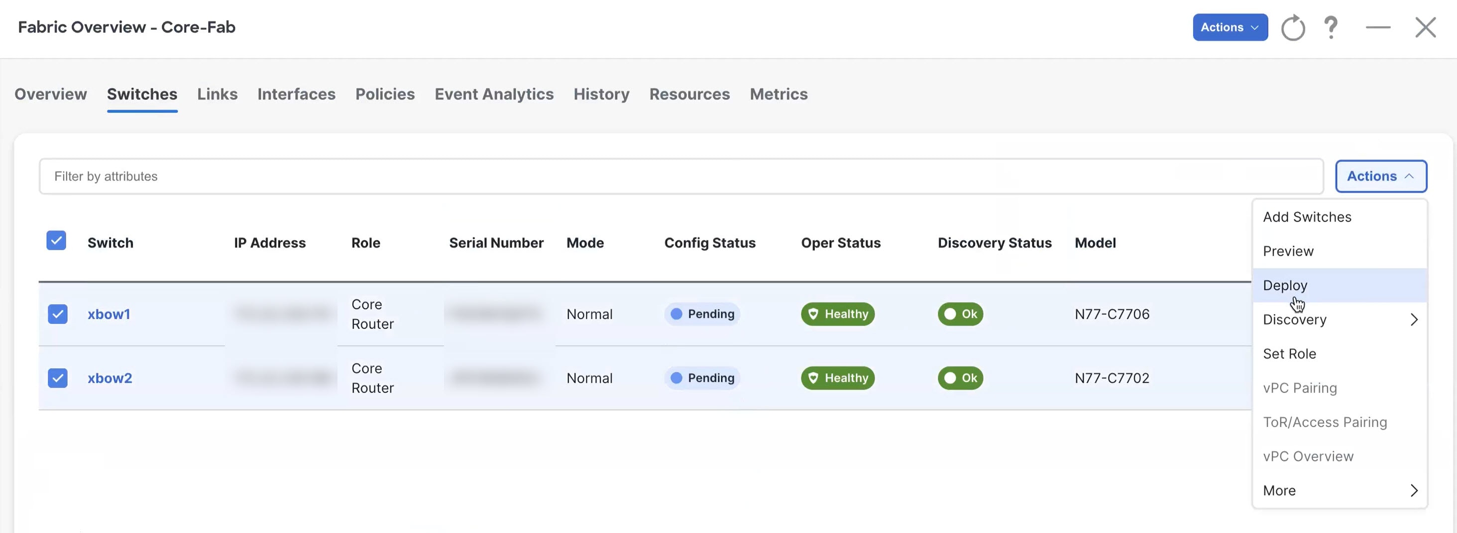
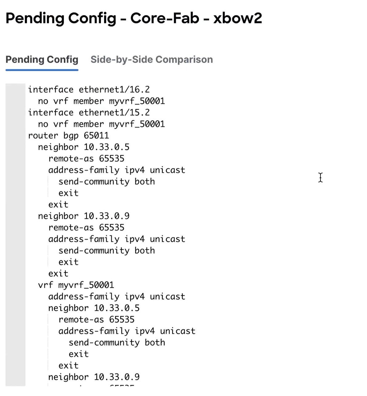
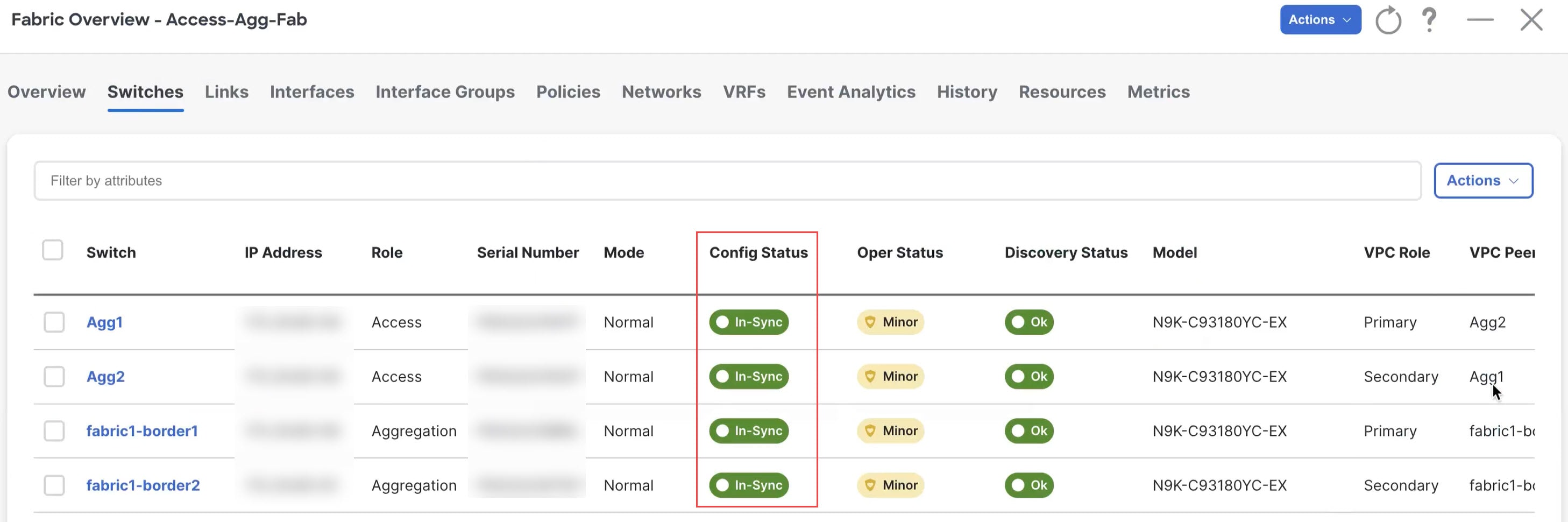
Step 8 |
When the recalculation process is completed, click Deploy and verify that the status shown in the Config Status column shows as In-Sync. 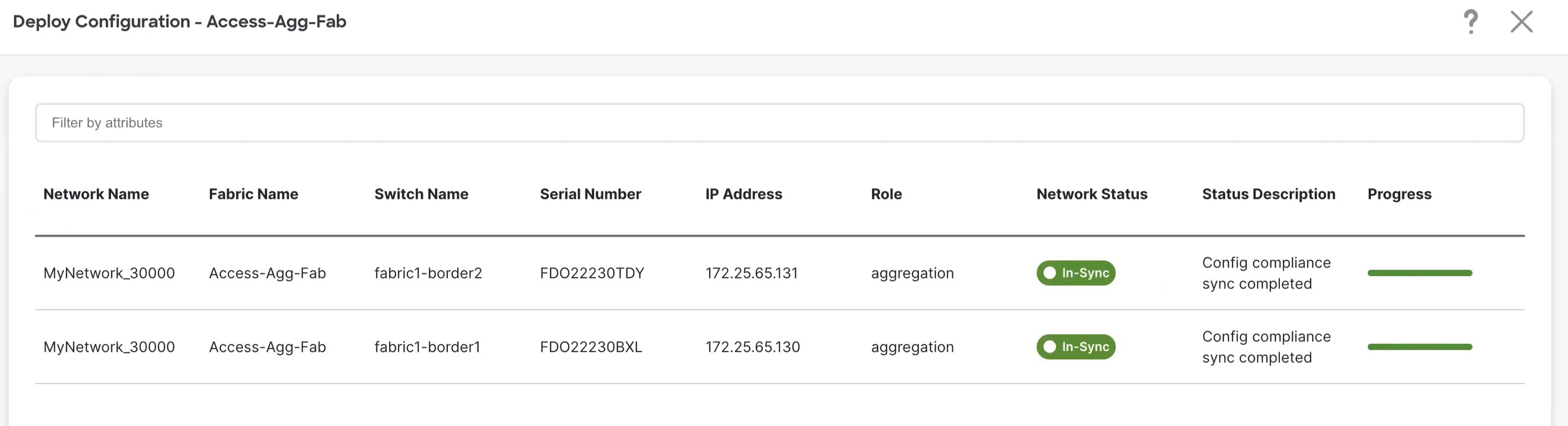
|
What to do next
Create a Layer 3 network using the procedures provided in Create a Layer 3 Network.
 Feedback