Configure the Enhanced Classic LAN Fabric
In these procedures, you will be configuring the Enhanced Classic LAN fabric that will be used to manage part of your legacy/classic network through NDFC.
-
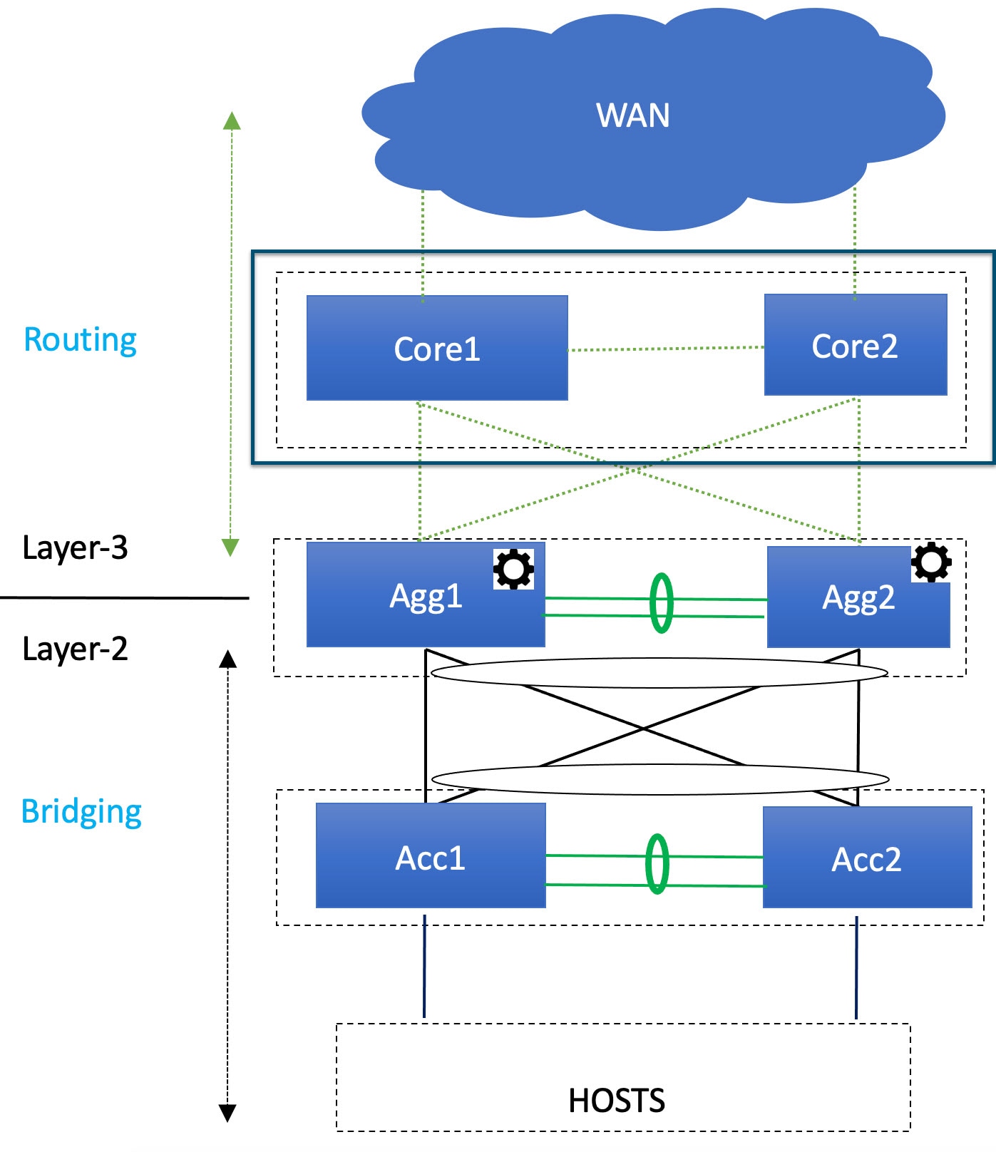
If your existing legacy/classic network falls into the three-tier topology scenario, you will be configuring a fabric that will be used for the Access and Aggregation tiers in that three-tier topology.
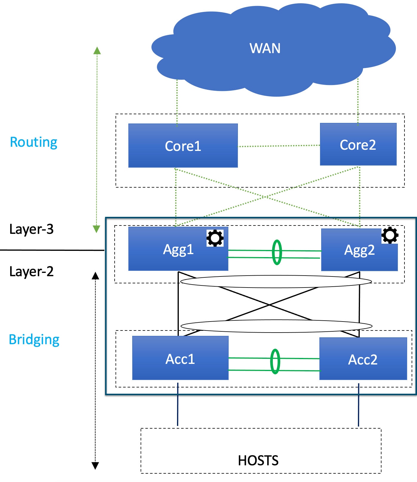
You will be configuring a separate External Connectivity Network fabric for the Core tier in a later section in this case.
-
If your existing legacy/classic network falls into the two-tier (Collapsed Core) topology scenario, you will be configuring a fabric that will be used for both tiers in that two-tier topology.
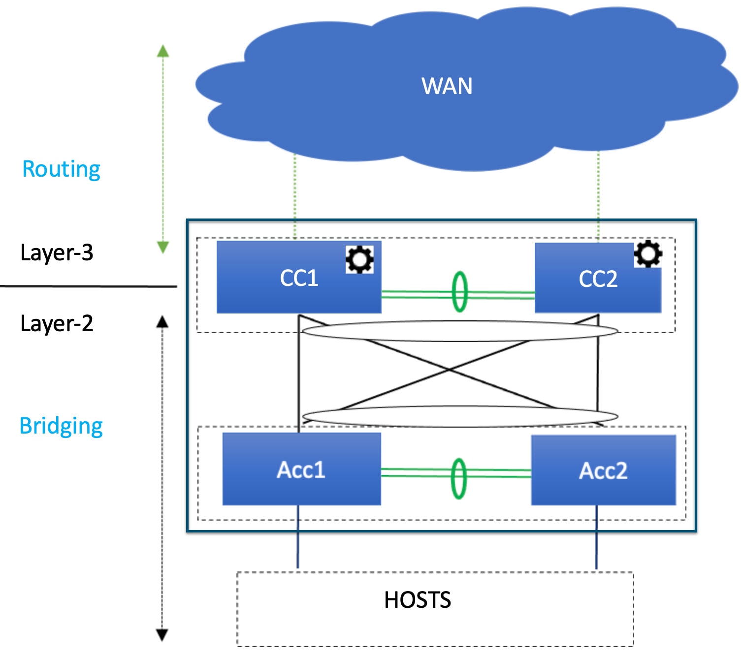
In this case, the Core and Aggregation tiers are collapsed into a single, combined tier called the "Collapsed Core" tier.
You will be using the Enhanced Classic LAN fabric template for these configurations. For more information on that fabric template, see Enhanced Classic LAN.
Before you begin
Verify that you have completed all of the necessary tasks provided in Prerequisites before beginning these procedures.
Procedure
|
Step 1 |
In NDFC, navigate to . A page showing all of the configured fabrics appears. |
||
|
Step 2 |
Click . 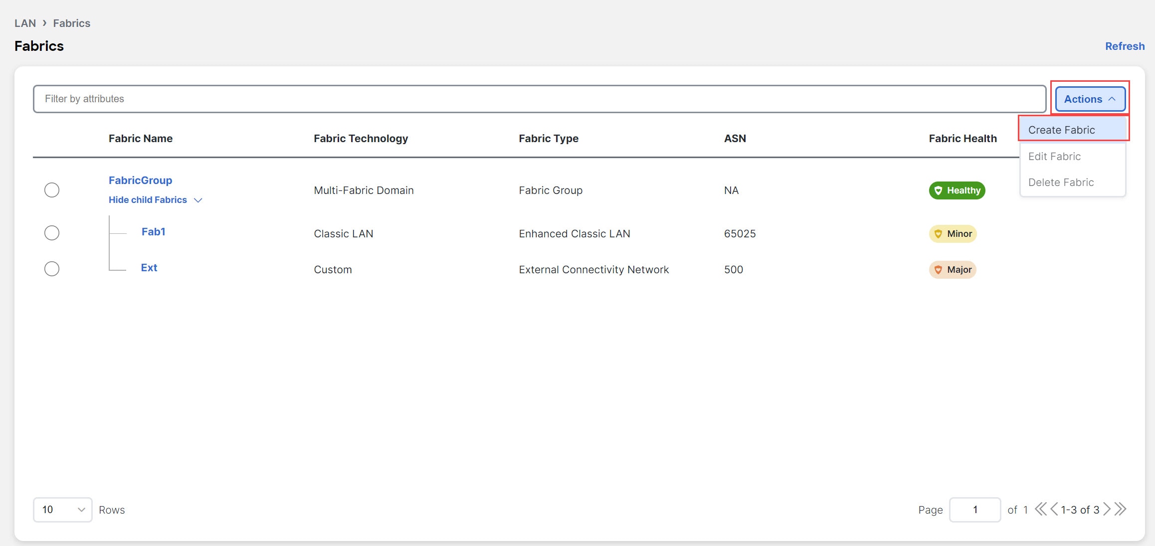
|
||
|
Step 3 |
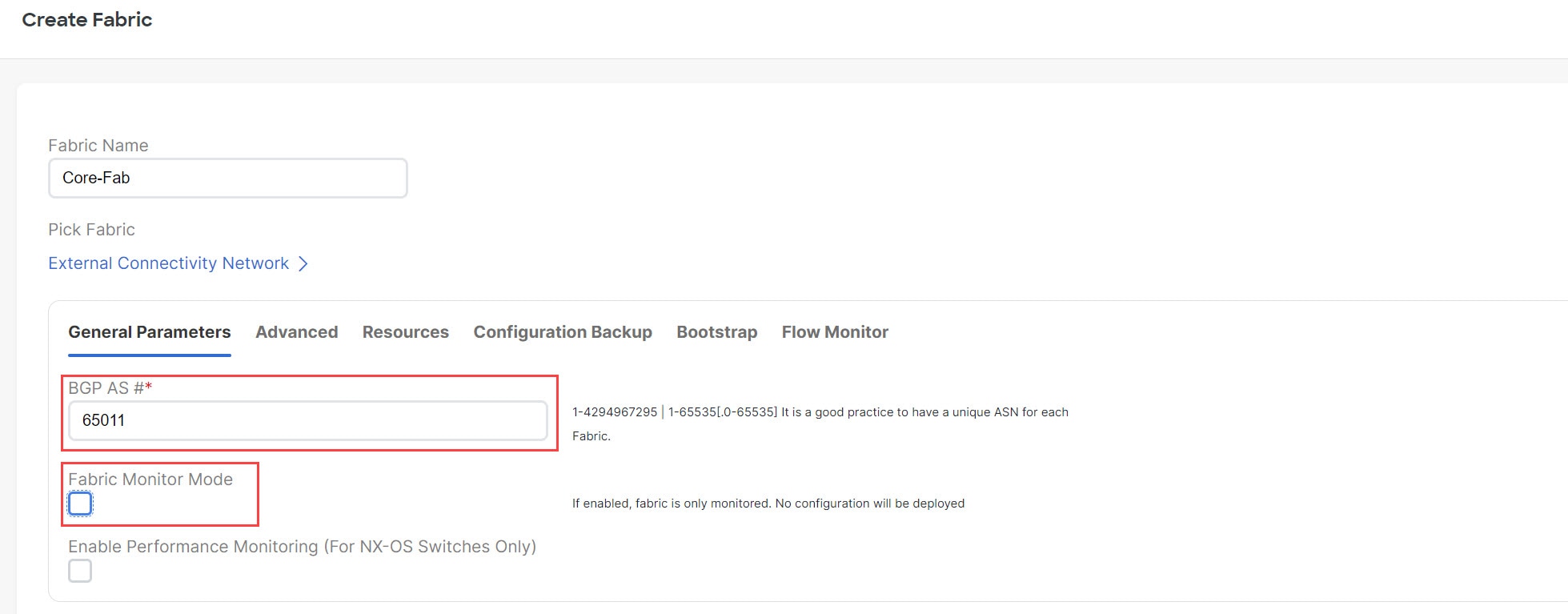
In the Create Fabric screen, enter a name for the Enhanced Classic LAN fabric (for example, |
||
|
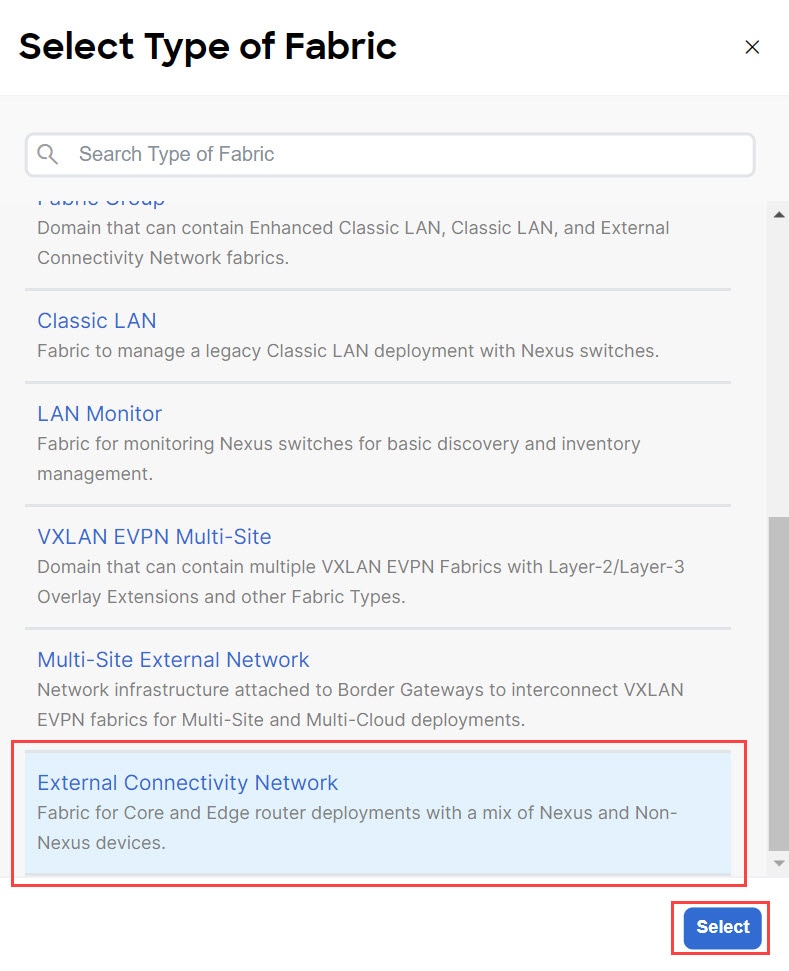
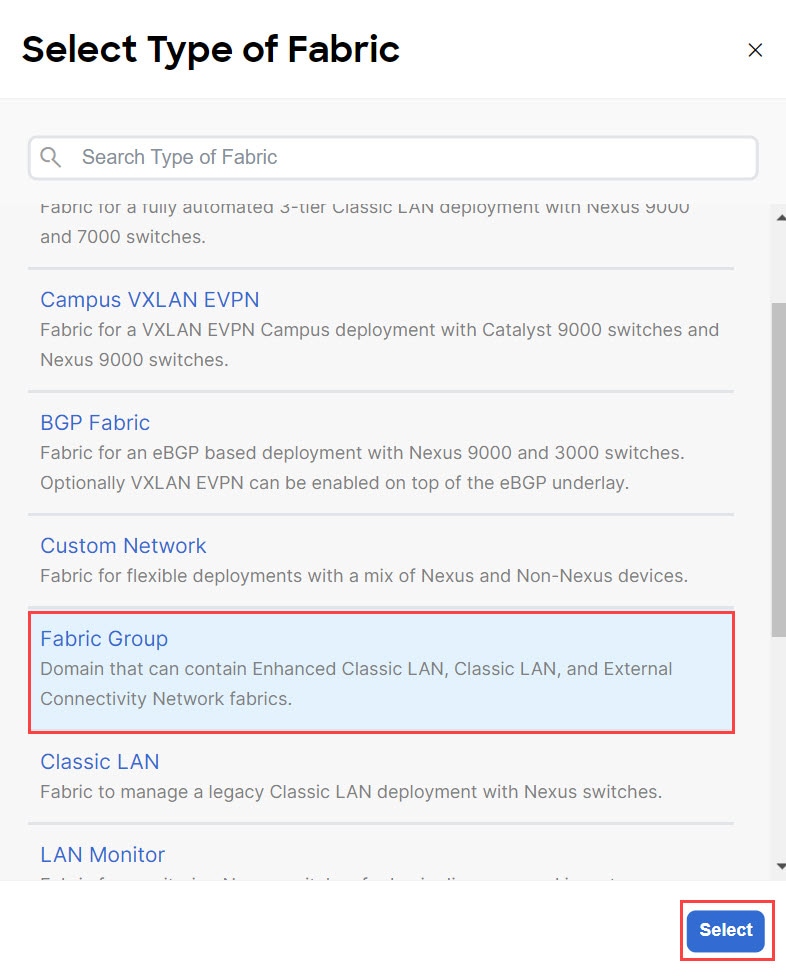
Step 4 |
Choose the 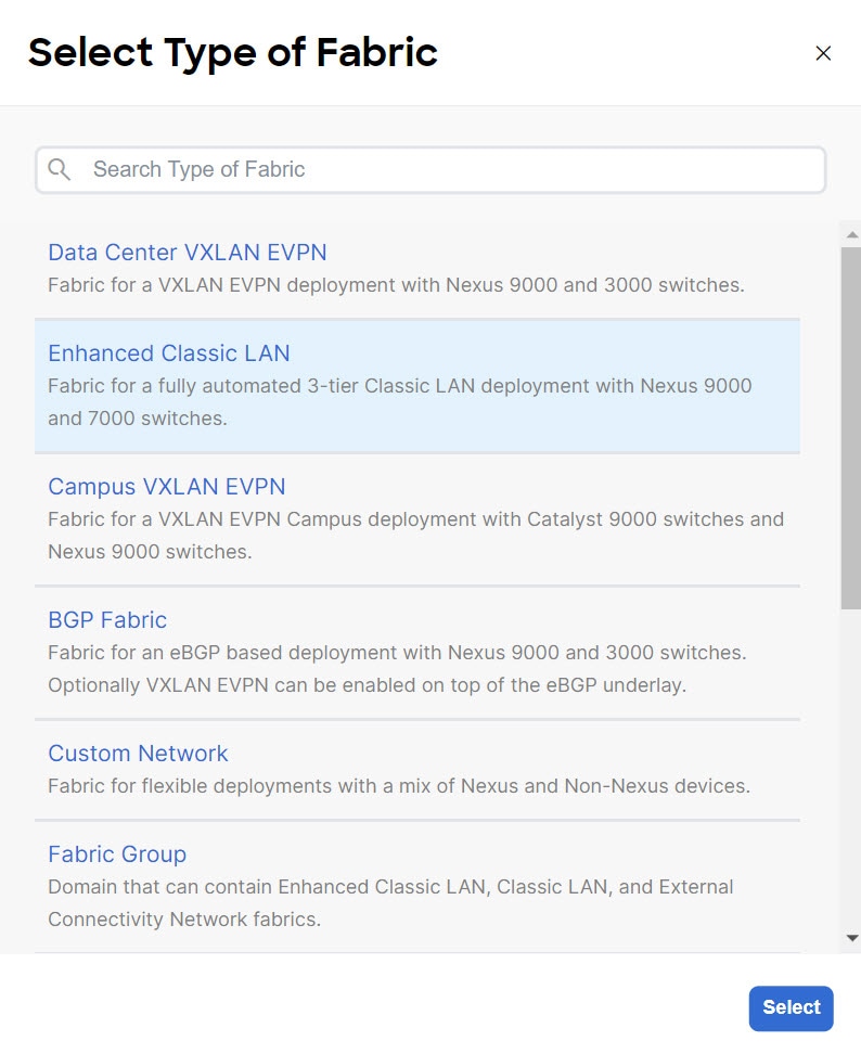
|
||
|
Step 5 |
In the General Parameters tab in the The following configurations are mandatory in the General Parameters page:
The remaining fields are optional. They have been automatically configured based on Cisco best practices, but you can change them if necessary. For example, in the General Parameters page. 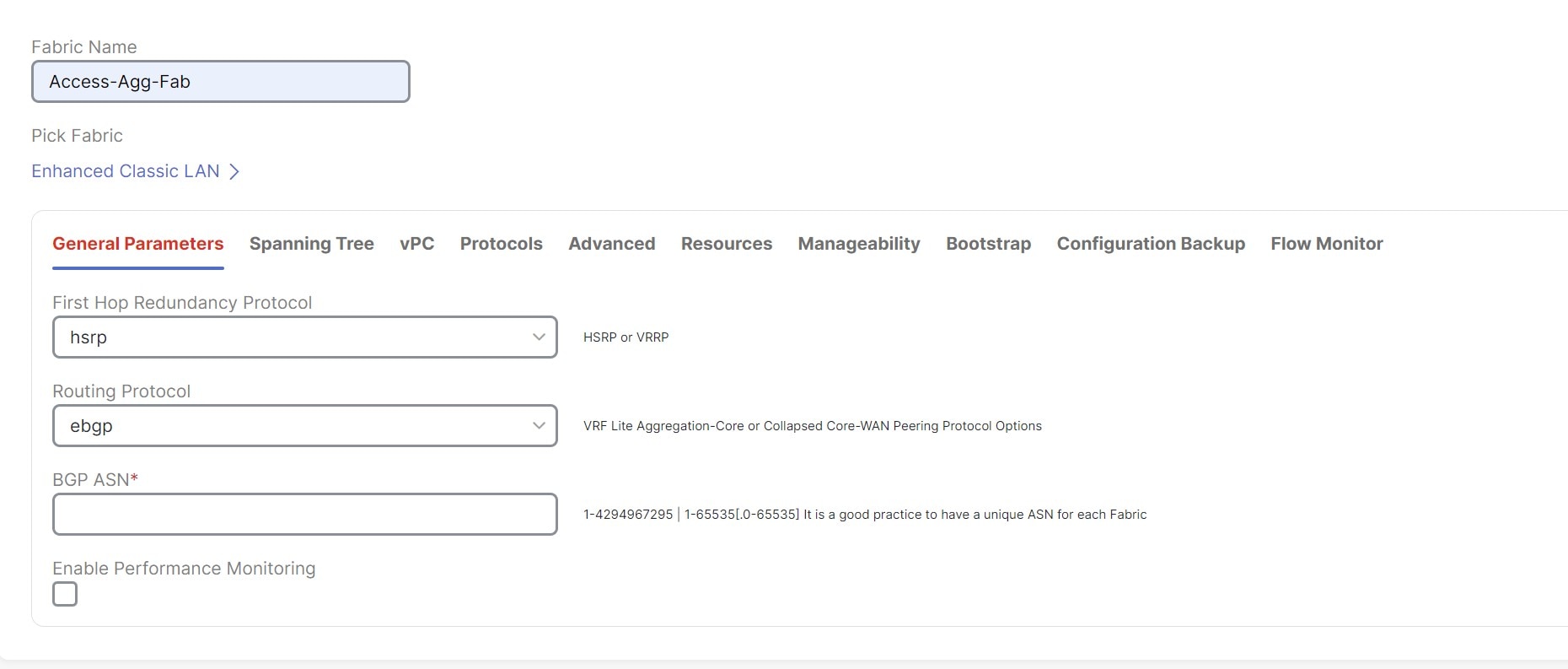
|
||
|
Step 6 |
In the Spanning Tree tab, make the necessary configurations for your setup. For example, in the Spanning-tree Root Bridge Protocol field, the 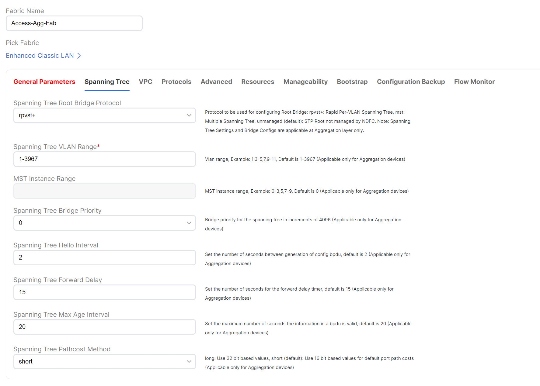
|
||
|
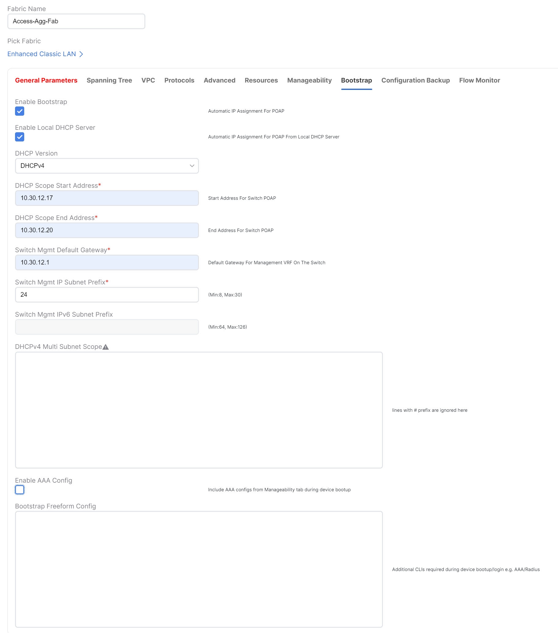
Step 7 |
In the Bootstrap tab, determine how you want NDFC to discover the switches in the Enhanced Classic LAN fabric. You can use either of these two methods to discover the switches in the fabric:
|
||
|
Step 8 |
Make any additional configurations to the template for the Enhanced Classic LAN fabric in the remaining tabs, if necessary. Updates to any of the values in the following tabs are all optional.
For more information on these fields in the Enhanced Classic LAN fabric template, see xref2:Enhanced Classic LAN KB article. |
||
|
Step 9 |
When you have completed the necessary configurations to the Enhanced Classic LAN fabric template, click Save. The LAN Fabric page appears again, with the newly created Enhanced Classic LAN fabric added to the list of configured fabrics. |
||
|
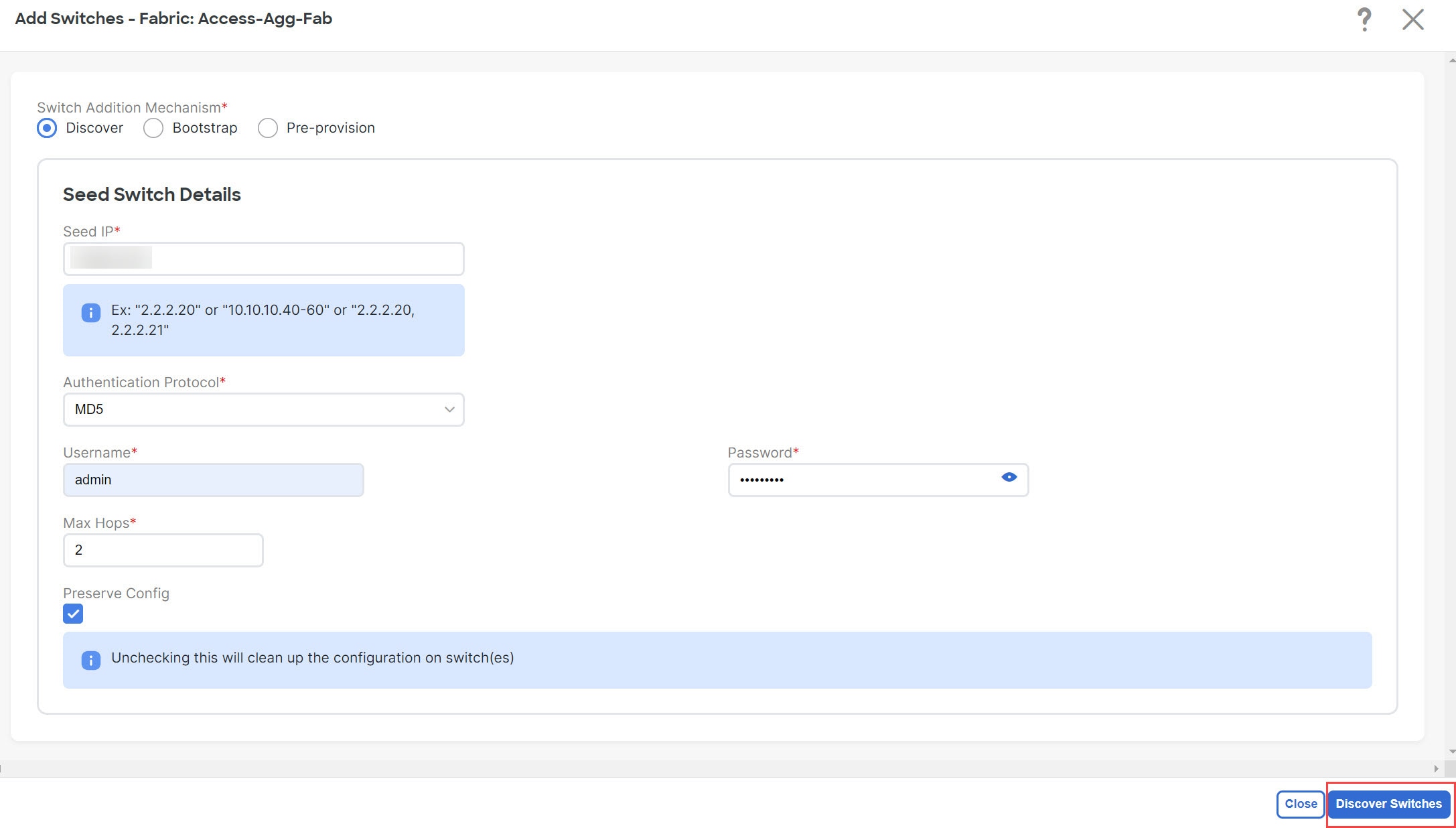
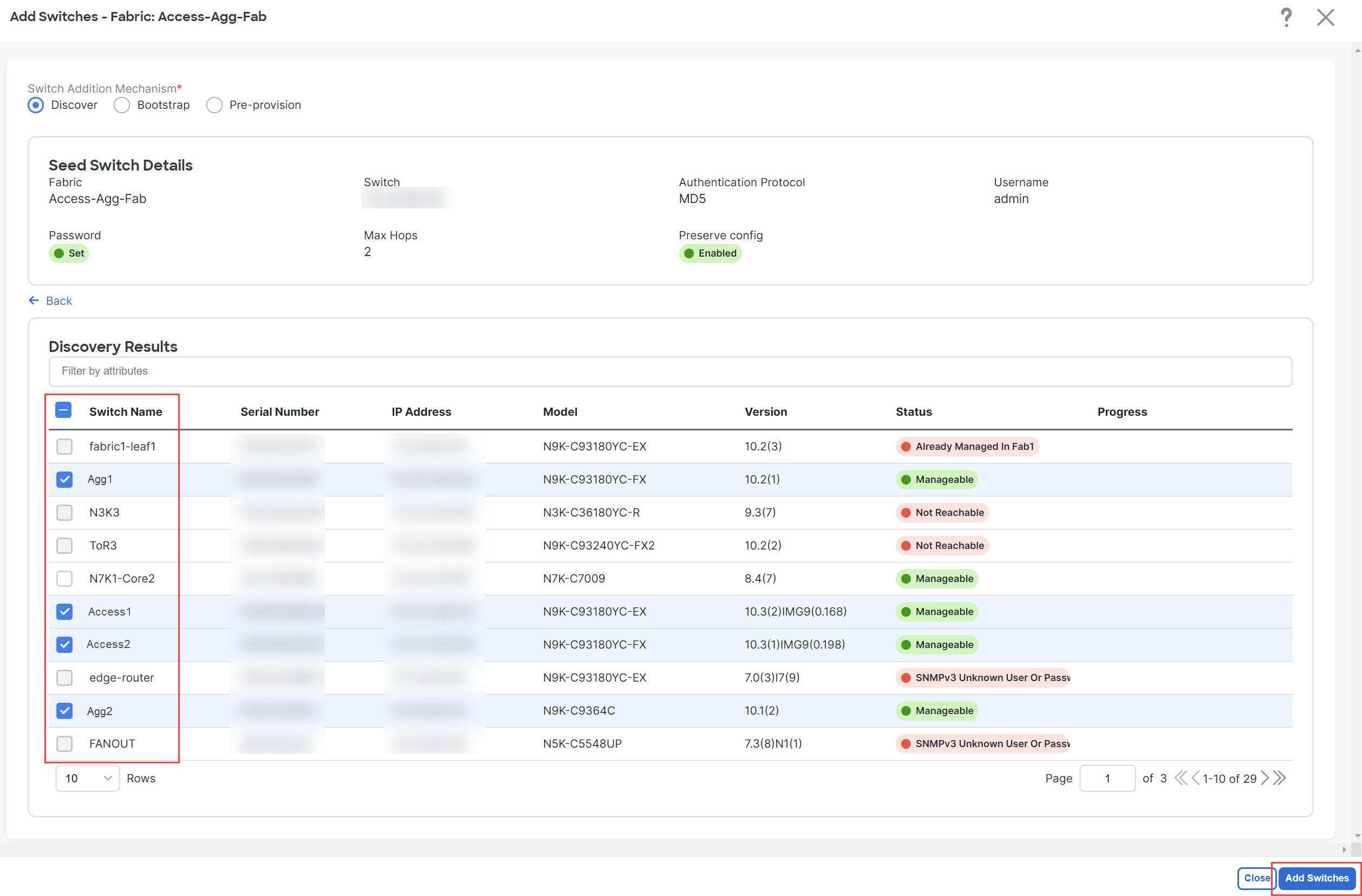
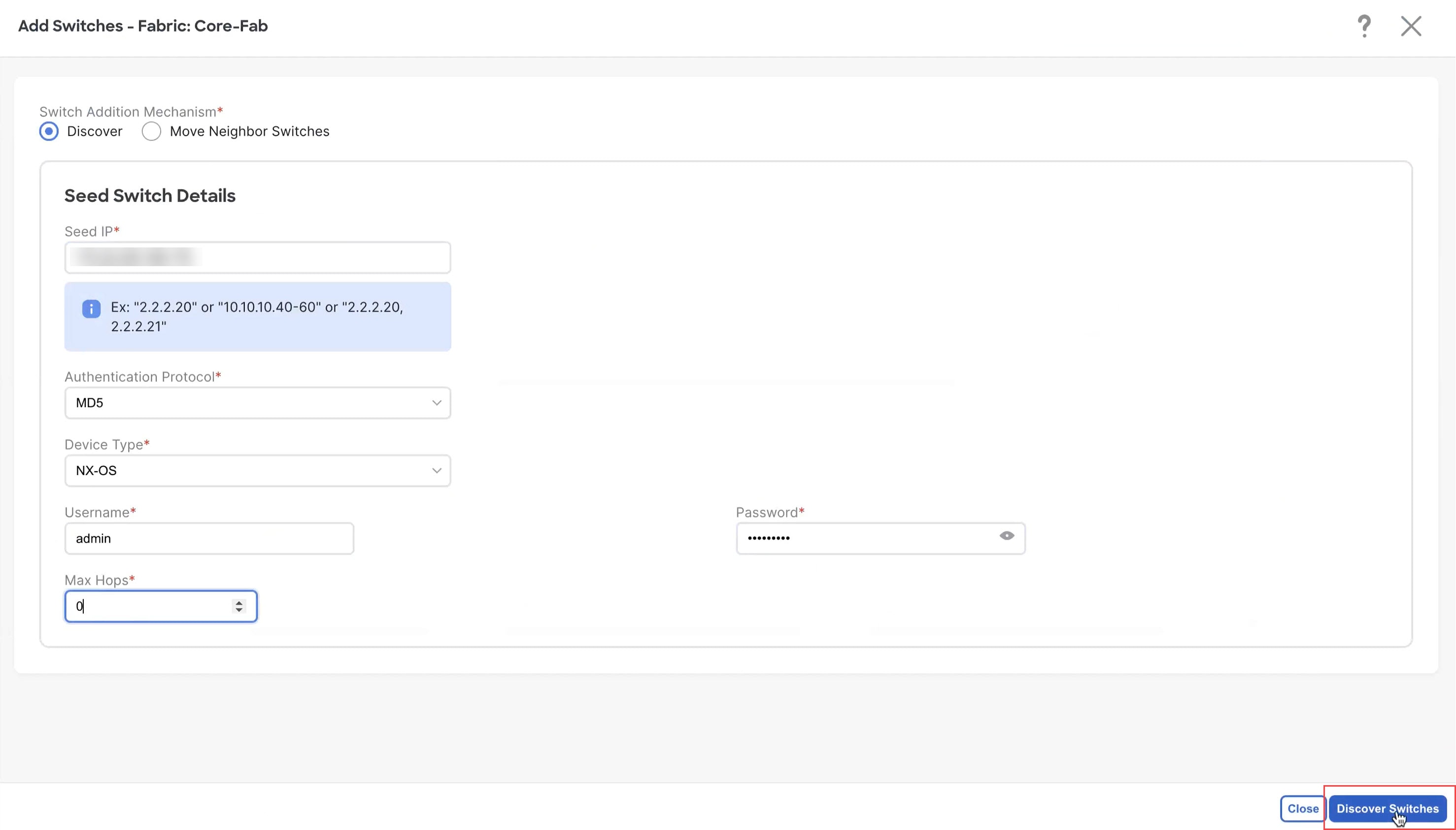
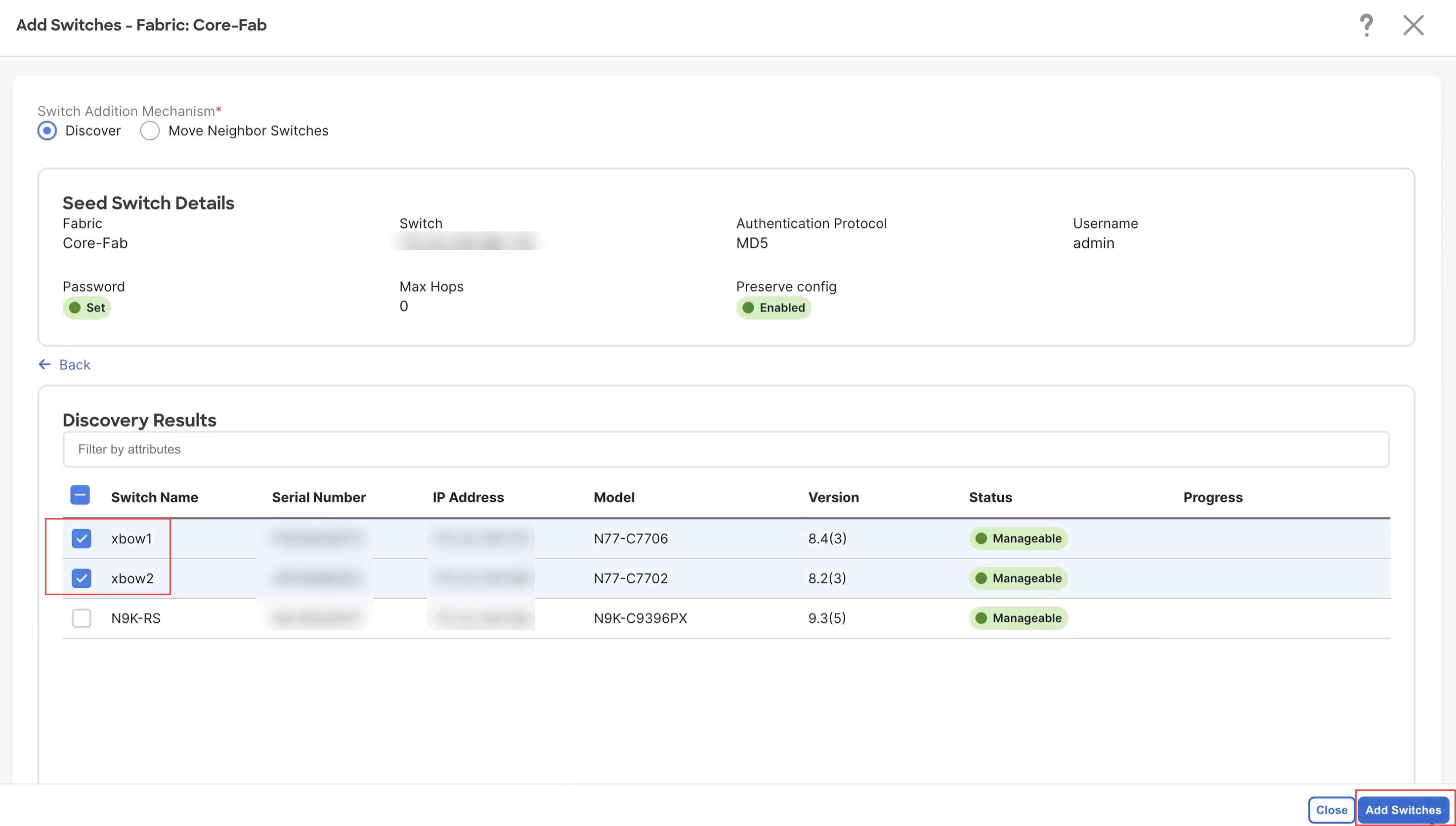
Step 10 |
If necessary, enter the necessary information to allow NDFC to discover the switches in the Enhanced Classic LAN fabric.
Verify that reachability exists between NDFC and these switches before proceeding with this step.
|
||
|
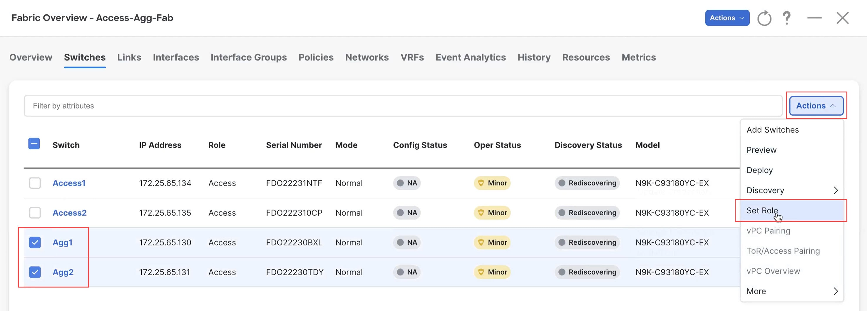
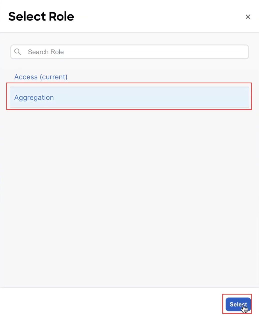
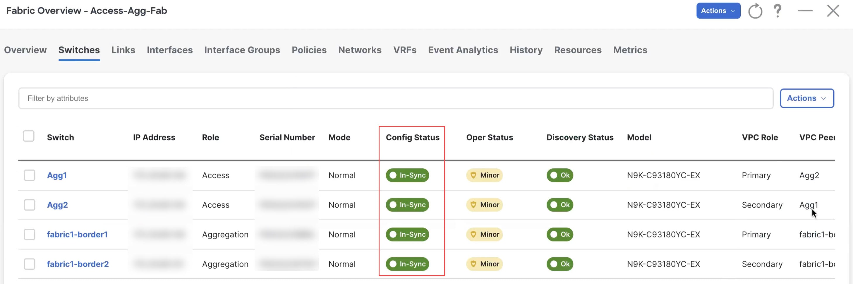
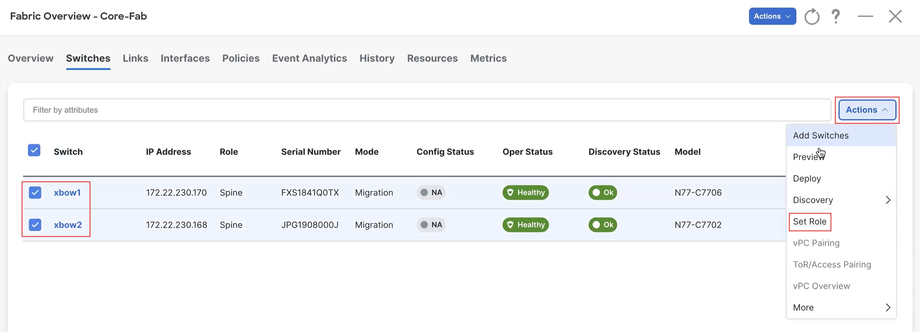
Step 11 |
Define the roles for the switches in the Enhanced Classic LAN fabric. Once the switches are discovered in the Enhanced Classic LAN fabric, the next step is to define the roles, or the intent, for those switches. Based on the roles that you assign to the switches, the appropriate configuration will be generated and pushed to the switches by NDFC. The following roles are available for the switches in the Enhanced Classic LAN fabric in this step:
|
||
|
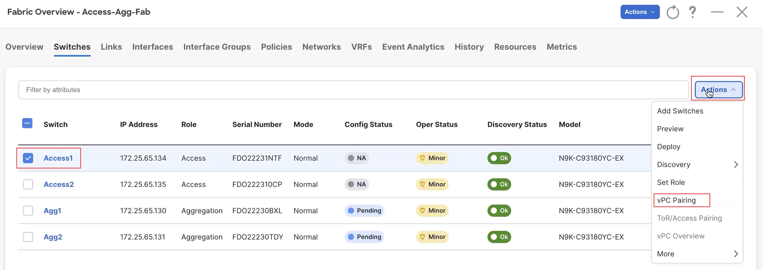
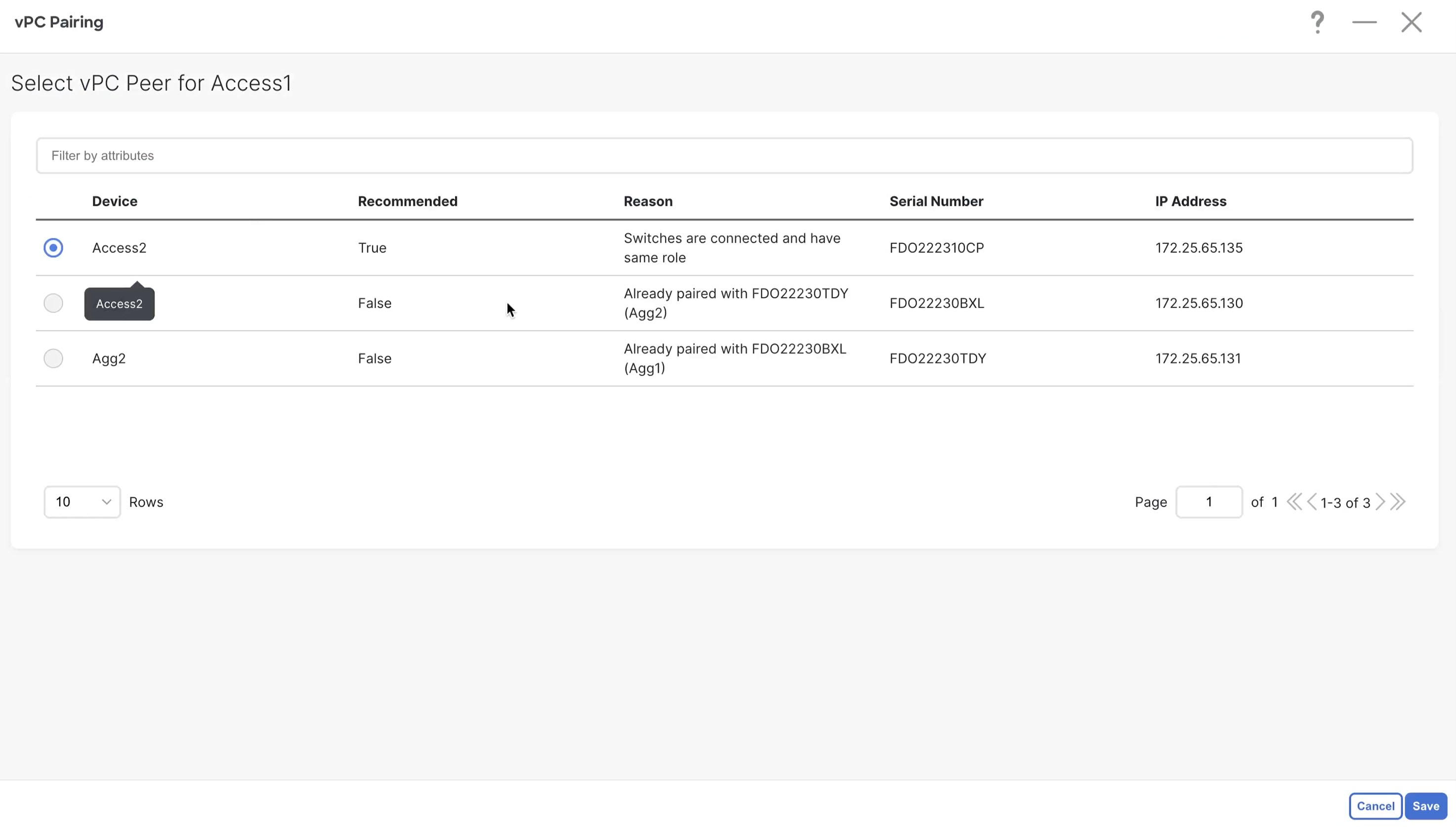
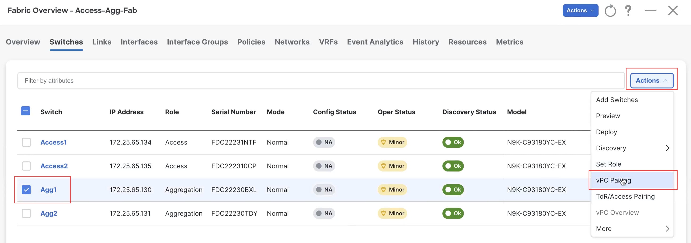
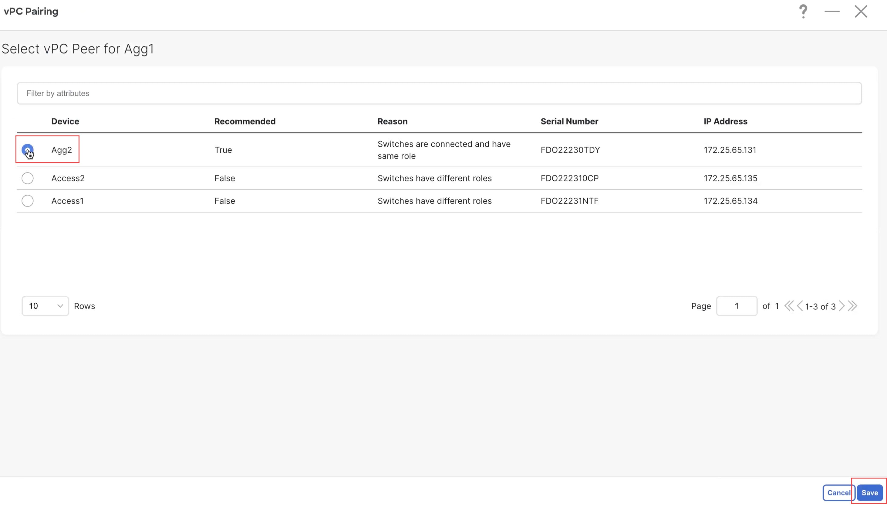
Step 12 |
Configure vPC pairing for the switches. Once the roles have been defined, you can configure vPC pairing for the switches that have been assigned Access or Aggregation roles.
For both types of switches, a related setting in the Advanced tab of Fabric Settings is enabled by default, which allows NDFC to automatically detect and pair Access or Aggregation switches for optimal traffic engineering. You can disable this feature, if desired, in the Enable Agg/Access Auto Pairing field in the Advanced tab. The following vPC pairing options are supported:
The following procedures apply, regardless of whether you are configuring a three-tier heirarchal network topology or a two-tier Collapsed Core topology:
|
||
|
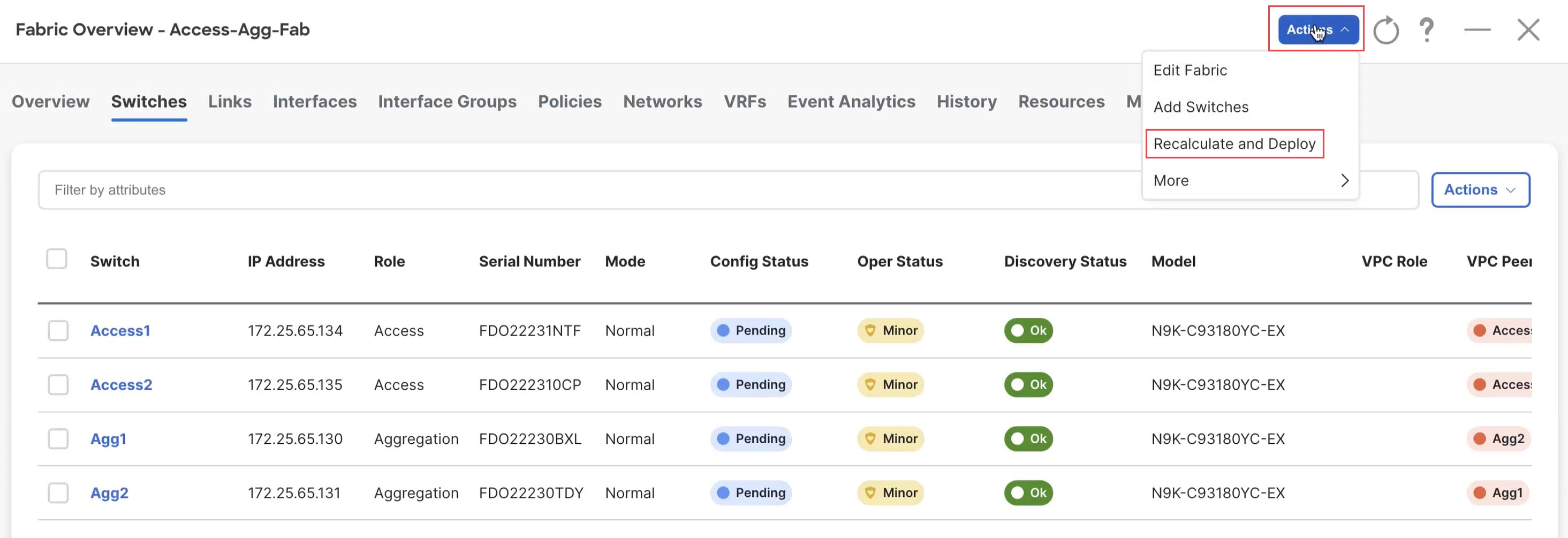
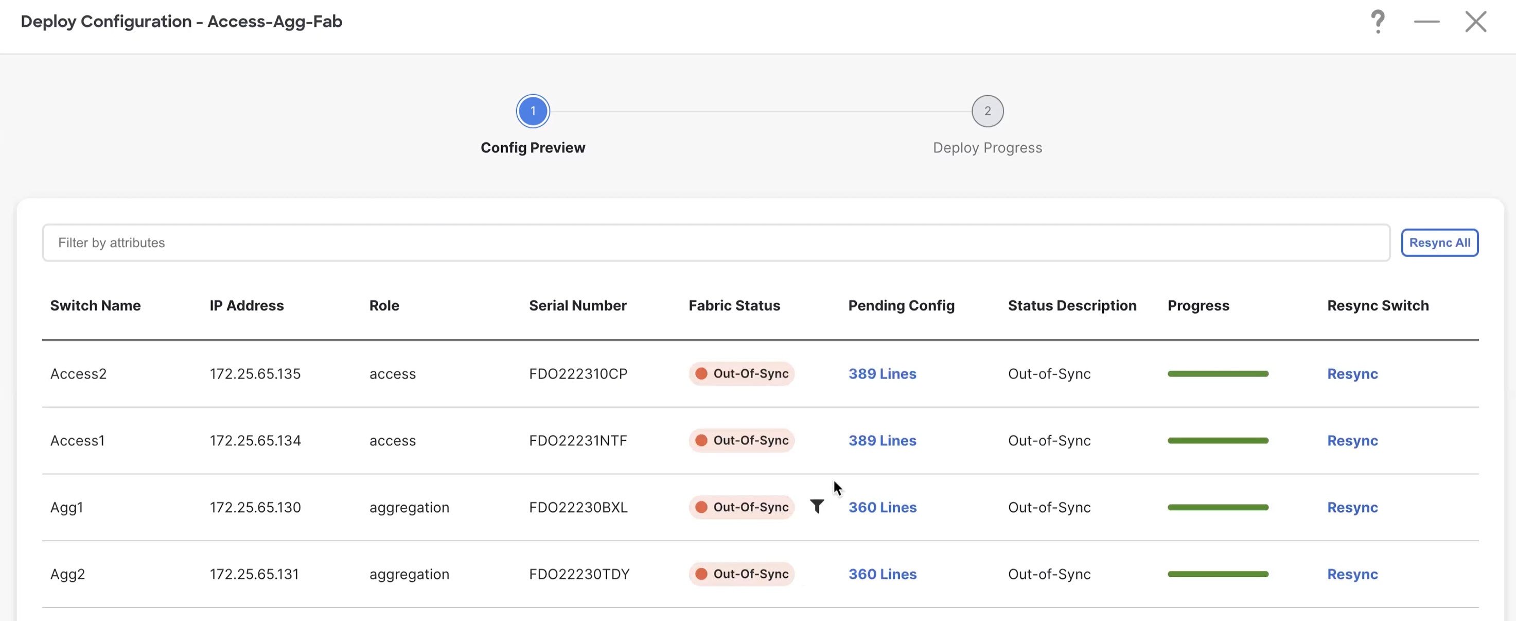
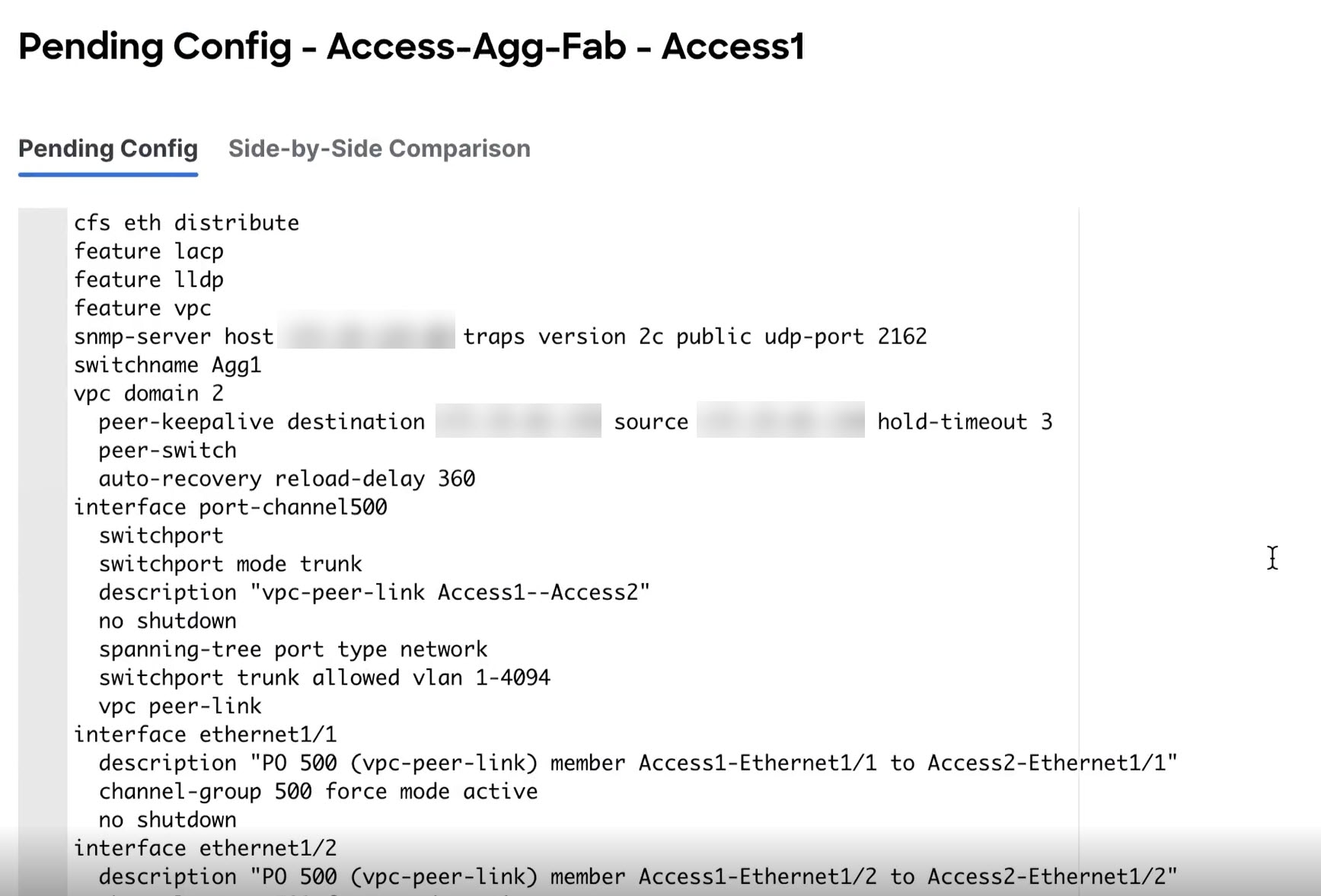
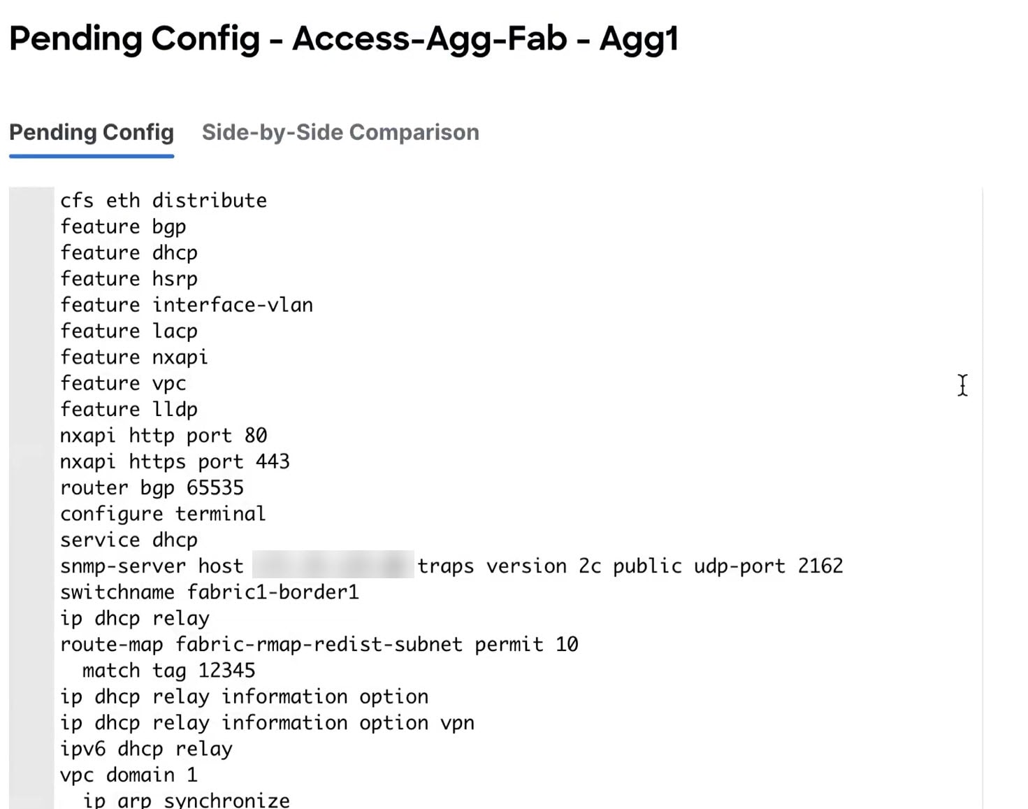
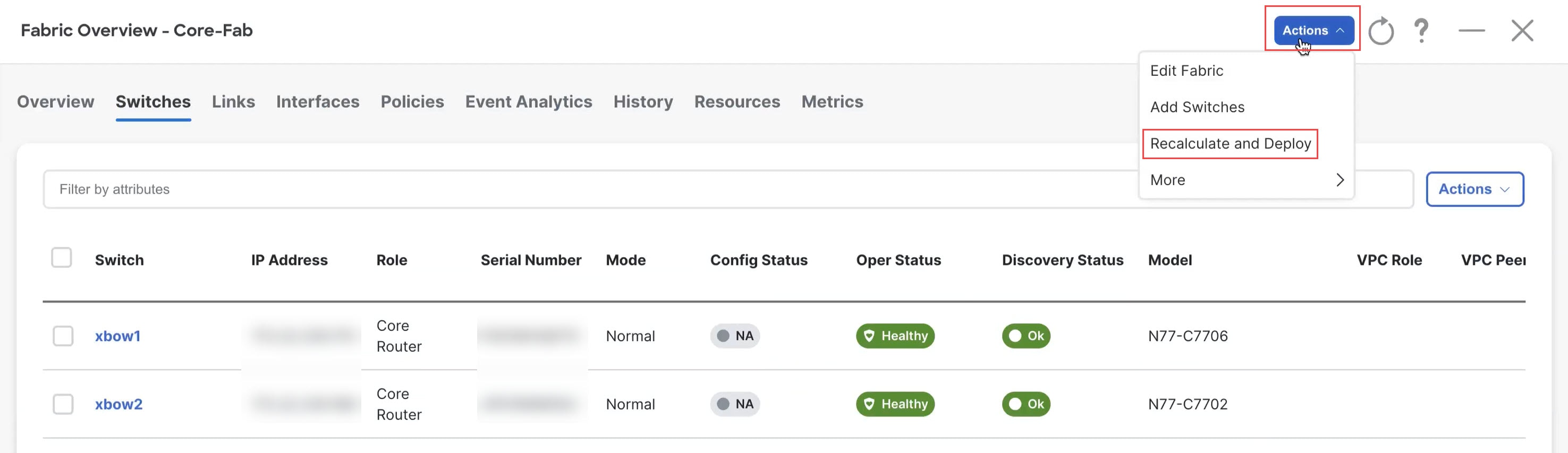
Step 13 |
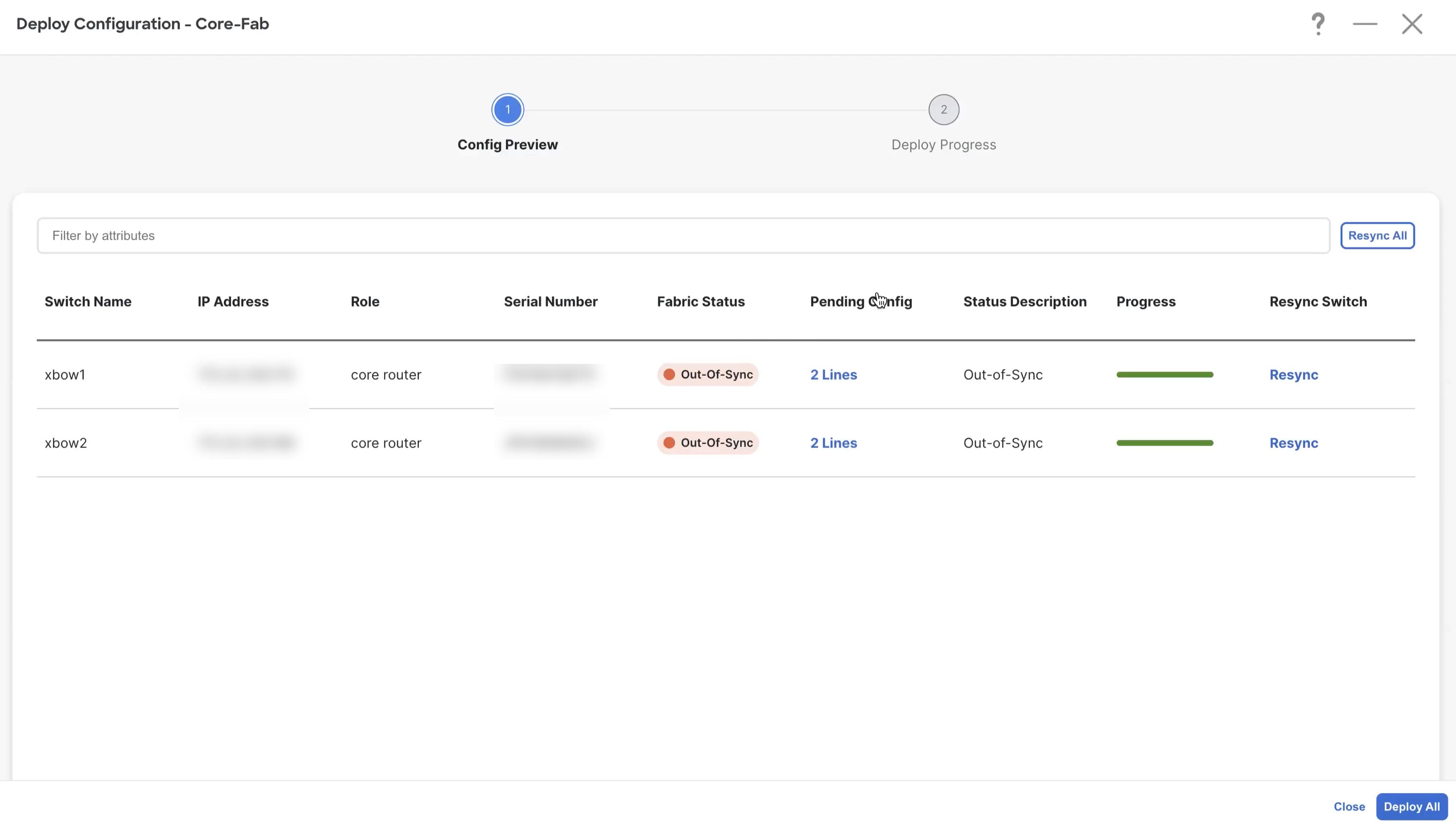
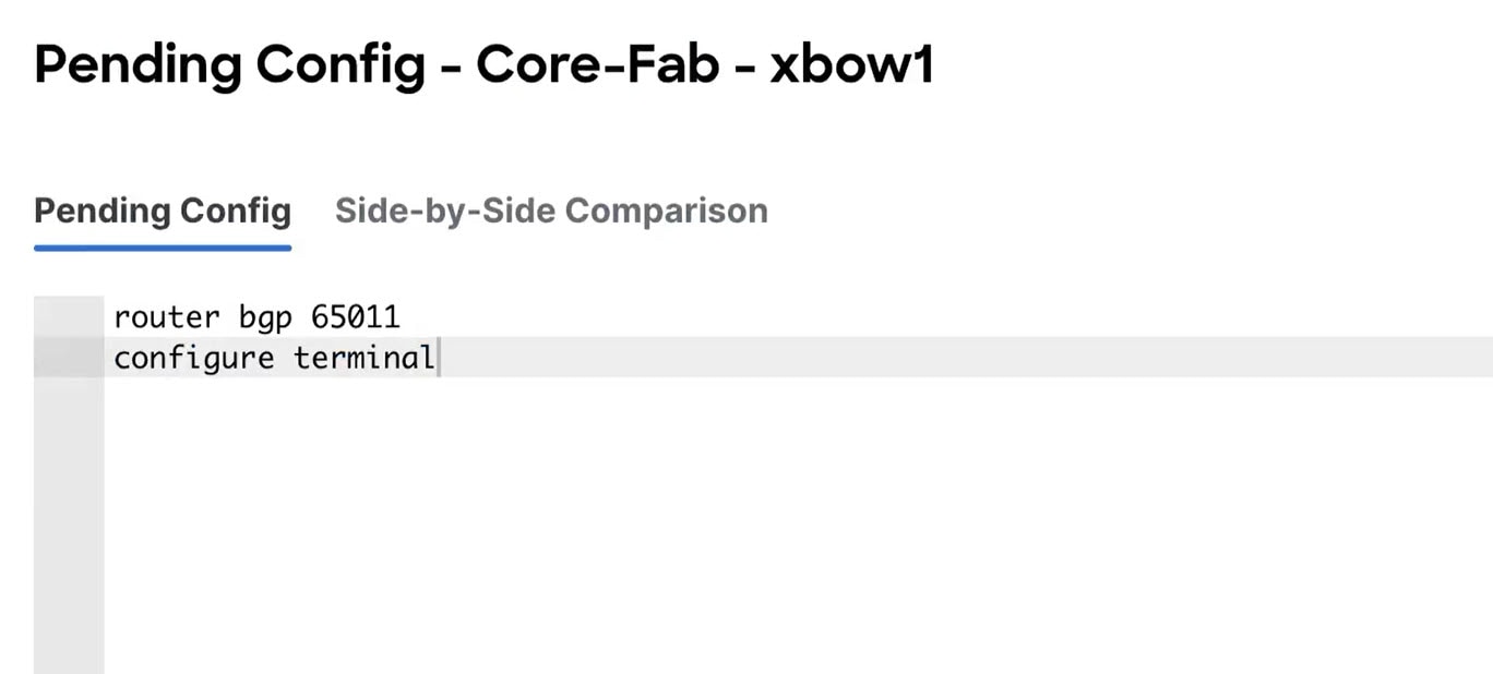
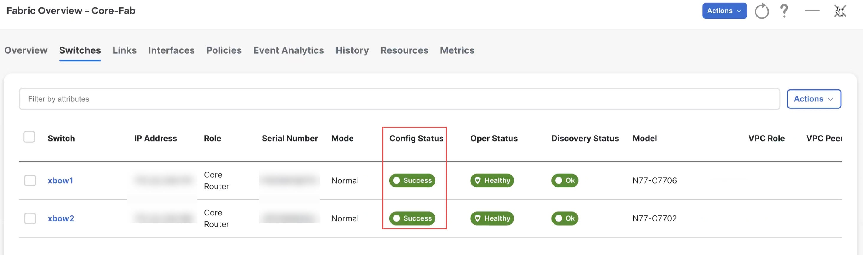
Recalculate and deploy.
|
What to do next
-
For a two-tier Collapsed Core topology, as described in Supported Legacy/Classic Network Topologies, you have completed the Day 0 configurations because the Enhanced Classic LAN fabric that you configured in this topic covers both tiers in a two-tier Collapsed Core topology. You are now ready to begin the Day 1 configurations. Go to Day 1 Configurations.
-
For a three-tier hierarchical topology, as described in Supported Legacy/Classic Network Topologies, you will configure the External Connectivity Network fabric that you will need for the Core tier next. Go to Configure the External Connectivity Network Fabric.

 Feedback