Understanding NDFC for Legacy/Classic Networks
This document describes how Cisco Nexus Dashboard Fabric Controller (NDFC) can be used to manage, maintain and monitor legacy/classic networks. In order to better understand how NDFC can be used to manage legacy/classic networks, it's useful to first understand all the pieces that are used in the process:
-
The following sections describe the software components that are used in this process:
-
Understanding Legacy/Classic Deployments describes information about standard legacy/classic deployments.
-
Supported Legacy/Classic Network Topologies describes the two topology types that are supported when managing a legacy/classic network through NDFC.
-
Understanding Access-Aggregation Device Attachments provides the different options for attaching the Access devices to the Aggregation devices.
-
Understanding How NDFC Fabric Templates Are Used to Manage Legacy/Classic Networks describes how NDFC fabric templates are used to manage these types of standard legacy/classic deployments.
Understanding ND
Cisco Nexus Dashboard (ND) is a central management console for multiple data center sites and a common platform for hosting Cisco data center operation applications, such as Nexus Dashboard Insights and Nexus Dashboard Orchestrator. These applications are universally available for all the data center sites and provide real time analytics, visibility, and assurance for network policies and operations. Cisco Nexus Dashboard Orchestrator can also run on Nexus Dashboard as a hosted app.
Nexus Dashboard provides a common platform and modern technology stack for the above-mentioned micro services-based applications, simplifying the life cycle management of the different modern applications and reducing the operational overhead to run and maintain these applications. It also provides a central integration point for external third-party applications with the locally hosted applications.
Each Nexus Dashboard cluster typically consists of one or three master nodes. For three-node clusters, you can also provision a number of worker nodes to enable horizontal scaling and standby nodes for easy cluster recovery in case of a master node failure. For maximum number of worker and standby nodes supported in this release, see the "Verified Scalability Limits" sections of the Cisco Nexus Dashboard Release Notes.
Understanding NDFC
Cisco Nexus Dashboard Fabric Controller, or NDFC (formerly known as Data Center Network Manager, or DCNM) is a service available exclusively on the Cisco Nexus Dashboard (ND) that uses a Kubernetes-based microservices architecture. NDFC provides comprehensive lifecyle management, configuration, and automation for a myriad of deployments using Cisco devices, such as NX-OS, IOS-XE, and IOS-XR devices, as well as non-Cisco devices.
In order to begin using NDFC, you must first have an ND cluster, where ND is deployed as a cluster of master and worker nodes in a virtual or physical form factor. The type and number of nodes required in a given cluster hosting NDFC depends on the scale of the managed switches, and whether NDFC will be used for LAN, SAN or Media Fabrics. It is possible to co-host NDFC with services like Insights in the same cluster, and to use NDFC for a variety of architectures at the same time, such as classic Ethernet and VXLAN.
You can use the NDFC Capacity planning tool to determine the number of ND nodes required for your scale. When the ND cluster is formed and healthy, NDFC can be installed from the Cisco App store, which is directly linked to the Nexus Dashboard. On enabling the service, the cluster will intelligently determine the resources required, depending on the scale and features enabled.
Understanding Legacy/Classic Deployments
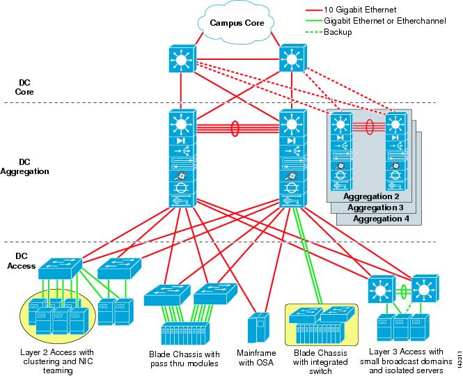
Typically, a legacy/classic data center deployment consists of three tiers or layers, as described in Data Center Multi-Tier Model Design:
-
Access layer: The access layer provides the physical level attachment to the server resources. The access layer is the first oversubscription point in the data center because it aggregates the server traffic onto Gigabit EtherChannel or 10 GigE/10 Gigabit EtherChannel uplinks to the aggregation layer. Spanning tree routing protocols are extended from the aggregation layer into the access layer, depending on which access layer model is used.
-
Aggregation layer: The aggregation layer is the Layer 3 and Layer 2 boundary for the data center infrastructure. Usually the aggregation layer is also the connection point for data center firewalls and other services. The aggregation layer, with many access layer uplinks connected to it, has the primary responsibility of aggregating the thousands of sessions leaving and entering the data center. The aggregation switches must be capable of supporting many 10 GigE and GigE interconnects while providing a high-speed switching fabric with a high forwarding rate. The aggregation layer also provides value-added services, such as server load balancing, firewalling, and SSL offloading to the servers across the access layer switches.
-
Core layer: The core layer provides the interconnection of multiple data center aggregation devices, providing a fabric for high-speed packet switching between multiple aggregation modules. This layer serves as the gateway to the campus core where other modules connect, including the extranet, WAN, and Internet edge. All links connecting the data center core are terminated at Layer 3 and typically use 10 GigE interfaces for supporting a high level of throughput and performance, and to meet oversubscription levels.
The following figure shows an example of a data center multi-tier model topology.
Supported Legacy/Classic Network Topologies
There are two types of legacy/classic network topologies that are supported, as described in the following sections.
Three-Tier Hierarchical Topology
In this type of legacy/classic network, the topology is split into three tiers:
-
Access
-
Aggregation
-
Core
The following graphic shows an example of this three-tier topology.
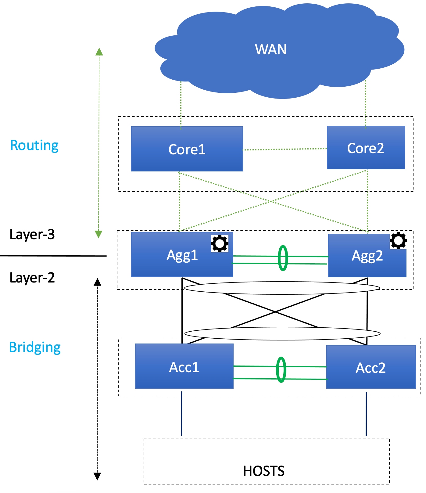
For this topology:
-
In this topology, the Layer 2/Layer 3 boundary occurs at the Aggregation level.
-
You will use the Enhanced Classic LAN fabric template to configure the fabric that will be used for the Access and Aggregation tiers, where you will be setting roles for the switches in this fabric to one of the following roles:
-
Access role: Access devices are usually attached to the end hosts or servers and have a Layer 2 configuration. You can configure Access devices as a vPC pair for better redundancy.
-
Aggregation role: Aggregation devices are always deployed in an Enhanced Classic LAN fabric as a vPC pair. There can be multiple Aggregation vPC pairs in a single Enhanced Classic LAN fabric. Aggregation or distribution devices typically present the Layer-2/Layer-3 boundary, so you can enable the appropriate SVIs with your desired First Hop Redundancy Protocol (FHRP) at this layer. All routed (intra-subnet) traffic is forwarded through the Aggregation layer.
-
-
You will use the the External Network Connectivity fabric template to configure the fabric that will be used for the Core tier, where you will be setting the role for the switches in this fabric to the Core Router or the Edge Router role.
See Understanding How NDFC Fabric Templates Are Used to Manage Legacy/Classic Networks for more information on the two fabric template types.
 Note |
There is only one Aggregation pair shown in the preceding figure; however, for greenfield deployments, you could have multiple Aggregation pairs when you have this sort of topology managed by Cisco Nexus Dashboard Fabric Controller. |
Two-Tier Collapsed Core Topology
In this type of legacy/classic network, the topology is split into two tiers:
-
Access
-
Collapsed Core
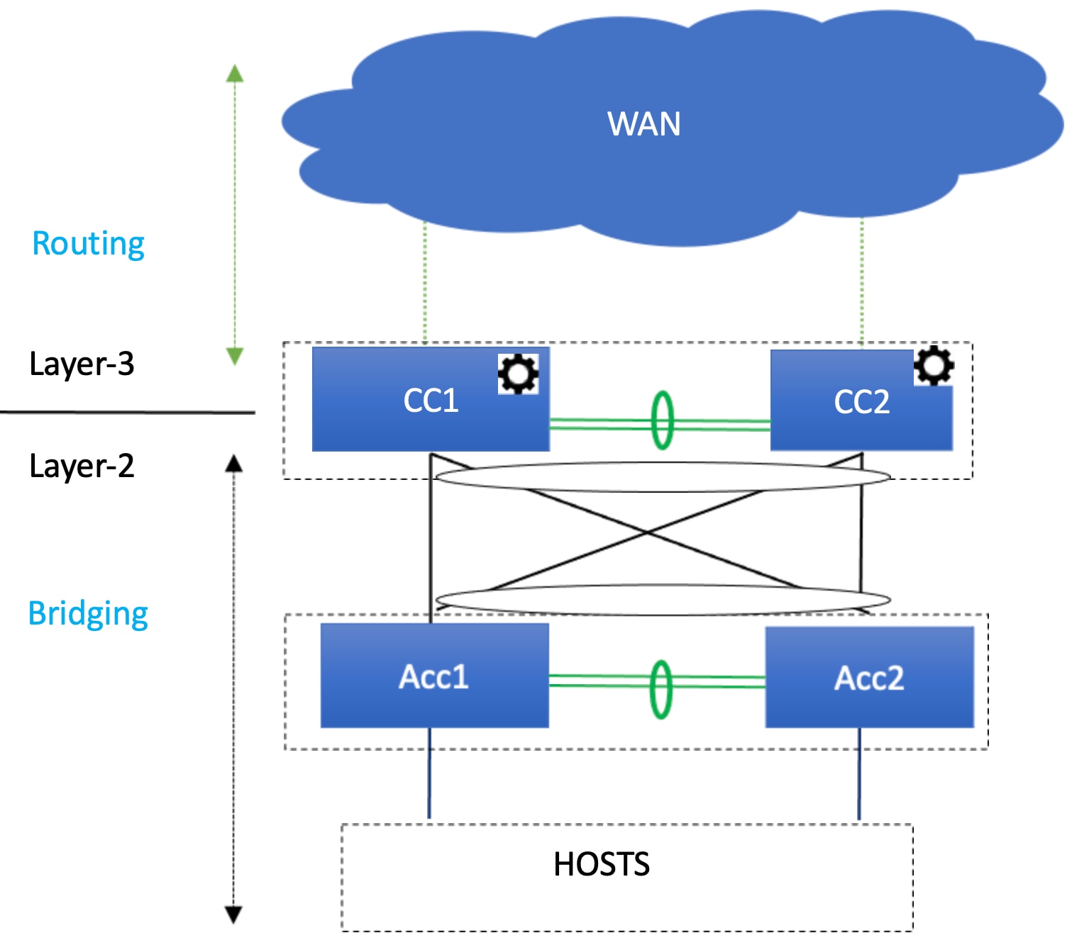
For this topology:
-
In this topology, the Core and Aggregation tiers are collapsed into a single, combined tier, called the "Collapsed Core" tier. The Layer 2/Layer 3 boundary occurs at the Collapsed Core tier.
-
You will use the Enhanced Classic LAN fabric template to configure the fabric that will be used for the Collapsed Core tiers. See Understanding How NDFC Fabric Templates Are Used to Manage Legacy/Classic Networks for more information.
Switches Used At Each Tier
In typical legacy/classic networks using Cisco equipment:
-
Cisco Nexus 7000 Series switches are deployed at the aggregation and core layers, though these switches are used mainly at the aggregation layer
-
Cisco Nexus Nexus 5000 and 6000 Series switches are deployed at the access layer
-
You might also have Cisco Nexus 2000 Series Fabric Extender switches attached to either the aggregation or the access layers, though these switches are typically attached to the access layer
-
Cisco Nexus 3000 and 9000 Series switches might be used at the core, aggregation or access layers
When using the new Enhanced Classic LAN fabric template in NDFC, Cisco Nexus 2000, 3000, 7000, and 9000 Series switches are supported, in these areas:
-
Cisco Nexus 2000 Series Fabric Extender switches might be used at the access layer
-
Cisco Nexus 7000 Series switches might be used at the aggregation layer
-
Cisco Nexus 3000 and 9000 Series switches might be used at the aggregation or access layers
In addition, at the core layer, Cisco Nexus 3000, 7000, or 9000 Series switches, or possibly Catalyst 9000 or ASR 9000 Series switches, could be used because the Core role is present in the External fabric and not in the Enhanced Classic LAN fabric.
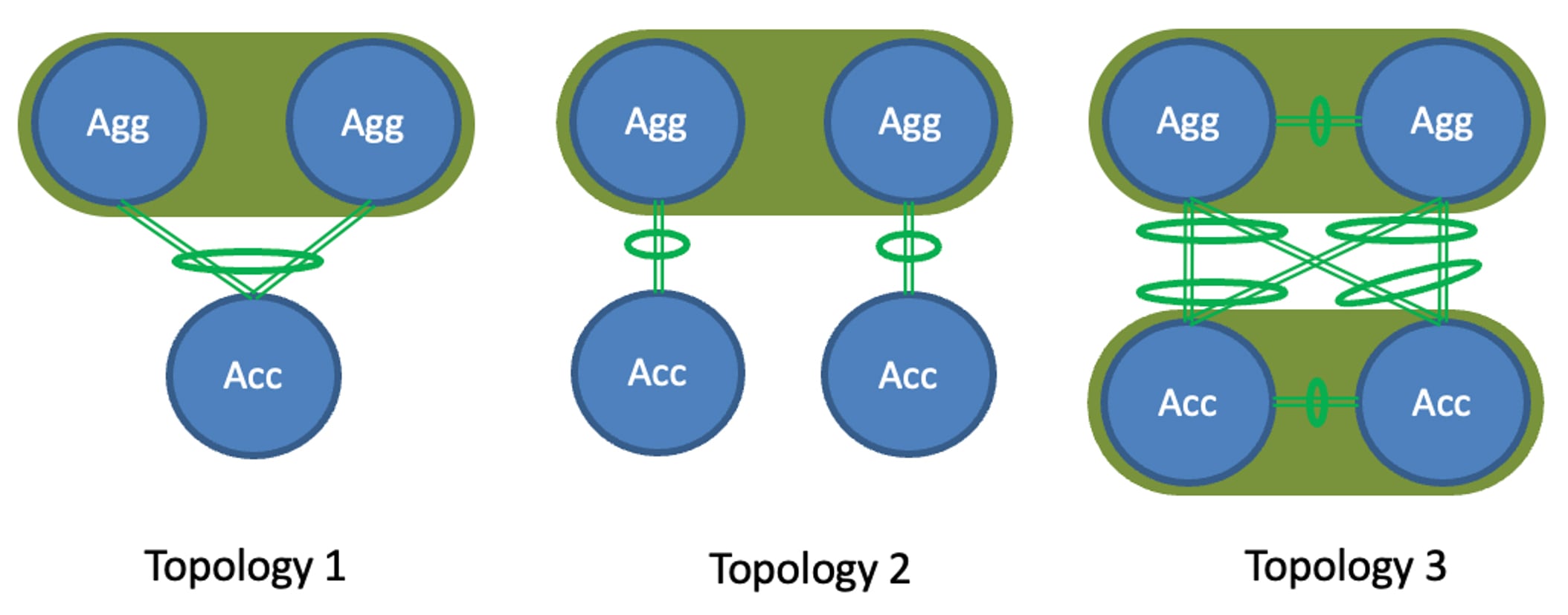
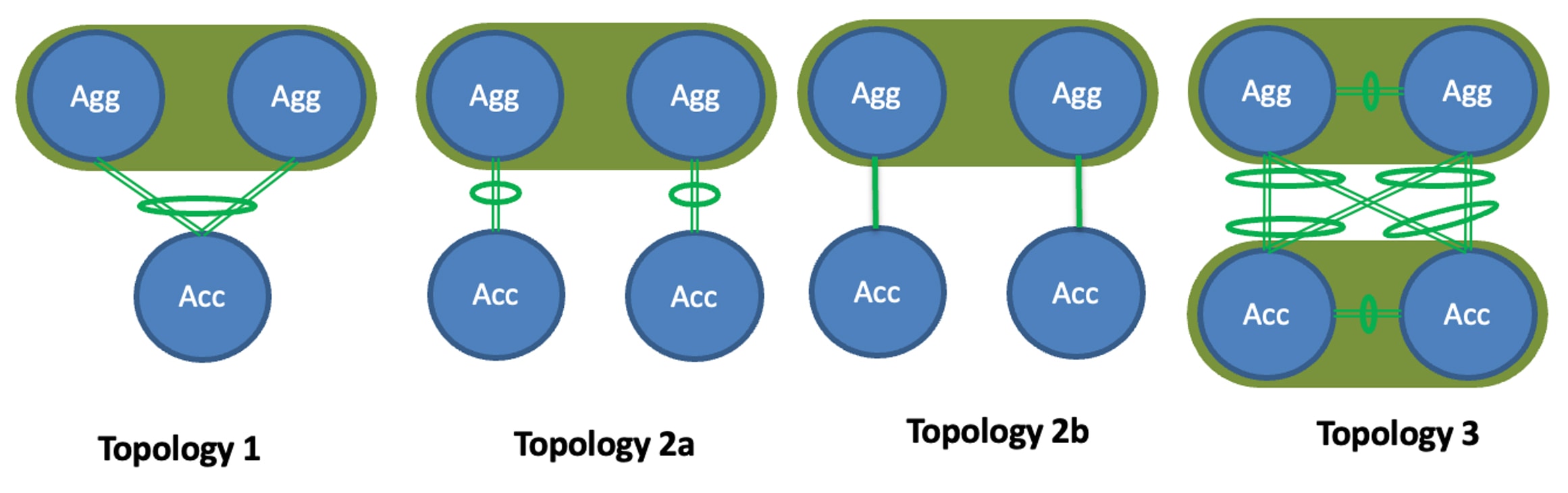
Understanding Access-Aggregation Device Attachments
For the three-tier hierarchical topology described in Supported Legacy/Classic Network Topologies, the Access devices can be attached to the Aggregation devices using one of the following options:
-
Topology 1: vPC Aggregation pairing with the same Access (one Access device connected to both Aggregation devices), such as using a Fabric Extender in active-active (FEX-AA) mode for the Access device.
-
Topology 2: vPC Aggregation pairing with a separate Access (each Access device connected to one of the Aggregation devices), such as using a Fabric Extender in straight through (FEX-ST) mode for the Access device.
-
Topology 3: vPC Aggregation pairing with vPC Access through back-to-back vPC pairings.
For any of these Access-Aggregation device connections, when you select Recalculate and Deploy after you have finished entering the necessary configuration information in the Enhanced Classic LAN fabric template, NDFC will automatically detect the connectivity between the Access and Aggregation layer devices and will generate the appropriate configurations based on the supported topologies above that were detected.
Note |
If you have an Access-Aggregation device connection that does not fall into one of the supported topologies above, NDFC will return an error when you select Recalculate and Deploy after you have finished entering the necessary configuration information in the Enhanced Classic LAN fabric template. |
Understanding How NDFC Fabric Templates Are Used to Manage Legacy/Classic Networks
As part of the process for managing legacy/classic networks through NDFC, you will use different NDFC fabric templates to create the fabrics that will be used for the different tiers:
-
Enhanced Classic LAN fabric template: The Enhanced Classic LAN fabric template is used to configure the fabric for one of the following types of tiers, as described in Supported Legacy/Classic Network Topologies:
-
For a three-tier topology, you will use the Enhanced Classic LAN fabric template to configure the fabric that will be used for the Access and Aggregation tiers.
-
For a two-tier (Collapsed Core) topology, you will use the Enhanced Classic LAN fabric template to configure the fabric that will be used for both tiers in that topology.
-
-
External Network Connectivity fabric template: The External Network Connectivity fabric template is used to configure the fabric specifically for the Core tier in a three-tier topology, as described in Supported Legacy/Classic Network Topologies.
 Feedback