
New and changed information
The following table provides an overview of the significant changes up to this current release. The table does not provide an exhaustive list of all changes or of the new features up to this release.
| Release Version | Feature | Description |
|---|---|---|
|
Nexus Dashboard 4.1.1 |
Improved navigation and workflow when working with inventory for LAN and IPFM fabrics |
Beginning with Nexus Dashboard 4.1.1, Nexus Dashboard enhanced the navigation and workflow when working with inventory for LAN and IPFM fabrics. |
|
Nexus Dashboard 4.1.1 |
Support for leaf-ToR pairing for a Data Center VXLAN EVPN eBGP fabric |
With this release, Nexus Dashboard added support for leaf-ToR pairing for a Data Center VXLAN eBGP fabric. The same functionality that is available for leaf-ToR pairing in a Data Center VXLAN EVPN iBGP fabric is also available for a Data Center VXLAN EVPN eBGP fabric. For more information, see Configuring ToR switches and deploying networks in Data Center VXLAN EVPN fabrics. |
|
Nexus Dashboard 4.1.1 |
Support for visualization of port status information for IPFM fabrics |
With this release, Nexus Dashboard added support for viewing switch port utilization for IPFM fabrics. You can view port status information such as the operational status, anomaly level, and Layer 3 neighbor for an interface. For more information, see View switch port status information for IPFM fabrics. |
Navigate to the Inventory page
Navigate to the Inventory page to view or edit switch information. You can navigate to the Inventory page using either of these methods:
-
To view inventory information at the Nexus Dashboard level, click Manage > Inventory.
-
To view inventory information at an individual fabric level:
-
Click Manage > Fabrics.
-
Click the appropriate fabric on the Fabrics page.
-
Click the Inventory tab.
-
View information on all switches in a fabric
To view information on all switches in your fabric:
-
Navigate to Switches, if necessary.
If you navigated to the Inventory page from the fabric, click Inventory > Switches.
The Switches page shows information on already-configured switches in your fabric. The following table describes the fields that appear on the Switches page.
Field Description Name
Specifies the name of the switch.
Fabric Name
Available if you navigated to the Inventory page using Manage > Inventory. Specifies the fabric that contains the switch.
Anomaly level
Displays the anomaly level of the switch. Anomalies are classified into these levels:
-
Critical: Shown when the switch is down, such as when a switch is not operational.
-
Major: Shown when connectivity to a given prefix or endpoint could be compromised, such as overlapping IP addresses.
-
Warning: Shown when the switch is impacted, such as when connectivity to a given prefix or endpoint is degraded.
IP Address
Specifies the IP address of the switch.
Model
Specifies the switch model.
Configuration Sync Status
Specifies the configuration status. Status will be either In-Sync or Out-of-sync.
Role
Specifies the role assigned on the switch.
Serial Number
Specifies the serial number of the switch.
Discovery Status
Specifies the discovery status of the switch.
Advisory level
Displays the advisory level of the switch. Advisories are classified into these levels:
-
Critical: Shown when there are unsupported infrastructure and the severity of the bugs associated with notices is Severity1, such as when switches in a fabric are running under End-of-Life conditions or when a critical (Severity1) field notice or PSIRT has been issued for a switch or software version currently running in your network.
-
Major: Shown when the severity of the bugs associated with notices is Severity2, such as when a critical (Severity2) field notice or PSIRT has been issued for a switch or software version currently running in your network.
-
Warning: Shown when there is support for potentially at-risk infrastructure and the severity of the bugs associated with notices is Severity3, such as when switches in a fabric are approaching end-of-life conditions, or when a Severity3 field notice or PSIRT has been issued for a switch or software version currently running in your network.
vPC Role
Specifies the vPC role of the switch.
vPC Peer
Specifies the vPC peer with the switch.
Mode
Specifies whether the switch is in Normal or Maintenance mode. For more information, see Perform actions on switches for more information.
Software Version
Specifies the software version that is running on the switch.
Uptime
Specifies the amount of time that the switch has been up.
-
Configure switches
The following sections provide information on configuring switches in your LAN or IPFM fabric.
Add switches to a fabric
Nexus Dashboard has two logical interfaces per node: management interface (bond1br) and fabric (also known as data) interface (bond0br). For Nexus Dashboard, management and fabric interfaces must be in different IP subnets. By default, the route for Nexus Dashboard functionality is through the fabric interface. An operator must add static routes on the Nexus Dashboard management network to connect with switches that must be reached over a management interface (bond1br). This ensures that a route for the pods uses a management interface as the exit interface.

When performing discovery or adding switches or LAN credentials to Nexus Dashboard, make sure that the switch user has the network-admin role.
SNMPv3 is used to discover Nexus devices. When a user is created on the switch, the same username/password is used by default for SNMPv3 authentication.
To add switches to the existing fabric, perform the following procedure:
-
Navigate to Switches, if necessary.
If you navigated to the Inventory page from the fabric, click Inventory > Switches.
-
Choose Actions > Add Switches.
The Add Switches page appears.
-
Choose a fabric, if necessary.
If you navigated to the Inventory page from Manage > Inventory, you must choose a fabric where you will add the switch.
The Discover radio button is selected by default.
Similarly, you can add switches on the Topology page. On this page, choose a fabric, right-click the fabric, and click Add Switches.
-
If you were already in a fabric when you clicked Actions > Add Switches, the Add Switches - Fabric: fabric-name page appears.
-
If you adding a switch from the Nexus Dashboard level:
-
On the Add Switches page, click Choose Fabric.
-
On the Select Fabric page, click the appropriate fabric, then click Select. The Add Switches - Fabric: fabric-name page appears.
-
-
Also, you can pre-provision switches and interfaces. For more information, see Pre-provision a device and Pre-provision an Ethernet interface.
Nexus Dashboard supports LAN switch discovery for Cisco Nexus 9000 (N9K) devices only when those devices use the default CDP device-ID format. The command cdp format device-id system-name is not supported for N9K discovery. Ensure that N9K devices, including peer N9K devices discovered through CDP, use the default CDP format by configuring no cdp format device-id system-name.
When Nexus Dashboard discovers a switch with the hostname containing the period character (.), it is treated as a domain name and truncated. Only the text before the period character (.) is considered as a hostname. For example:
-
If the hostname is leaf.it.vxlan.bgp.org1-XYZ, Nexus Dashboard shows only leaf
-
If the hostname is leaf-itvxlan.bgp.org1-XYZ, Nexus Dashboard shows only leafit-vxlan
Ensure that the switch name or the host name is unique within the fabric.
Discover new switches
Before discovering a new switch, verify that the password for that switch has eight characters or more. Even though Nexus Dashboard allows you to discover a switch that has a password length of fewer than eight characters, you might see the error message "Unexpected error during post add processing" when adding a switch to an Nexus Dashboard fabric when the password for that switch has fewer than eight characters.
When a new Cisco NX-OS device is powered on, typically that device has no startup configuration or any configuration state for that matter. Consequently, it powers on with NX-OS and post initialization, goes into a POAP loop. The device starts sending out DHCP requests on all the interfaces that are up including the mgmt0 interface.
As long as there is IP reachability between the device and Nexus Dashboard, the DHCP request from the device, will be forwarded to Nexus Dashboard. For easy day-0 device bring-up, the bootstrap options should be enabled on the fabric settings as mentioned earlier.
With bootstrap enabled for the fabric, the DHCP request coming from the device will be serviced by Nexus Dashboard. The temporary IP address allocated to the device by the Nexus Dashboard will be employed to learn basic information about the switch including the device model, device NX-OS version, and so on.
-
Choose Switches > Actions > Add Switches.
The Add Switches page appears with default tabs.
-
Choose the Bootstrap(POAP) radio button.
As mentioned earlier, Nexus Dashboard retrieves the serial number, model number, and version from the device and displays them on the Inventory Management along window. Also, an option to add the IP address, hostname, and password are made available. If the switch information is not retrieved, refresh the page.
At the top left part of the page, export and import options are provided to export and import the .csv file that contains the switch information. You can pre-provision devices using the import option as well.
For pre-provisioned and bootstrap switches, dummy values can be added for the serial number. After configuring the network successfully, serial number can be changed with the appropriate number of the switch on the Switches tab.
You can change the serial number only for Nexus 9000 series switches.
Select the checkbox next to the switch and enter the switch credentials: IP address and host name.
Based on the IP address of your device, you can either add the IPv4 or IPv6 address in the IP Address field.
You can provision devices in advance. To pre-provision devices, see Pre-provision a device.
-
In the Admin Password and Confirm Admin Password fields, enter and confirm the admin password.
This admin password is applicable for all the switches displayed on the POAP page.
You can specify a new user. Choose the radio button Specify a new user, enter a Username and Password, and choose Authentication Protocol from the drop-down list.
If you do not want to use admin credentials to discover switches, you can instead use the AAA authentication, that is, RADIUS or TACACS credentials for discovery only.
-
(Optional) Use discovery credentials for discovering switches.
-
Click the Add Discovery Credentials icon to enter the discovery credentials for switches.
-
On the Discovery Credentials page, enter the discovery credentials such as the discovery username and password.
Click OK to save the discovery credentials.
If the discovery credentials are not provided, Nexus Dashboard uses the admin user and password to discover switches.
-
-
Click the Bootstrap option at the top right part of the screen.
Nexus Dashboard provisions the management IP address and other credentials to the switch. In this simplified POAP process, all ports are opened up.
-
Click Refresh to get updated information. The added switch goes through the POAP cycle. Monitor and check the switch for POAP completion.
-
After the added switch completes POAP, the fabric builder topology page is refreshed with the added switch thereby depicting its discovered physical connections.
Discovery of physical connections for Cisco Nexus 9000 (N9K) peer devices requires the default CDP device-ID format. Ensure that peer N9K devices are not configured with
cdp format device-id system-name.
Set the appropriate role for the switch followed by a Deploy Config operation at the fabric level. The Edit fabric settings, switch role, the topology, and so on are evaluated by Nexus Dashboard and the appropriate intended configuration for the switch is generated as part of the Save operation. The pending configuration will provide a list of the configurations that need to be deployed to the new switch in order to bring it IN-SYNC with the intent.
For any changes on the fabric that result in an Out-of-Sync status, then you must deploy the changes. The process is the same as explained in the Discover existing switches.
During fabric creation, if you have entered AAA server information (in the Manageability tab), you must update the AAA server password on each switch. Otherwise, switch discovery fails.
When discovering devices using SNMP, if you have configured an AAA server for authentication, the command
sync-snmp-password <password> <username>is run on the switch through Nexus Dashboard to generate a cached user. The authentication uses MD5, by default. You must specify the SNMPv3 authentication and privacy protocol attributes in the switch AV pair as follows:snmpv3:auth=SHA priv=AES-128
-
After the pending configurations are deployed, the Progress column displays 100% for all switches.
-
Click Close to return to the fabric builder topology.
-
Click Refresh Topology to view the update. All switches must be in green color indicating that they are functional.
-
The switch and the link are discovered in Nexus Dashboard. Configurations are built based on various policies (such as fabric, topology, and switch generated policies). The switch image (and other required) configurations are enabled on the switch.
-
In Nexus Dashboard, the discovered switches can be seen in the standalone fabric topology. Up to this step, the POAP is completed with the basic settings. You must set up interfaces using the Manage > Inventory > Switches page.
-
Choose a switch to open the Switch Overview page. On the Switches Overview tab, click the Interface tab for any additional configurations, but not limited to the following:
-
vPC pairing
-
Breakout interfaces
-
Port channels and adding members to ports
When you enable or disable a vPC pairing/un-pairing or the advertise-pip option, or update Multi-Site configuration, you should use the Deploy operation. At the end of the operation, an error prompts you to configure the shutdown or no shutdown command on the nve interface. A sample error screenshot displays when you enable a vPC setup.
To resolve the issue, navigate to the Connectivity > Interfaces > Actions > Deploy tab and deploy the Shutdown operation on the nve interface followed by a No Shutdown configuration.
You can right-click the switch to view various options:
Field Description Set Role
Assign a role to the switch (Spine, Border Gateway, and so on).
-
Changing of the switch role is allowed only before executing Deploy.
-
You can change switch roles if there are no overlays on the switches, but only as per the list of allowed switch role changes.
Modes
Maintenance and Active/Operational modes.
vPC Pairing
Select a switch for vPC and then select its peer.
You can create a virtual link for a vPC pair or change the existing physical link to a virtual link for a vPC pair.
Field Description Manage Interfaces
Deploy configurations on the switch interfaces.
View/Edit Policies
See switch policies and edit them as required.
History
View per switch deployment history.
History
View per switch deployment and policy change history.
The Policy Change History tab lists the history of policies along with the users who made the changes like add, update, or delete.
Under the Policy Change History tab, for a policy, click Detailed History under the Generated Config column to view the generated config before and after.
The following table provides the summary of generated configurations before and after for Policy Template Instances (PTIs).
PTI Operations Generated Config Before Generated Config After Add
Empty
Contains the config
Update
Contains config before changes
Contains config after changes
Mark-Delete
Contains the config to be removed.
Contains the config to be removed with color change.
Delete
Contains the config
Empty
When a policy or profile template is applied, an instance is created for each application of the template, which is known as a Policy Template Instance or a PTI.
Field Description Preview Config
View the pending configuration and the side-by-side comparison of the running and expected configuration.
Deploy Config
Deploy per switch configurations.
Discovery
You can use this option to update the credentials of the switch, reload the switch, rediscover the switch, and remove the switch from the fabric.
-
-
The new fabric is created, the fabric switches are discovered in Nexus Dashboard, the underlay configuration provisioned on those switches, and the configurations between Nexus Dashboard and the switches are synced.
The remaining tasks are:
-
Provision interface configurations such as vPCs, loopback interface, and subinterface configurations.
-
Create networks and deploy them on the switches.
Discover existing switches
To discover existing switches in Nexus Dashboard, perform the following procedure:
-
After you click Add Switches, click Discover Switches to add one or more existing switches into the fabric.
In this case, a switch with known credentials and a pre-provisioned IP address, is added to the fabric.
For Cisco Nexus 9000 (N9K) devices in the discovery path, including peer N9K devices discovered within the hop range, the default CDP device-ID format must be used. If
cdp format device-id system-nameis configured on an N9K device, discovery might not complete correctly.
-
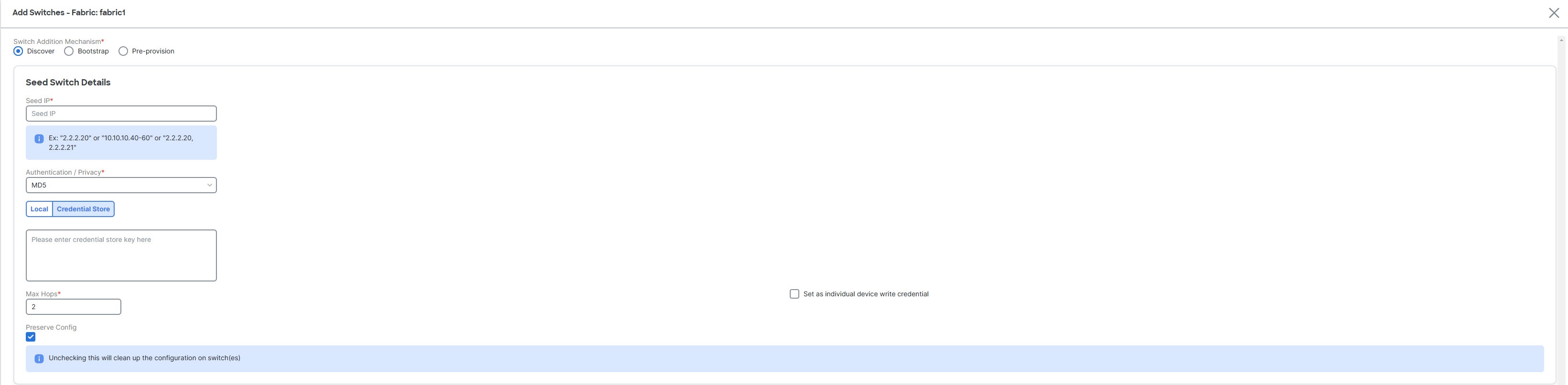
Enter the IP address in the Seed IP field.
-
The Authentication/Privacy field is selected by default.
-
If you haven’t configured credential store, in the Local tab, enter the Username and Password of the switch.
-
If you have configured credential store, in the Credential Store tab, enter the credential store key.
You will see the Credential Store tab only if you configured system certificate and mapped to CyberArk feature. For more information on CA certificates and credential store, see Managing Certificates in your Nexus Dashboard and Configuring Users and Security.
-
Choose Set as individual device write credential check box to set Discovery/Read credentials as LAN/Write credential for individual devices.
-
The Max Hops field is set to 2 by default.
-
The Preserve Config check box is chosen by default.
Check the Preserve Config check box for a brownfield import of a device into the fabric. For a greenfield import where the device configuration will be cleaned up as a part of the import process, uncheck the Preserve Config check box.
Routed fabric does not support brownfield import of a device into the fabric.
-
Click Discover Switches.
The Add Switches page appears. Since the Max Hops field was populated with 2 (by default), the switch with the specified IP address (leaf-91) and switches two hops from that switch, are populated in the Add Switches result.
-
If Nexus Dashboard was able to perform a successful shallow discovery to a switch, the status column shows as Manageable. Choose the check box next to the appropriate switch(es) and click Add Switches.
Though this example describes the discovery of one switch, multiple switches can be discovered at once.
The switch discovery process is initiated. The Progress column displays progress for all the selected switches. It displays done for each switch on completion.
You must not close the screen (and try to add switches again) until all selected switches are imported or an error message comes up.
If an error message comes up, close the screen. The fabric topology screen comes up. The error messages are displayed at the top right part of the screen. Resolve the errors wherever applicable and initiate the import process again by clicking Add Switches in the Actions panel.
Nexus Dashboard discovers all the switches, and the Progress column displays done for all switches, close the screen. The Standalone fabric topology page comes up again. The switch icons of the added switches are displayed in it.
You will encounter the following errors during switch discovery sometimes.
-
Click Refresh topology to view the latest topology view.
When all switches are added and roles assigned to them, the fabric topology contains the switches and connections between them.
-
After discovering the devices, assign an appropriate role to each device. For more information on roles, see Assign switch roles.
If you choose the Hierarchical layout for display (in the Actions panel), the topology automatically gets aligned as per role assignment, with the leaf devices at the bottom, the spine devices connected on top of them, and the border devices at the top.
Assign vPC switch role - To designate a pair of switches as a vPC switch pair, right-click the switch and choose the vPC peer switch from the list of switches.
AAA server password - During fabric creation, if you have entered AAA server information (in the Manageability tab), you must update the AAA server password on each switch. Else, switch discovery fails.
When a new vPC pair is created and deployed successfully using Nexus Dashboard, one of the peers might be out-of-sync for the no ip redirects CLI even if the command exists on the switch. This out-of-sync is due to a delay on the switch to display the CLI in the running configuration, which causes a diff in the configuration compliance. Re-sync the switches in the Config Deployment page to resolve the diff.
-
Click Save.
The template and interface configurations form the underlay network configuration on the switches. Also, freeform CLIs that were entered as part of fabric settings (leaf and spine switch freeform configurations entered in the Advanced tab) are deployed.
Configuration Compliance: If the provisioned configurations and switch configurations do not match, the Status column displays out-of-sync. For example, if you enable a function on the switch manually through a CLI, then it results in a configuration mismatch.
To ensure configurations provisioned from Nexus Dashboard to the fabric are accurate or to detect any deviations (such as out-of-band changes), Nexus Dashboard’s Configuration Compliance engine reports and provides necessary remediation configurations.
When you click Deploy Config, the Config Deployment page appears.
If the status is out-of-sync, it suggests that there is inconsistency between Nexus Dashboard and configuration on the device.
The Re-sync button is displayed for each switch in the Re-sync column. Use this option to resynchronize Nexus Dashboard state when there is a large scale out-of-band change, or if configuration changes do not register in Nexus Dashboardproperly. The re-sync operation does a full CC run for the switch and recollects "show run" and "show run all" commands from the switch. When you initiate the re-sync process, a progress message is displayed on the screen. During the re-sync, the running configuration is taken from the switch. The Out-of-Sync/In-Sync status for the switch is recalculated based on the intent defined in Nexus Dashboard.
Click the Preview Config column entry (updated with a specific number of lines). The Config Preview page comes up.
The Pending Config tab displays the pending configurations for successful deployment.
The Side-by-side Comparison tab displays the current configurations and expected configurations together.
Multi-line banner motd configuration can be configured in Nexus Dashboard with freeform configuration policy, either per switch using switch_freeform, or per fabric using leaf/spine freeform configuration. Note that after the multi-line banner motd is configured, deploy the policy by executing the Deploy Config option in the (top right part of the) fabric topology screen. Else, the policy may not be deployed properly on the switch. The banner policy is only to configure single-line banner configuration. Also, you can only create one banner related freeform configuration/policy. Multiple policies for configuring banner motd are not supported.
-
Close the page.
After successful configuration provisioning (when all switches display a progress of 100%), close the screen.
The fabric topology is displayed. The switch icons turn green to indicate successful configuration.
If a switch icon is in red color, it indicates that the switch and Nexus Dashboard configurations are not in sync. When deployment is pending on a switch, the switch is displayed in blue color. The pending state indicates that there is a pending deployment or pending recomputation. You can click on the switch and review the pending deployments using the Preview or Deploy Config options, or click Deploy Config to recompute the state of the switch.
If there are any warning or errors in the CLI execution, a notification appears on the Fabric builder page. Warnings or errors that are auto-resolvable have the Resolve option.
An example of the Deploy Config option usage is for switch-level freeform configurations.
Add Cisco Nexus 9800 series switches to a fabric
These sections provide information about adding Cisco Nexus 9800 series switches to a fabric:
For information on how to add switches to a fabric, see Add switches to a fabric.
Supported roles for Cisco Nexus 9800 series switches by fabric type
Nexus Dashboard supports all border and border gateway roles for Cisco Nexus 9800 series switches.
| Fabric Type | Roles |
|---|---|
|
Data Center VXLAN EVPN Fabric |
Border Gateway, Spine, Super Spine, Border Gateway Spine, Border Gateway Super Spine, Border, Border Spine, Border Super Spine |
|
BGP Fabric |
Spine, Border, Border Gateway, Border Gateway Spine, Super Spine, Border Super Spine, Border Gateway Super Spine |
|
Campus VXLAN EVPN Fabric |
Border Gateway Spine, Border Gateway Super Spine, Border Gateway |
Supported Cisco NX-OS release for Cisco Nexus 9800 series switches
Nexus Dashboard supports Cisco NX-OS release 10.4(3) only when adding Cisco Nexus 9800 series switches to a fabric as a border or a border gateway. Nexus Dashboard supports Cisco NX-OS release 10.4(2) and 10.4(3) when adding Cisco Nexus 9800 series switches to a fabric as a spine or a super spine.
Guidelines for adding Cisco Nexus 9800 series switches to a fabric
Cisco Nexus 9800 series switches support the following features:
-
VXLAN BGP EVPN MultiSite anycast border gateway
-
VXLAN BGP EVPN border spine
-
DCI: advertise primary IP address (PIP)
-
DCI: IR underlay with IPv4
-
Fabric: Ingress replication (IR) with an IPv4 underlay
-
Fabric: Ingress replication (IR) with an IPv6 underlay
-
Fabric: A multicast underlay with Protocol Independent Multicast (PIM) Any Source Multicast (ASM) IPv4
-
NGOAM
-
TRMv4
Limitations for adding Cisco Nexus 9800 series switches to a fabric
Cisco Nexus 9800 series switches do not support the following:
-
No support for a local Layer 2 host.
-
Cisco Nexus 9800 series switches support only Layer 3 VNI without VLAN configuration regardless of the value set for Enable L3VNI w/o VLAN as defined at the VRF level. For more information, see the section "Layer 3 VNI Without VLAN" in Editing Data Center VXLAN Fabric Settings.
-
Layer 2 stretching for a VXLAN EVPN Multi-Site fabric requires a network attachment on the BGW.
-
No blocking support when you try to attach a network on the Cisco Nexus 9800 series switch when you select a local port.
-
No SVI is generated on the Cisco Nexus 9800 series switch on the VRF or network attachment.
-
No support for the aggregation role, so there is no support for a Cisco Nexus 9800 series switch as an aggregation device.
-
No support for ToR or leaf.
-
No support for CloudSec.
-
No support for a vPC.
-
No support for TRMv6.
Add switches using the bootstrap mechanism
When a new Cisco NX-OS device is powered on, typically that device has no startup configuration or any configuration state. Consequently, it powers on with NX-OS and goes into a POAP loop after the initialization. The device then sends out DHCP requests on all the interfaces that are up, including the mgmt0 interface.
POAP access user validated key exchange and password-less ssh to limit configuration file access to the specific switch for a finite time. Therefore, you must accept a new key via Add Switches > Bootstrap whenever a device attempts POAP.
If there is IP reachability between the device and Nexus Dashboard, the DHCP request from the device is forwarded to Nexus Dashboard. For easy day-0 device bring-up, you should enable the bootstrap options in Fabric settings.
With bootstrap enabled for the fabric, the DHCP request coming from the device will be serviced by Nexus Dashboard. The temporary IP address allocated to the device by Nexus Dashboard will be employed to learn basic information about the switch, including the device model, device NX-OS version, and so on.
-
Click Manage > Fabrics.
-
Click a supported fabric type.
The Fabric: fabric-name page appears.
-
Click Inventory > Switches.
-
Click Actions > Add Switches.
The Add Switches - Fabric: fabric-name page appears.
-
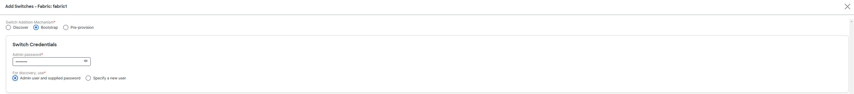
Click the Bootstrap radio button.
-
Enter the admin password in the Admin password field in the Switch Credentials area of the page.
-
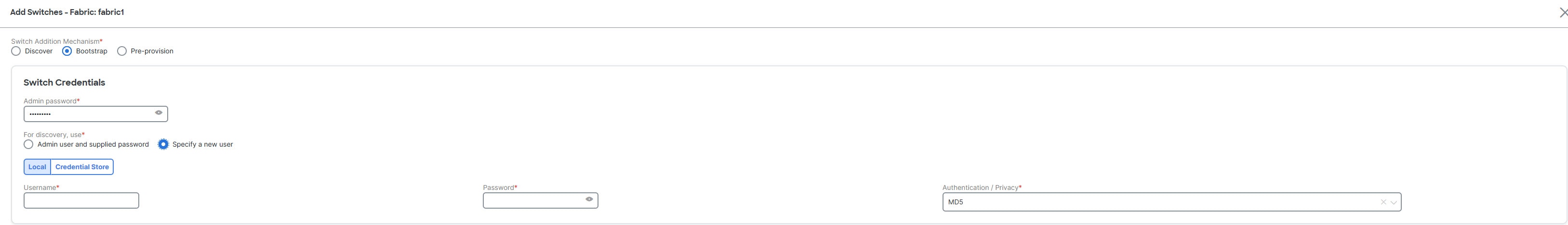
Choose one of the discovery options, Admin user and supplied password or Specify a new user.
-
If you choose Specify a new user, you will see Local and Credential Store tabs.
-
If you haven’t configured credential store, in the Local tab, enter the Username, Password, and Authentication/Privacy details of the switch.
-
If you have configured credential store, in the Credential Store tab, enter the credential store key and authentication/privacy key.
You will see the Credential Store tab only if you configured system certificate and mapped to CyberArk feature. For more information on CA certificates and credential store, see Managing Certificates in your Nexus Dashboard and Configuring Users and Security.
-
You can add switches one at a time using the Add option or add multiple switches at the same time using the Import option.
If you use the Add option, ensure you enter all the required details.
It might take some time for the switches to appear.
-
Choose a required switch.
-
Click Edit.
The Edit bootstrap switch dialog appears.
-
Enter the required details.
-
Click Save.
-
Choose the switch.
-
Click Import Selected Switches.
Return Material Authorization (RMA)
This section describes how to replace a physical switch in a fabric.
Prerequisites
-
Ensure that the fabric is up and running with minimal disruption while replacing the switch.
-
To use the POAP/PnP RMA flow, configure the fabric for bootstrap.
-
Perform Recalculate and deploy more than once, if needed, to copy the FEX configurations for the RMA of switches that have FEX deployed.
Guidelines and limitations for RMA
-
Nexus Dashboard supports the RMA feature on Catalyst 9000 series of switches. However, the feature is not supported on Catalyst switches with Stackwise or Stackwise Virtual.
-
When GIR is enabled before upgrading the Cisco Nexus 7000 Series switches, Nexus Dashboard pushes the system mode maintenance command to the switches when RMA is initiated. This command applies the configuration that is present in the default maintenance mode profile to the switches. For more information on performing Graceful Insertion and Removal (GIR) on the Cisco Nexus 7000 Series switches, see Configuring GIR.
-
When replacing a switch, ensure that the replacement switch is of the same model as the original device. If there is a mismatch, Nexus Dashboard generates a warning message indicating the mismatch.
-
With Nexus Dashboard integration with Nexus Dashboard Orchestrator, after the RMA of the switches into Nexus Dashboard, you need to perform a manual import of your networks and VRFs on Nexus Dashboard Orchestrator to view the diff of the schema on Nexus Dashboard. After performing the RMA on Nexus Dashboard, Nexus Dashboard Orchestrator sees a change of the serial number after a refresh on the Nexus Dashboard Orchestrator fabric. Nexus Dashboard requires a reimport of the switch for the serial number to be in sync.
Provision RMA with POAP/PnP
-
Navigate to the Fabric Overview page.
-
Move the device into maintenance mode. To move a device into maintenance mode,
-
Select the device, choose Actions > More > Change Mode.
-
From the Mode drop-down list, choose Maintenance.
-
Click Save and Deploy Now.
-
-
Power down the device before removing the device from the network.
-
Physically replace the device in the network. All the connections should be made in the same place on the replacement device as they existed on the original device.
-
Power on the device and onboard the device using POAP/PnP.
-
Select the RMA device and choose Actions > More > Provision RMA.
The RMA flow is initiated.
-
Enter the admin password in the Admin password field and click Provision RMA.
(Optional) You can set a AAA user name and password for discovery.
-
Select the replacement device and choose Actions > More > Provision RMA.
-
Enter the admin password in the Admin password field and click Provision RMA.
Provision RMA manually
Follow these steps when the bootstrap process is not possible or not desired to replace a faulty switch manually.
-
Place the device in maintenance mode (optional).
-
Power down the faulty device before removing it from the network.
-
Physically disconnect the faulty switch from the fabric.
-
Identify all the connections of the faulty switch to ensure the replacement switch uses the same interfaces.
-
Obtain the replacement switch.
-
Connect the replacement switch cables to the fabric using the same interfaces as the faulty switch (e.g., if switch-1 eth1/1 is connected to spine-1 eth1/1, connect switch-2 to the same interface).
-
Power on the replacement switch and connect to its console.
-
Log in to the replacement switch through the console and configure these basic settings.
-
Set the hostname.
-
Configure the mgmt0 IP address.
-
Configure AAA commands, if AAA is used.
-
-
Update LAN and discovery credentials in Nexus Dashboard for the newly configured AAA user, if applicable.
-
Go to Discovery > Rediscover to rediscover the replacement switch in Nexus Dashboard.
Nexus Dashboard detects the change in serial number and updates the UI with the new serial number of the replacement switch.
-
Navigate to Actions > Deploy to deploy the expected configuration.
If breakout ports or FEX ports are in use, deploy again to fully restore the configuration.
-
After a successful deployment and when the device status shows In-Sync, move the device back to normal mode.
-
If AAA is used, click Recalculate and Deploy to verify that the fabric remains in sync.
RMA for user with local authentication
This task is only applicable to non-POAP switches.
Use these steps to perform RMA for a user with local authentication:
-
After the new switch comes online, SSH into the switch and reset the local user password with the cleartext password using the username command. Reset the local user password to resync the SNMP password. The password is stored in the configuration file in a nontransferable form.
-
Wait for RMA to complete.
Pre-provisioning a device
Nexus Dashboard supports provisioning of device configurations in advance. This is specifically applicable for scenarios where devices have been procured, but not yet delivered or received by the customers. The purchase order typically has information about the device serial number, device model, and so on, which in turn can be used to prepare the device configuration in Nexus Dashboard prior to the device connectivity to the network.
Pre-provisioning is supported for Cisco NX-OS devices in fabric types:
-
Data Center VXLAN EVPN
-
Campus VXLAN EVPN
-
Enhanced Classic LAN
-
Legacy Classic LAN
-
AI
-
External and Inter-Fabric Connectivity
-
IP Fabric for Media
Pre-provision a device
You can provision devices before adding them to a fabric.
Before you begin
-
Ensure that you check the Enable Bootstrap check box on the Edit Fabric Settings > Fabric Management > Bootstrap tab.
-
Ensure that you check the Enable Local DHCP Server check box.
Guidelines and limitations for pre-provisioning a device
The pre-provisioned devices support the following configurations in Nexus Dashboard:
-
Base management
-
vPC pairing
-
Intra-fabric links
-
Ethernet ports
-
Port-channel
-
vPC
-
ST FEX
-
AA FEX
-
Loopback
-
Overlay network configurations
The pre-provisioned devices do not support the following configurations in Nexus Dashboard:
-
Inter-fabric links
-
Sub-interface
-
Interface breakout configuration
When Nexus Dashboard pre-provisions a device that has breakout links, you need to specify the corresponding breakout command along with the device model and gateway in the Data field in the Add a new device to pre-provisioning page to generate the breakout Policy Template Instance (PTI).
The interface breakout CLI in the Data key of the pre-provision payload must contain the exact format as is on the show running-configuration output from the switch. You can separate multiple breakout commands with a semicolon (;).
This table describes the definitions of the fields in the Data JSON object.
|
Field |
Description |
|
modulesModel |
(Mandatory) Specifies the switch module’s model information. |
|
gateway |
(Mandatory) Specifies the default gateway for the management VRF on the switch. This field is required to create the intent to pre-provision devices. You must enter the gateway even if it is in the same subnet as Nexus Dashboard to create the intent as part of pre-provisioning a device. |
|
breakout |
(Optional) Specifies the breakout command provided on the switch. |
|
portMod |
(Optional) Specifies the port mode of the breakout interface. |
Configure pre-provisioning of a device
-
Click Manage > Fabrics.
-
Click a supported fabric type.
The Fabric: fabric-name page appears.
-
Click Inventory > Switches.
-
Click Actions > Add Switches.
The Add Switches - Fabric: fabric-name page appears.
-
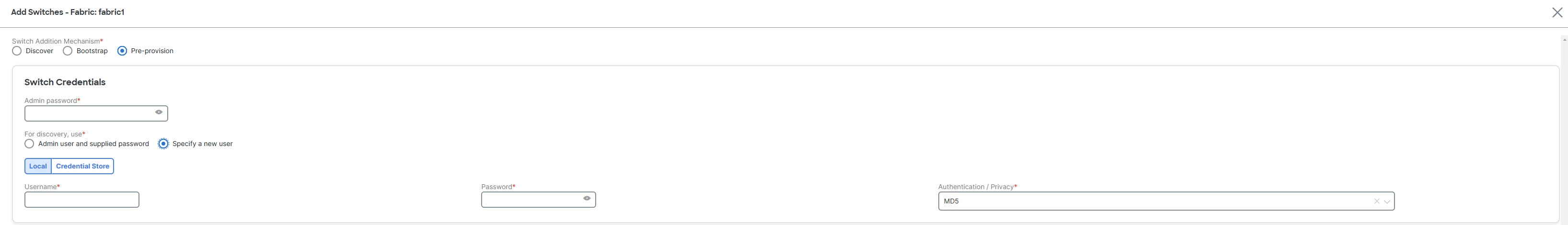
Click the Pre-provision radio button.
-
Enter the admin password in the Admin password field in the Switch Credentials area of the page.
-
Choose one of the discovery options, Admin user and supplied password or Specify a new user.
-
If you choose Specify a new user, you will see Local and Credential Store tabs.
-
If you haven’t configured credential store, in the Local tab, enter the Username, Password, and Authentication/Privacy details of the switch.
-
If you have configured credential store, in the Credential Store tab, enter the credential store key and authentication/privacy key.
You will see the Credential Store tab only if you configured system certificate and mapped to CyberArk feature. For more information on CA certificates and credential store, see Managing Certificates in your Nexus Dashboard and Configuring Users and Security.
-
-
Click Actions > Add in the Switches to Pre-provision area of the page.
The Pre-provision a switch dialog box appears.
-
Enter the required fields as described in this table.
Field
Description
Serial Number
Specifies the serial number of the switch.
Model
Specifies the model number of the switch. Choose a predefined list of device models from the drop-down list or enter the model number of the switch.
Version
Specifies the version number of the switch.
IP Address
Specifies the IP address of the switch.
Hostname
Specifies the hostname of the switch.
Image Policy
Specifies an image policy from the drop-down list.
Switch Role
Specifies the switch role from the drop-down list.
Gateway
Specifies the gateway IP address.
Data
Specifies the data value for the JSON object.
Example values:
-
{"modulesModel": ["N9K-C93180LC-EX"], "gateway": "10.1.1.1/24"}
-
{"modulesModel": ["N9K-C93180LC-EX"],"breakout": "interface breakout module 1 port 1 map 10g-4x", "portMode": "hardware profile portmode 4x100G+28x40G", "gateway": "172.22.31.1/24" }
-
{"modulesModel": ["N9K-X9736C-EX", "N9K-X9732C-FX", "N9K-C9516-FM-E2", "N9K-C9516-FM-E2", "N9K-C9516-FM-E2", "N9K-C9516-FM-E2", "N9K-SUP-B+", "N9K-SC-A", "N9K-SC-A"], "gateway": "172.22.31.1/24"}
-
{"breakout":"interface breakout module 1 port 50 map 10g-4x" , "gateway": "172.16.1.1/24", "modulesModel": ["N9K-C93180YC-EX "]}
-
{"modulesModel": ["N9K-X9732C-EX", "N9K-X9732C-EX", "N9K-C9504-FM-E", "N9K-C9504-FM-E", "N9K-SUP-B", "N9K-SC-A", "N9K-SC-A"], "gateway": "172.29.171.1/24", "breakout":"interface breakout module 1 port 1,11,19 map 10g-4x; interface breakout module 1 port 7 map 25g-4x"}
-
{"modulesModel": ["N9K-C93180LC-EX"], "gateway": "10.1.1.1/24","breakout": "interface breakout module 1 port 1-4 map 10g-4x","portMode": "hardware profile portmode 48x25G + 2x100G + 4x40G"}
-
-
Click Save.
-
Click Actions > Add to add the switch.
You can add switches one at a time using the Add option or add multiple switches at the same time using the Import option.
If you use the Actions > Add option, ensure you enter all the required details on the Pre-provision a switch dialog box.
-
Click Save.
Nexus Dashboard adds the pre-provisioned switch.
To bring in the physical device, you can follow the manual RMA or PowerOn Auto Provisioning (POAP) RMA procedure.
For more information, see Return Material Authorization (RMA). If you use the POAP RMA procedure, ignore the error message of failing to put the device into maintenance mode due to no connectivity, since it is expected to have no connectivity to a non-existing device.
Automatically import a pre-provisioned device using POAP
You can automatically import a pre-provisioned device to a fabric. If you enable the Auto admit pre-provisioned switches during re-poap option on the Admin > System Settings > Fabric management > Switch bootstrap dashlet, Nexus Dashboard automatically imports the pre-provisioned device to the fabric using PowerOn Auto Provisioning (POAP). You can avoid having to reenter a username, password, and bootstrap parameters on the Add Switches (Bootstrap) page.
For example, you might need to pre-provision a test device before you receive the actual device, and later replace the test device with the actual device.
Configure automatic import of a pre-provisioned device
-
Navigate to the Admin > System Settings > Fabric management > Switch bootstrap dashlet.
-
Check the Auto admit pre-provisioned switches during re-poap check box.
By default, the Auto admin pre-provisioned switches during re-poap option is not enabled.
-
Click Save.
-
Navigate to Manage > Fabrics.
-
Click a supported fabric type.
The Fabric Overview page appears.
-
Click Actions > Edit fabric settings.
-
Click the Fabric management tab and then the Bootstrap tab.
-
Check the Enable Bootstrap check box.
-
Check the Enable Local DHCP Server check box.
-
Enter values for the DHCP Scope Start Address, DHCP Scope End Address, and the Switch Mgmt Default Gateway fields.
-
Click Save.
-
Follow the steps for adding a switch in Pre-provision a device.
-
Click Import Selected Switches.
Nexus Dashboard automatically saves the entry for this device and later Nexus Dashboard adds the device to the fabric.
Nexus Dashboard automatically imports the pre-provisioned device to the fabric and the Import Selected Switches option is no longer editable.
On the Fabric Overview > Inventory > Switches page, the status of the switch changes from Unreachable to Ok for the selected device.
Pre-provision an Ethernet interface
Before you begin
Make sure that you have a pre-provisioned device in your fabric. For more information, see Pre-provision a device.
You can pre-provision Ethernet interfaces on the Manage > Fabrics > Connectivity > Interfaces page. This pre-provisioning feature is supported in the Easy, External and Inter-Fabric Connectivity, and Routed fabrics. You can add Ethernet interfaces to only pre-provisioned devices before they are discovered in Nexus Dashboard.
Before attaching a network and a VRF, you must pre-provision the Ethernet interface before adding it to port channels, vPCs, ST FEX, AA FEX, loopback, subinterface, tunnel, ethernet, and SVI configurations.
-
Click on the fabric containing the pre-provisioned device from the Manage > Fabrics page.
The Fabric Overview page appears.
-
Navigate to Connectivity > Interfaces.
-
On the Interfaces tab, click Actions > Create interface.
The Create interface page appears.
-
Enter all the required details on the Create interface page.
Field
Description
Type
Select Ethernet from the drop-down list.
Select a device
Select the pre-provisioned device.
Interface Name
Enter a valid interface name based on the module type. For example, Ethernet1/1, eth1/1, or e1/1. The interface with the same name should be available on the device after it is added.
Policy
Select a policy that should be applied on the interface.
You cannot add an Ethernet interface to an already managed device.
-
Click Save.
-
Click Preview to check the expected configuration that will be deployed to the switch after it is added.
The Deploy button is disabled for Ethernet interfaces since the devices are pre-provisioned.
Pre-provision a vPC pair
Before you begin
Ensure that you have enabled Bootstrap in fabric settings.
-
Import both the devices into the fabric. For more information, refer Pre-provision a device.
Two Cisco Nexus 9000 series devices that are pre-provisioned are added to an existing fabric.
-
Choose Add Switches from the Actions drop-down list.
-
On the Inventory Management page, click PowerOn Auto Provisioning (POAP).
The devices show up in the fabric as gray or undiscovered devices.
-
Right click and select appropriate roles for these devices similar to other reachable devices.
-
To create vPC pairing between the devices with physical peer-link or MCT, perform the following steps:
-
Provision the physical Ethernet interfaces that form the peer-link.
The vPC peer-link between leaf1-leaf2 comprises of interfaces Ethernet1/44-45 on each device.
-
-
Choose Manage > Fabrics > Connectivity > Interfaces to pre-provision ethernet interfaces.
For more information, see Pre-provision an Ethernet interface.
-
Create a pre-provisioned link between these interfaces.
On the Links tab, click on Actions > Create.
Create two links, one for leaf1-Ethernet1/44 to leaf2-Ethernet1/44 and another one for leaf1-Ethernet1/45 to leaf2-Ethernet1/45.
Ensure that you choose int_pre_provision_intra_fabric_link as link template. The Source Interface and Destination Interface field names, must match with the Ethernet interfaces pre-provisioned in the previous step.
After the links are created, they are listed on the Links tab.
-
On the Topology page, right click on a switch and choose vPC Pairing from the drop-down list.
Select the vPC pair and click vPC pairing for the pre-provisionsed devices.
-
Click Recalculate & Deploy to generate the required intended vPC pairing configuration for the pre-provisioned devices.
After completion, the devices are correctly paired and the vPC pairing intent is generated for the devices and the policies are generated.
-
Because the devices are not yet operational, Configuration Compliance (CC) does not return an IN-SYNC or OUT-OF-SYNC status for these devices.
This is expected as CC requires the running configuration from the devices in order to compare that with the intent and calculate and report the compliance status.
Pre-provision a vPC host interface
-
Create physical Ethernet interfaces on the pre-provisioned devices.
-
Add a vPC host interface similar to a regular vPC pair of switches. For more information, see Pre-provision an Ethernet interface.
For example,
leaf1-leaf2might represent a pre-provisioned vPC device pair, assuming that the Ethernet interface 1/1 is already pre-provisioned on both the leaf1 and leaf2 devices. -
Create a vPC host trunk interface.
Nexus Dashboard creates the vPC host interface and displays a status as Not discovered.
The Preview and Deploy actions won’t yield a result because both require the device to be present.
Attach overlays to pre-provisioned devices
You can attach overlay VRFs and networks to pre-provisioned devices similar to any other discovered device.
Nexus Dashboard attaches an overlay network to the pre-provisioned vPC pair of leafs (leaf1-leaf2). Nexus Dashboard also attaches the overlay network to the pre-provisioned vPC host interface port-channels created on leaf1-leaf2.
Preview and Deploy operations are disabled for the pre-provisioned devices, because the devices are not reachable. After the pre-provisioned device is reachable, all operations are enabled similar to other discovered devices.
-
On the Fabric Overview page, click the Configuration Policies tab and choose Actions > Edit policy.
-
View the entire intent generated for the pre-provisioned device, including the overlay network and VRF attachment information. For more information on configuration policies, see Working with Configuration Policies for Your Nexus Dashboard LAN or IPFM Fabrics.
Preview switches
-
Navigate to the Inventory page.
For more information, see Navigate to the Inventory page.
The Switches tab displays by default.
-
Click a switch to bring up the Switch Overview page.
-
Add the necessary switches.
For more information, see Add switches to a fabric.
After adding the switches, you can preview the switches with pending configurations, the side-by-side comparison of running configurations, and the expected configurations for the switches. You can select multiple switches and preview them at the same instance. The Preview page displays the pending configurations for the successful deployment of a switch.
To preview the switches and resync the ones with pending configurations, perform these steps:
-
On the Switches page, use the check boxes next to the switches to choose the switches that you want to preview.
-
From the Actions drop-down list, choose Preview.
The Preview Config page appears. This page displays the switch configuration information, such as the switch name; its ip address, role, serial number; the fabric status—whether it is in sync, out of sync, or not available; the pending configuration; the status description; and the progress.
-
You can also preview switches from the Switch Overview page using Actions > Preview.
-
To only preview the configuration, view the displayed information and click Close.
-
To resynchronize the switches with pending configuration, click Resync. The progress bar displays the progress of the resynchronization.
-
Click Close to close the Preview Config page.
-
To view the pending configurations and side-by-side comparison, click the respective link in the Pending Config column.
Alternatively, on the Fabric Overview > Actions drop-down list, choose Recalculate and deploy.
The Deploy Configuration page appears. It displays the configuration status on the switches. You can also view the pending configurations by clicking the respective link in the Pending Config column.
The Pending Config page appears.
The Pending Config tab on this page displays the pending configurations on the switch.
The Side-by-Side Comparison tab displays the running configuration and expected configuration in a side-by-side representation.
-
Close the Pending Config page.
Deploy configuration
This deploy option is a local operation for a switch, that is, the expected configuration or intent for a switch is evaluated against its current running configuration. Nexus Dashboard performs a configuration compliance check for the switch to get the In-Sync or Out-of-Sync status. If the switch is out of sync, the user is provided with a preview of all the configurations running in that particular switch that vary from the intent defined by the user for the respective switch.
-
Choose the required switch.
-
Choose Actions > Deploy to deploy the configuration on a switch.
The Deploy Configuration page appears.
-
Click Resync to synchronize the configuration.
-
Click Deploy.
The Status column displays a FAILED or a SUCCESS state. For a FAILED status, investigate the reason for the failure to address the issue.
Fabrics that have VXLANv6 with multicast replication mode configuration require VTEPs and route reflectors that are running on release 10.4(2) or later. If you have a switch that is running on a release earlier than 10.4(2) and you attempt to add that switch to this type of fabric, you might see this error message when you try to deploy that configuration:
command send-community both is invalid
That error message appears because you attempted to add a switch running on a release earlier than 10.4(2) to this sort of fabric.
-
Click Close to navigate to the switch page.
Discovery
This chapter contains below sections:
Update credentials
Use update discovery credentials for updating discovered switches.
-
Choose the required switch and choose Actions > Discovery > Update Credentials.
The Update Discovery Credentials page appears.
-
On the Update Discovery Credentials page, enter the discovery credentials such as discovery username and password.
-
Click Update to save the discovery credentials.
If you do not provide the discovery credentials, Nexus Dashboard uses the admin user and password to discover the switches.
Rediscover
You can rediscover switch and check the status of it.
To rediscover the switch:
-
Choose required switch, choose Actions > Discovery > Rediscover to rediscover switches.
The Discovery Status column shows the status as Rediscovering and after discovering it displays the status.
Guidelines and limitations for changing discovery IP address
You can change the discovery IP address of a device that exists in a fabric.
The following are the guidelines and limitations for changing the discovery IP address.
-
Changing discovery IP address is supported for NX-OS switches and devices that are discovered over their management interface.
-
Changing discovery IP address is supported for templates such as:
-
Data Center VXLAN EVPN
-
Routed fabric
-
External and Inter-Fabric Connectivity
-
Classic LAN
-
-
Changing discovery IP address is supported in both managed and monitored modes.
-
Only users with the network-admin role can change the discovery IP address on Nexus Dashboard.
-
The discovery IP address must not be used on other devices, and it must be reachable when the change is done.
-
While changing the discovery IP address for a device in a managed fabric, switches are placed in migration mode.
-
When you change the IP address of a switch that is linked to a vPC peer, corresponding changes such as vPC peer and domain configuration are updated accordingly.
-
Nexus Dashboard restores the original IP address. Nexus Dashboard reports an out-of-sync status post restore. Configuration intent for the device must be updated manually to get the in-sync status.
-
Nexus Dashboard restores the original device discovery IP and reports the switch as unreachable post restore.
-
Device alarms associated with the original discovery IP address are purged after the change of IP address.
Change discovery IP address
You must make the management IP address and route-related changes on the device and ensure the reachability of the device from Nexus Dashboard.
To change the discovery IP address from the Nexus Dashboard Web UI, perform these steps:
-
Navigate to the Inventory page.
For more information, see Navigate to the Inventory page.
-
On the Switches tab, click the Refresh icon adjacent to the Action button on the main page.
A switch with a changed IP address displays with the Unreachable state in the Discovery Status column.
-
Click the check box next to the Switch column and choose the switch.
You can change the IP address for an individual switch, but not for multiple switches.
-
Choose Actions > Discovery > Change Discovery IP on the Switches tab.
The Change Discovery IP dialog box appears.
-
Enter the appropriate IP address in the New IP Address text field and click OK.
-
The new IP address must be reachable from Nexus Dashboard to update successfully.
-
Repeat the above procedures for the devices where the discovery IP address must be changed before proceeding with further steps.
-
If the fabric is in managed mode, the device mode is updated to migration mode.
-
-
From the Fabric Overview > Actions drop-down list, click Recalculate and deploy to initiate the process of updating Nexus Dashboard configuration intent for the devices. Similarly, you can recalculate the configuration on the Topology page.
-
Choose View in topology to navigate to the Topology page.
-
Right-click on the switch and click Deploy Config.
The Nexus Dashboard configuration intent for the device management related configuration is updated and the device mode status for the switch is changed to normal mode. The switch configuration status is displayed as In-Sync.
The Performance Manager (PM) records associated with the old switch IP address are purged and new record collections take an hour to initiate after the changes.
Update VRF
To update discovery VRF for switches, perform the following steps:
If you enable update VRF option, the VRF associated with the interface which has discovery IP address for a switch will be auto discovered in Nexus Dashboard during importing a switch. You can override VRF settings for required switch with appropriate user role.
-
Choose required switch, choose Actions > Discovery > Update VRF.
The Update Discovery VRF window appears.
-
In the Update Discovery VRF window, choose New VRF and Interface from drop-down list.
-
Click OK to save new VRF details.
Clear SSH host keys
Nexus Dashboard enforces SSH host key verification by default starting from 4.1.1. It supports all SSH key types supported by data center devices, including those supported by NX-OS and ACI switches. SSH host keys are sticky, i.e., once a key is seen, it gets attached to that device permanently. A new key coming from a device indicates that the key was changed without the knowledge of Nexus Dashboard. This is what causes switch discovery state transitioning to "SSH Host Key Mismatch". This may point to a spoofing attempt or a genuine situation, such as an out-of-band switch write-erase, reload, or clear ssh keys command executed directly on the device CLI prompt.
When a device goes into the state where it indicates a SSH Host Key Mismatch discovery status, you are advised to verify the key and ensure the key change is genuine, i.e., not an effect of a spoofing attempt. Once the key change is found to be genuine, you can clear the sticky key for the device using the Action > Discovery > Clear SSH Host keys option on the switches page in the Nexus Dashboard UI.
Follow these steps to clear the SSH host keys.
-
On the Nexus Dashboard UI, choose Manage > Inventory.
-
Choose the switch(es) for which you want to clear the SSH host keys.
-
Choose Switch Actions > Discovery > Clear SSH Host keys.
The Clear SSH Host keys action causes flushing of the SSH host keys associated with the chosen devices and appropriate confirmation notifications are displayed on the page.
-
Choose the switches with
SSH Host Key Mismatchstate from the switches table and choose Switch Action > Discovery > Rediscover
System-wide SSH Host Key clearing
Admin > System Settings > Fabric management > SSH tab provides an option to toggle the enable or disable SSH host key verification on Nexus Dashboard. Any state change of this toggle results in flushing of all SSH host keys learnt by Nexus Dashboard. A system wide flushing of SSH host keys may be done to clear large number of key mismatch situations or simply restarting the SSH host key learning on Nexus Dashboard, for example, after performing a large maintenance in the data center.
Discovery status
This table describes the switch discovery status string and its description.
| Type | Discovery status string | Description |
|---|---|---|
|
Discovery |
Discovering |
Switch is undergoing discovery, applicable for initial discovery |
|
Discovery |
Ok |
Switch is in a good state |
|
Discovery |
Rediscovering |
Switch is undergoing re-discovery |
|
Discovery |
Device Is Shutting Down |
Switch is shutting down |
|
Discovery |
Unreachable |
Switch IP is not pingable |
|
Discovery |
IP Address Change |
Switch IP update in progress |
|
Discovery |
Switch Key Mismatch |
Switch RMA in progress |
|
Discovery |
Discovery Timeout |
Switch discovery did not complete within the set discovery timeout (default: 5 minutes) |
|
Discovery |
Session Error (Code:100). Retrying. |
Discovery failed since sim-master service returned internal server error |
|
Discovery |
Session Error (Code:101). Retrying. |
Discovery failed since sim-master service is not ready |
|
Discovery |
Session Error (Code:102). Retrying. |
Discovery failed since sim-master service restarted while executing job |
|
Discovery |
Session Error (Code:103). Retrying. |
Discovery failed since sim-master service is not reachable |
|
Discovery |
Session Error (Code:104). Retrying. |
Discovery failed since sim-agent service restarted |
|
Discovery |
Session Error (Code:105). Retrying. |
Discovery failed since config-template service is not ready |
|
Discovery |
Session Error (Code:106). Retrying. |
Discovery failed since lan discovery credential is not found |
|
Discovery |
SSH Session Error |
Discovery failed since sim-agent encountered an SSH session error (or) HTTP timeout |
|
SNMP |
Unknown User Or Password |
SNMP username and/or password is incorrect |
|
SNMP |
Timeout |
SNMP returns timeout (default: 10 seconds) |
|
SNMP |
IP Connection Failed |
SNMP ConnectException encountered during session creation |
|
SNMP |
IP SNMP Socket Timeout |
SNMP SocketTimeoutException encountered during session creation |
|
SNMP |
IP GetSocket Failed |
SNMP IOException encountered during session creation |
Assign switch roles
You can assign roles to switches on Nexus Dashboard.
-
Choose the required switch and choose Actions > Set Role.
The Select Role page appears.
-
You can choose the required role and click Select.
A confirmation page appears.
You must rediscover the switch to view the status of new role assignments in the Role Status column.
The following roles are supported in Nexus Dashboard:
| Switch Role | Description |
|---|---|
|
Spine |
Spine switches provide Layer-3 underlay inter-connection between leaf switches as well as BGP EVPN control plane functions. They form the backbone of the network and connect to leaf switches, but not directly to each other. This design helps minimize latency and ensures a more predictable and consistent performance across the network. The Cisco Nexus 9000 series can act as spine and leaf switches, but choosing this switch depends on the specific model and network design requirements. |
|
Leaf |
A Virtual Tunnel Endpoint (VTEP) for providing Layer-2 / Layer-3 connectivity point for workloads and Layer 4 to Layer 7 services. Leaf switches connect directly to servers and storage devices within the data center. In a spine-and-leaf setup, every leaf switch is connected to every spine switch, ensuring multiple paths for data to travel. Leaf switches provide VXLAN encapsulation and decapsulation and Anycast Gateway services. Endpoints can be connected using individual, port-channel or virtual port-vhannel interfaces. |
|
Border |
A VTEP acting as handoff point across VXLAN and IP domains. A border switch in a network typically refers to a device that connects the internal network to external networks. In data centers, this can mean connecting the internal fabric to external networks, such as other data centers, the internet, or enterprise networks. Typically used for VRF-LITE and MPLS North-to-South connectivity. Optionally, endpoints and Layer 4 to Layer 7 services can also be connected. |
|
Border spine |
Provides VXLAN VTEP and EVPN control-plane functions at the same time. Supports all functions that are natively provided by both a spine switch and a border switch. See the Support for super spine switch role for more information. |
|
Border gateway |
Border gateway generally refers to a router or switch that participates in routing protocols to manage data flow between different network domains. It plays a crucial role in determining the best path for data to travel. A border gateway provides the same function as a border but adds the ability to extend VXLAN tunnels to remote fabrics for interconnected VXLAN fabrics. Functions include VXLAN packet re-origination and re-writes for Layer-2/Layer-3 extensions. Supported as Anycast or VPC. |
|
Border gateway spine |
Supports all functions that are natively provided by both a spine switch and a border gateway. Only Anycast border gateway is supported when merged with a spine switch. See the Support for super spine switch role for more information. |
|
Super spine |
A super spine is an additional layer of spine switches used in very large data center networks. This layer sits above the regular spine layer in a multi-tier architecture and acts as a backbone for connecting multiple spine-and-leaf pods, effectively interconnecting them to create a larger, cohesive network. A super spine connects multiple groups of spine and leaf switches within a single VXLAN fabric. It helps inter-connect multiple spine layers to achieve full CLOS architecture. When spine and super spine switches are present in the same fabric, the EVPN control-plane functions are handled at the super spine layer while the spine acts as a Layer-3 transit. |
|
Border super spine |
Supports all functions that are natively provided by both a border and a super spine. See the Support for super spine switch role for more information. |
|
Border gateway super spine |
Supports all functions that are natively provided by both a border gateway and a super spine. Only Anycast border gateway is supported when merged with a super spine. See the Support for super spine switch role for more information. |
|
Access |
The access switch is used at the bottom layer in a traditional three-tier network architecture. It serves as the entry point for hosts (VMs) and end devices such as computers, printers, and IP phones to connect to the network. It provides Layer-2 connectivity for workloads in Classic Ethernet networks. Endpoints can be connected using individual, port-channel or virtual port-channel interfaces. |
|
Aggregation |
The aggregation switches serve as an intermediary between the core network (which handles high-speed data transport) and the access layer. It consolidates data from multiple access switches before forwarding it to the core layer, reducing the number of direct connections to the core. It provides Layer-3 gateway and FHRP services in Classic Ethernet networks. Additional functions include connecting Layer 4 to Layer 7 services and external IP domains. |
|
Core router |
The core router is the topmost layer in a traditional three-tier network architecture. It provides fast and reliable data transport across the network, connecting different distribution (aggregation) layers and ensuring seamless communication between various parts of the network. The core layer is designed for high-speed data transmission, ensuring data can travel quickly and efficiently across the network. It provides Layer-3 external IP inter-connectivity (ISN) across different domains. Typically used as an EVPN route server in interconnected VXLAN fabrics or as an MPLS-P router. |
|
Edge router |
The edge router is a specialized router located at a network boundary that connects an internal network to external networks, such as the internet or a wide area network (WAN). Its primary role is to manage data traffic between the internal network and external networks, ensuring efficient and secure data flow. An edge router provides Layer-3 external IP inter-connectivity across different domains, such as VXLAN and Classic Ethernet networks. Common inter-connectivity includes VRF-Lite. |
|
Top of Rack (ToR) |
A ToR switch connects to the servers within the same rack through short, direct connections, which reduces cabling complexity and enhances performance. The ToR switch aggregates traffic from all the servers in the rack and uplinks it to higher-level switches or routers, such as spine switches in a spine-and-leaf architecture. A ToR switch provides Layer-2 only connectivity for endpoints. Endpoints can be connected using individual, port-channel or virtual port-channel interfaces. A ToR role is supported for both VXLAN and Classic LAN networks. For VXLAN-based fabrics, a ToR is connected to the leaf switch. |
You can change the switch role from an existing role to a supported role if there are no overlays on the switches. Click Recalculate and Deploy to generate the updated configuration. These changes are allowed for a switch role:
-
Leaf to Border
-
Border to Leaf
-
Leaf to Border Gateway
-
Border Gateway to Leaf
-
Border to Border Gateway
-
Border Gateway to Border
-
Spine to Border Spine
-
Border Spine to Spine
-
Spine to Border Gateway Spine
-
Border Gateway Spine to Spine
-
Border Spine to Border Gateway Spine
-
Border Gateway Spine to Border Spine
You cannot change the switch role from any leaf role to any spine role or from any spine role to any leaf role.
Support for super spine switch role
Super spine is a device that is used for interconnecting multiple spine-leaf PODs. You have an extra interconnectivity option with super spines. You can have multiple spine-leaf PODs within the same Easy fabric that are interconnected using super spines such that, the same IGP domain extends across all the PODs, including the super spines. Within such a deployment, the BGP RRs and RPs (if applicable) are provisioned on the super spine layer. The spine layer becomes a pseudo interconnect between the leafs and super spines. VTEPs may be optionally hosted on the super spines if they have the border functionality.
The following super spine switch roles are supported in Nexus Dashboard:
-
Super Spine
-
Border Super Spine
-
Border Gateway Super Spine
A border super spine handles multiple functionalities including the functionalities of a super spine, RR, RP (optionally), and a border leaf. Similarly, a border gateway super spine serves a super spine, RR, RP (optional), and a border gateway. It is not recommended to overload border functionality on the super spine or RR layer. Instead, attach border leafs or border gateways to the super spine layer for external connectivity. The super spine layer serves as the interconnect with the RR or RP functionality.
The following are the characteristics of super spine switch roles in Nexus Dashboard:
-
Supported with Easy fabrics only.
-
The Super Spine switch role and Border Super Spine switch role are also supported with the eBGP routed fabrics for IPv6 underlay using the Routed fabric template.
-
Can only connect to spines and borders.
The valid connections are:
-
Spines to super spines
-
Spines to border super spines and border gateway super spines
-
Super spines to border leafs and border gateway leafs.
-
RR or RP (if applicable) functionality is always be configured on super spines if they are present in a fabric. The maximum number of 4 RRs and RPs are supported even with Super Spines.
-
Border Super Spine and Border Gateway Super Spine roles are supported for inter-fabric connections.
-
vPC configurations aren’t supported on super spines.
-
Super spines don’t support IPv6 underlay configuration.
-
During the Brownfield import of switches, if a switch has the super spine role, the following error is displayed:
Serial number: [super spine/border super spine/border gateway superspine] role isn’t supported with the preserved configuration yes option.
-
Supported topologies for super spine switches
Nexus Dashboard supports the following topologies with super spine switches.
Topology 1: Super spine switches in a spine leaf topology
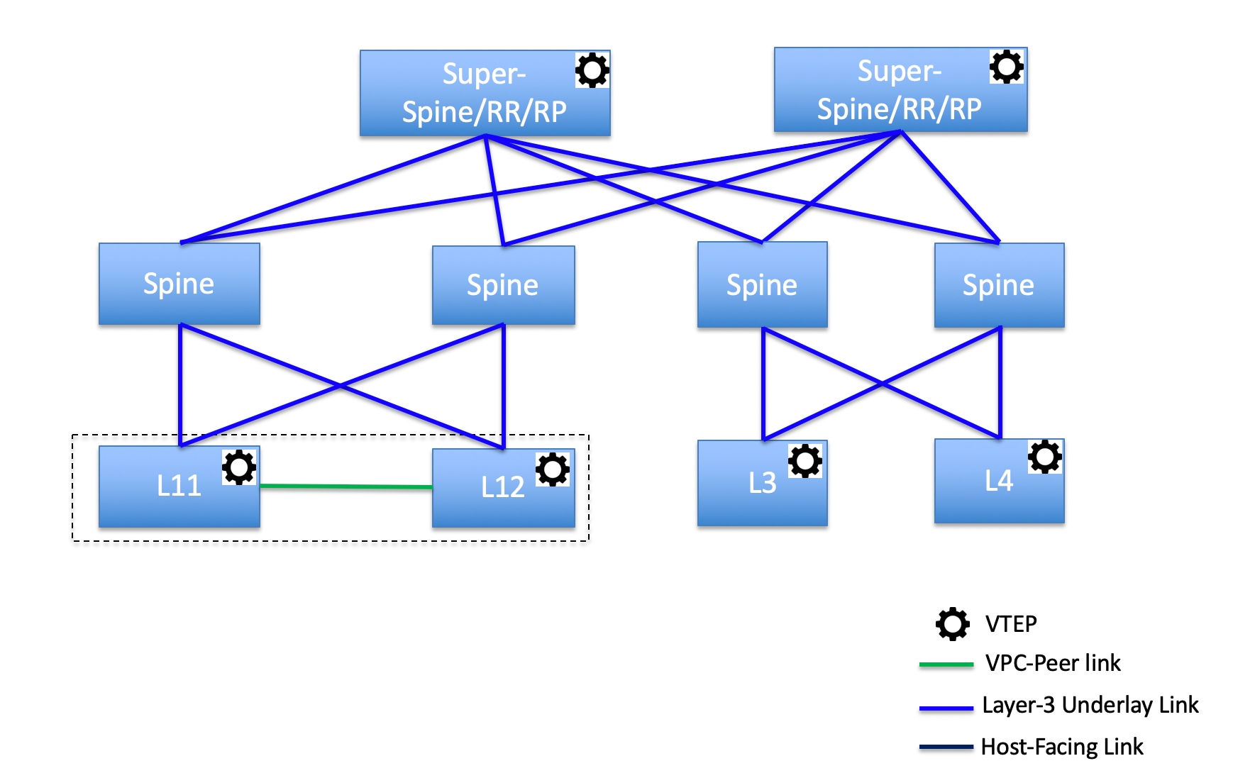
In this topology, leaf switches are connected to spines, and spines are connected to super spine switches that can be super spines, border super spines, and border gateway super spines.
Topology 2: Super spine switches connected to a border
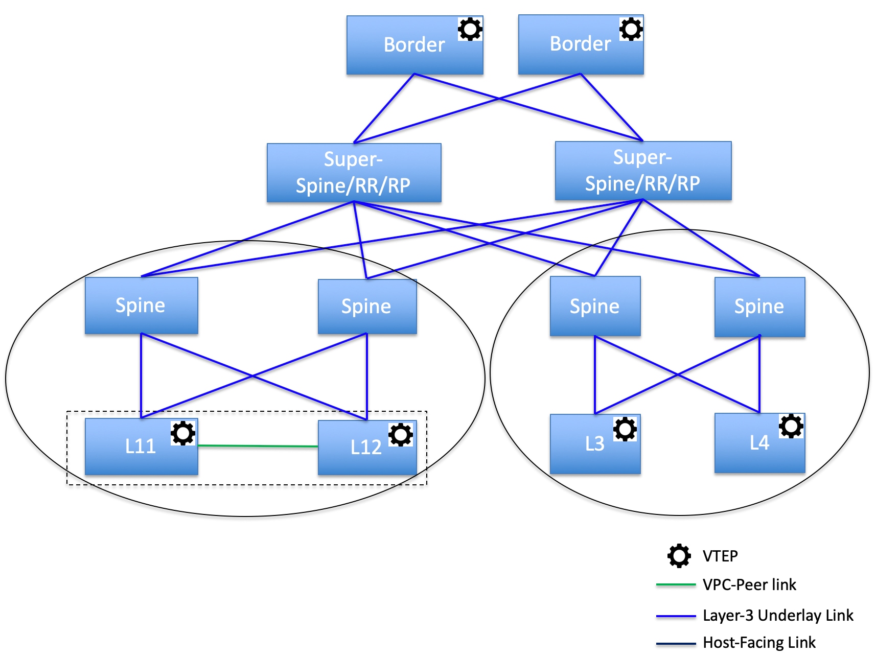
In this topology, there are four leaf switches connecting to the spine switches, which are connected to two super spine switches. These super spine switches are connected to the border or border gateway leaf switches.
Create a vPC setup
You can create a vPC setup for a pair of switches in the External and Inter-Fabric Connectivity fabric. Ensure that the switches are of the same role and connected to each other.
-
Right-click one of the two designated vPC switches and choose vPC Pairing.
The Select vPC peer dialog box comes up. It contains a list of potential peer switches. Ensure that the Recommended column for the vPC peer switch is updated as true.
Alternatively, you can also navigate to the Tabular view from the Actions pane. Choose a switch in the Switches tab and click vPC Pairing to create, edit, or unpair a vPC pair. However, you can use this option only when you choose a Cisco Nexus switch.
-
Click the radio button next to the vPC peer switch and choose vpc_pair from the vPC Pair Template drop-down list. Only templates with the VPC_PAIR template sub type are listed here.
The vPC Domain and vPC Peerlink tabs appear. Update the required fields in the tabs to create the vPC setup. The description for each field is displayed at the extreme right.
Field Description vPC Domain tab
Enter the vPC domain details.
vPC+
If the switch is part of a FabricPath vPC + setup, enable this check box and enter the FabricPath switch ID field.
Configure VTEPs
Check this check box to enter the source loopback IP addresses for the two vPC peer VTEPs and the loopback interface secondary IP address for NVE configuration.
NVE interface
Enter the NVE interface. vPC pairing configures only the source loopback interface. Use the freeform interface manager for additional configuration.
NVE loopback configuration
Enter the IP address with the mask. vPC pairing only configures the primary and secondary IP address for a loopback interface. Use the freeform interface manager for additional configuration.
vPC Peerlink tab
Enter the vPC peer-link details.
Switch Port Mode
Choose trunk or access or fabricpath.
-
If you choose trunk, then the corresponding fields (Trunk Allowed VLANs and Native VLAN) are enabled. If you choose access, then the Access VLAN field is enabled. If you choose fabricpath, then the trunk and access port-related fields are disabled.
-
Click Save.
The vPC setup is created.
Updating vPC setup details
-
Right-click a vPC switch and choose vPC Pairing.
The vPC peer dialog box comes up.
-
Update the field(s) as needed.
When you update a field, the Unpair icon changes to Save.
-
Click Save to complete the update.
After creating a vPC pair, you can view vPC details on the vPC Overview page.
Undeploy a vPC setup
-
Right-click a vPC switch and choose vPC Pairing.
The vPC peer page comes up.
-
Click Unpair at the bottom right part of the page.
The vPC pair is deleted and the fabric topology page appears.
-
Click Deploy Config.
-
(Optional) Click the value under the Recalculate Config column.
View the pending configuration in the Config Preview dialog box. The following configuration details are deleted on the switch when you unpair: vPC feature, vPC domain, vPC peerlink, vPC peerlink member ports, loopback secondary IPs, and host vPCs. However, the host vPCs and port channels are not removed. Delete these port channels from the Interfaces window if required.
Resync the fabric if it is out of sync.
When you unpair, only PTIs are deleted for following features, but the configuration is not cleared on the switch during Deploy Config: NVE configuration, LACP feature, fabricpath feature, nv overlay feature, loopback primary ID. In case of host vPCs, port channels and their member ports are not cleared. You can delete these port channels from the Interfaces page if required. You can continue using these features on the switch even after unpairing.
If you are migrating from fabricpath to VXLAN, you need to clear the configuration on the device before deploying the VXLAN configuration.
Perform actions on switches
Change Mode
To change a mode for the switch, perform the following steps:
-
Navigate to Manage > Fabrics.
-
Click on a VXLAN EVPN fabric.
The Fabric Overview page appears.
-
Click the Inventory > Switches tab.
-
Click the check box for the switch you want to change modes for.
-
Choose Actions > Maintenance > Change Mode.
The Change Mode dialog box appears.
-
Click Maintenance from the drop-down list to change to maintenance mode or click Normal to change to normal mode.
-
Click Deploy Now to change the switch mode now or click Deploy later to change the switch mode later.
Waiting for a switch to change modes
There are multiple ways to change modes for a switch.
-
Enable the Wait for switch mode change to maintenance on deploy option from the Fabric Overview > Switches page or from the Actions drop-down list on the Manage > Inventory > Switches page.
-
Alternatively, you can click the View in topology option on the Fabric Overview page to access a switch on the Topology page.
-
You can then right-click on the switch from the Topology page and click Maintenance > Change Mode to access the Change Mode dialog box.
To enable waiting for a switch to change modes, perform these steps:
-
Navigate to Manage > Fabrics.
-
Click on a Data Center VXLAN EVPN fabric.
The Fabric Overview page appears.
-
Click the Inventory > Switches tab.
-
Click the check box for the switch you want to change modes for.
-
Click Actions > Maintenance > Change Mode.
The Change Mode dialog box appears.
-
Click Maintenance from the drop-down list to change to maintenance mode or click Normal to change to normal mode.
-
Click the Wait for switch mode change to maintenance on deploy check box.
-
Click the Deploy Now button to change the switch mode.
Because you enabled the Wait for switch mode change to maintenance on deploy check box, the Deploy later option is grayed out. Nexus Dashboard retains the last action of the user for this check box.
It may take two to three minutes for the change-mode process to complete.
Limitations of waiting for a switch to change modes
-
Support is provided for Cisco NX-OS devices only.
-
Support is not provided for Catalyst or Catalyst 9K switches. If you try to change the mode of a non-Cisco NX-OS device, you receive an error message.
-
You cannot change the mode of a switch using change control.
Provision RMA
To change mode for the switch, perform these steps:
-
Click the check box for the required switch.
-
Click Actions > Maintenance > Provision RMA.
The Provision RMA - switch_name page appears.
-
Enter the admin password in the Admin password field in the Switch Credentials area of the page.
The Provision RMA page shows the replacement device 5-10 minutes after it is powered on.
-
Choose one of the discovery options, Admin user and supplied password or Specicy a new user.
-
If you choose Specify a new user, you will see Local and Credential Store tabs.
-
If you haven’t configured credential store, in the Local tab, enter the Username, Password, and Authentication/Privacy details of the switch.
-
If you have configured credential store, in the Credential Store tab, enter the credential store key and authentication/privacy key.
You will see the Credential Store tab only if you configured system certificate and mapped to CyberArk feature. For more information on CA certificates and credential store, see Managing Certificates in your Nexus Dashboard and Configuring Users and Security.
-
Change serial number
You can change the serial number of switches. While pre-provisioning devices, you can provide dummy values for the serial number of the switch. After you configure the network successfully, you can change the serial number with the appropriate serial number of the switch.
Before changing the serial number of the switches, on the main page, click Actions > Recalculate and deploy to save the latest data for the switch.
The change of serial number is supported only for Nexus 9000 series switches. After you change a serial number with the actual serial number, we recommend to re-POAP the device during the power-on bootstrap. For more information, see Add switches using the bootstrap mechanism.
Copy run start
To copy the existing switch configuration to start the configuration, perform these steps:
-
Click the check box for the required switch.
-
Click Actions > Maintenance > Copy Run Start.
The Copy Running Config to Startup Config page appears.
The Progress column shows the process in progress and the Status Description column shows the deployment status.
A confirmation dialog box appears.
-
Click OK.
The status description column displays Deployment completed and the progress column displays in green.
-
Click Close to close this page.
Reload
-
To reload the required switch, click Actions > Maintenance > Reload.
A confirmation dialog box appears.
-
Click Confirm.
Restore switch
You can restore a Cisco Nexus switch in external fabrics and LAN classic fabrics from Nexus Dashboard. The information you restore at the switch level is extracted from the fabric-level backups. The switch level restore doesn’t restore fabric-level intents and other configurations applied using the fabric settings. Only switch-level intents are restored. Therefore, after you restore a switch, it might go out-of-sync because the fabric-level intents aren’t restored. Perform a fabric-level restore to restore the intents as well. You can restore only one switch at a time. You can’t restore a switch if the fabric where it’s discovered is part of an MSD fabric.
-
Click Actions > Maintenance > Restore Switch.
The Restore Switch page appears and you are in the Select a Backup tab.
The Select a Backup tab displays the fabric backup details. It includes the following information:
Field
Description
Backup Date
Specifies the backup date and time.
Backup Version
Specifies the name of the backup.
Backup Tag
Specifies the version number of the switch.
Nexus Dashboard Version
Specifies the Nexus Dashboard version details.
Backup Type
Specifies the type of backup, either manual or automatic.
You can choose the automatic, manual, or golden backup. These backups are color-coded. Automatic backups are indicated in blue color.
Manual backups are indicated in midnight blue color. Golden backups are indicated in orange color. The automatic backups have only the versions in their names. Whereas the manual backups have tag names, which you gave when you initiated a manual backup, along with the version in the backup name. Hover over a backup to see the name.
You can now mark the backups that you don’t want to delete even after you reach the archiving limit. These backups are the golden backups. You can’t delete golden backups of fabrics. However, Nexus Dashboard archives only up to 10 golden backups.
-
Click the radio button for the required backup to mark it as golden.
-
Click Actions > Mark as golden.
A confirmation dialog box appears.
-
Click Confirm.
-
Click the radio button for backup to delete from the golden backup.
-
Click Actions > Remove as golden.
A confirmation dialog box appears.
-
Click Confirm.
Most of this information is at the fabric level, and may or may not directly impact the proceedings of the switch-level restore.
-
Click Next to move to the Restore Preview step.
You can view information about the switch name, switch serial, IP address, status, restore supported, delta configuration, and the VRF details.
-
(Optional) Click Get Config to preview the device configuration details.
The Config Preview dialog appears, which has the following three tabs.
Field
Description
Backup Config
This tab displays the backup configuration for the selected device.
Current Config
This tab displays the current running configuration of the selected device.
Side-by-side Comparison
This tab displays the current running configuration on the switch, and the backup configuration, which is the expected configuration.
-
Click Restore Intent to proceed to the Restore Status step in restoring.
The restore status and description appears for the switch.
-
Click Finish after the restore process is complete.
-
You can’t go back to the previous step because the fabric configuration changes.
-
If the restore fails, the switch rolls back to the previous configuration.
Show commands
You can execute show commands on switches and download the output. For more information, see Execute show commands on switches.
Exec commands
The commands available in the EXEC mode include the show commands that display the device status and configuration information, the clear commands, and other commands that perform actions that you do not save in the device configuration.
The following procedure shows how to run EXEC commands in Nexus Dashboard:
-
Choose Actions > Maintenance > Exec Commands.
The Switch show commands page appears.
-
From the Template drop-down list, click exec_freeform or exec_elam_capture.
There is a known issue where the system might choose the exec_elam_capture template by default, which is the incorrect default option. Before entering the command in the next step, manually change the default option to exec_freeform, if necessary.
-
Enter the commands in the Freeform CLI for exec_freeform and the required IP addresses.
-
Click Deploy to run the EXEC commands.
-
On the CLI Execution Status page, you can check the status of the deployment.
-
Click Detailed Status under the Command column to view the details.
-
On the Command Execution Details page, click the information under the the CLI Response column to view the output or the response.
Delete switches
You can delete one or more existing switches.
-
Click Actions > Delete Switch(es).
A confirmation dialog box appears.
-
Click Confirm.
Execute show commands on switches
Nexus Dashboard allows you to execute show commands on multiple switches. You can collect the output from the CLI commands in a zip file for each switch.
Follow these steps to execute show commands on switches.
-
On the Nexus Dashboard UI, choose Manage > Inventory > Switches.
-
Choose the switches on which you want to execute the show commands.
You must choose more than one switch to run the set of CLI commands simultaneously.
-
From the Actions drop-down list, choose Maintenance > Show Commands.
The Execute Switch CLI page appears with Configure and Execute sections.
-
In the Configure section, click View Switches to view the names of the switches for which you want to execute the show commands.
-
In the Session Timeout area, enter a value for the session timeout limit. The session timeout value range is 2 to 10 minutes. The default timeout value is 5 minutes.
-
Choose one of these options to provide the CLI commands you want to execute on the switches.
-
Enter the CLI commands (one command per line) you want to execute on the switches in the CLI Commands text box, or
-
Click on the Read Commands File button to upload a .txt file with a list of CLI commands.
You can execute a maximum of 10 commands at a time.
-
-
Click Execute.
When command execution is complete on all switches, the Execute CLI Output dialog box appears with the command output.
For example, the following Execute CLI Output displays the show version command output for the switches.
Execute CLI Output ============= Execute CLI command status digest ============= 192.0.2.0:JPG2401008M success 192.0.2.1:JPG234600G9 success ========== End of Execute CLI command status digest ========= ************* 192.0.2.0:JPG2401008M ************* show version Cisco Nexus Operating System (NX-OS) Software TAC support: http://www.cisco.com/tac Documents: http://www.cisco.com/en/US/products/ps9372/tsd_products_support_series_home.html Copyright (c) 2002-2022, Cisco Systems, Inc. All rights reserved. The copyrights to certain works contained herein are owned by other third parties and are used and distributed under license. Some parts of this software are covered under the GNU Public License. A copy of the license is available at http://www.gnu.org/licenses/gpl.html. Software BIOS: version 1.04.0 loader: version N/A kickstart: version 9.3(2) system: version 9.3(2) BIOS compile time: 03/04/2022 kickstart image file is: bootflash:///m9148-s6ek9-kickstart-mz.9.3.2.bin kickstart compile time: 10/31/2022 12:00:00 [12/13/2022 09:17:38] system image file is: bootflash:///m9148-s6ek9-mz.9.3.2.bin system compile time: 10/31/2022 12:00:00 [12/13/2022 10:34:04] Hardware cisco MDS 9148T 48X32G FC (1 RU) Chassis ("4/8/16/32 Gbps FC/Sup-4") Intel(R) Xeon(R) CPU D-1530 @ 2.40GHz with 5751760 kB of memory. Processor Board ID JAE23520JMB Device name: DCNM-9148T-91 bootflash: 3735552 kB Kernel uptime is 667 day(s), 20 hour(s), 13 minute(s), 28 second(s) Last reset Reason: Unknown System version: 9.3(2) Service: plugin Core Plugin ****** END OF 192.0.2.0:JPG2401008M OUTPUT ****** ************* 192.0.2.1:JPG234600G9 ************* show version Cisco Nexus Operating System (NX-OS) Software TAC support: http://www.cisco.com/tac Documents: http://www.cisco.com/en/US/products/ps9372/tsd_products_support_series_home.html Copyright (c) 2002-2022, Cisco Systems, Inc. All rights reserved. The copyrights to certain works contained herein are owned by other third parties and are used and distributed under license. Some parts of this software are covered under the GNU Public License. A copy of the license is available at http://www.gnu.org/licenses/gpl.html. Software BIOS: version 1.04.0 loader: version N/A kickstart: version 9.3(2) system: version 9.3(2) BIOS compile time: 03/04/2022 kickstart image file is: bootflash:///m9148-s6ek9-kickstart-mz.9.3.2.bin kickstart compile time: 10/31/2022 12:00:00 [12/13/2022 09:17:38] system image file is: bootflash:///m9148-s6ek9-mz.9.3.2.bin system compile time: 10/31/2022 12:00:00 [12/13/2022 10:34:04] Hardware cisco MDS 9148T 48X32G FC (1 RU) Chassis ("4/8/16/32 Gbps FC/Sup-4") Intel(R) Xeon(R) CPU D-1530 @ 2.40GHz with 5751756 kB of memory. Processor Board ID JAE23520JK0 Device name: DCNM-C9132T-93 bootflash: 3735552 kB Kernel uptime is 323 day(s), 1 hour(s), 50 minute(s), 16 second(s) Last reset at 595234 usecs after Wed Jul 10 09:50:45 2024 Reason: Reset Requested by CLI command reload System version: 9.3(2) Service: plugin Core Plugin ****** END OF 192.0.2.1:JPG234600G9 OUTPUT ****** -
Click Close to close the output dialog box.
You are returned to the Execute Switch CLI page, where the table displays the switch, the associated fabric, and the CLI execution status.
-
Click on one of these options.
-
Show Output — to display the Execute CLI Output again.
When the output is larger than a few MBs, you can scroll down to view the complete output in the Execute CLI output dialog box.
-
Download Output — to download the command output as a zip file.
-
Done — to return to the Inventory page.
-
If the switch is not reachable via CLI, then Nexus Dashboard will display an error message.
View information on a single switch
You can view information for a switch after it has been added to your fabric.
-
Navigate to the main Inventory page.
For more information, see Navigate to the Inventory page.
-
If you navigated to the Inventory page from the fabric, click the Inventory > Switches tab, or click the switch from the Inventory area of the Manage > Fabric > Overview page.
The Inventory > Switches page shows information on already-configured switches.
-
Click on a switch from the list of already-configured switches.
The Switch Overview page for that switch appears.
Field Description Switch Info
Specifies the switch information such as switch name, IP address, switch model and other details.
Alarms
Specifies the alarms configured on the selected switch.
Performance
Specifies the CPU utilization and memory utilization for the switch.
Interfaces
Specifies the interface details.
Modules/FEX
Specifies the modules and FEX information.
Reports
Specifies the reports.
Hardware
This tab contains these sub tabs:
Modules
To view the inventory information for modules from Nexus Dashboard, perform these steps:
-
Choose Manage > Inventory.
-
Click a switch to open the Switch Overview page.
-
Click Hardware > Modules.
The Modules tab displays with a list of all of your switches.
You can view the required information in table format.
-
Enter filter criteria in Filter by Attributes.
You can view the following information.
Column
Description
Name
Displays the module name.
Model Name
Displays the model name.
Serial Number
Displays the serial number.
Type
Displays the type of the module.
Oper Status
Displays the operational status of the module.
Slot
Displays the slot number.
Module Type
Displays the module type.
Module Version
Displays the module version.
Hardware Revision
Displays the hardware version of the module.
Software Revision
Displays the software version of the module.
Asset ID
Displays the asset id of the module.
Bootflash
-
You can view the following information on the Bootflash tab.
Card
Description
Total Space
Displays the total space on the switch bootflash.
Used Space
Displays the used space on the switch bootflash.
Available Space
Displays the available space on the switch bootflash.
-
You can filter by these attributes.
Field
Description
File Name
Displays the file name on the switch bootflash.
Date
Displays the last modified date for all the files and directories on the switch bootflash.
Size (Bytes)
Displays the size in bytes of all the files and directories on the switch bootflash.
-
Choose Actions > Delete to delete files to increase the available space on the switch.
When you delete files, the file details in this page are updated every 24 hours or when you perform an upload or recalculate compliance operations in Fabric Software. For more information, see Managing Your Fabric Software.
FEX
Fabric Extender (FEX) allows you to manage a Cisco Nexus 2000 series FEX and its association with the Cisco NX-OS switch attached to it. An FEX is connected to the switch through physical Ethernet interfaces or a port channel. By default, the switch does not allow the attached FEX to connect until it has been assigned a chassis ID and is associated with the connected interface. You can configure an FEX host interface port as a routed or Layer 3 port. However, you cannot tie routing protocols to this routed interface.
-
You can view the following information on the FEX tab.
-
You can filter by these attributes.
Field
Description
Fex Id
Uniquely identifies an FEX that is connected to a Cisco NX-OS device.
Fex Desc
Displays the description configured for the FEX.
Fex Version
Specifies the version of the FEX that is associated with the switch.
Fex Pin
Displays the integer value that denotes the maximum pinning uplinks of the FEX that is active at the time.
State
Specifies the status of the FEX as associated with the Cisco Nexus switch.
Model
Displays the model of the FEX.
Serial No
Displays the serial number of the FEX.
If this configured serial number and the serial number of the FEX are not the same, the FEX is not active.
Port Channel
Specifies the port channel number to which the FEX is physically connected to the switch.
Ethernet
Specifies the physical interfaces to which the FEX is connected.
vPC ID
Specifies the vPC ID configured for the FEX.
-
Choose Actions > Show Command to
Connectivity
For more information on Connectivity, see Working with Connectivity in Your Nexus Dashboard LAN Fabrics.
Configuration policies
For information about configuration policies and details about how to add policies, see the "Configuration policies" section in Working with Configuration Policies for Your Nexus Dashboard LAN or IPFM Fabrics.
Anomalies
For more information about Anomalies, see Detecting Anomalies and Identifying Advisories in Your Nexus Dashboard.
Advisories
Fore more information about Advisories, see Detecting Anomalies and Identifying Advisories in Your Nexus Dashboard.
History
The History tab displays information about audit logs, the deployment, and policy change history.
-
Choose Manage > Fabrics.
-
Click a fabric name to open the Fabric Overview page and then click the History tab.
For more information, see Viewing History in Your Nexus Dashboard Fabrics.
View switch port status information for IPFM fabrics
You can view port status information similar to what you would see on the front panel of a switch. You can toggle between the different Switch view tabs to view both port status and port anomaly information, port status information only, or port anomaly information only. Nexus Dashboard displays the Port Status Only tab by default.
This feature is supported for these fabric types.
-
IPFM
-
Enhanced Classic LAN
Guidelines and limitations for viewing switch port status information
-
No support for real-time updates for viewing port status information.
-
Click Refresh to obtain real-time status updates.
-
Limited attributes are available.
How to view switch port status information
Follow these steps for viewing switch port status information for IPFM fabrics.
-
Navigate to the main Inventory page.
For more information, see Navigate to the Inventory page.
-
If you navigated to the Inventory page from the fabric, click the Inventory > Switches tab, or click the switch from the Inventory area of the Manage > Fabric > Overview page.
The Inventory > Switches page shows information on already-configured switches.
-
Click on a switch from the list of already-configured switches.
The Switch Overview page for that switch appears.
-
Navigate to the Switch view area of the Switch Overview page.
Nexus Dashboard displays a color-coded visualization of the switch ports.
Red indicates a down operational status, while green indicates an up operational status.
-
View the port diagram key for the detailed legend.
-
You can hover over a switch port to view the operational status, anomaly level, Layer 3 neighbors connected to the interface (if any), and the name of the interface.
You can also view the LLDP or CDP neighbors in the switch port view.
-
When you click on a port within the Switch view, you can navigate directly to the Switch Overview > Connectivity > Interfaces tab for performing any action listed under the Actions drop-down list. For more information on interfaces, see the "Interfaces" section of Working with Connectivity in Your Nexus Dashboard LAN Fabrics.
View hardware resources
Follow these steps for viewing hardware resources for a switch.
-
Navigate to the Switch view area of the Switch Overview page.
-
Click View hardware resources to view a slide-in that appears with information on the hardware resources for a specific switch in real time.
Real-time visualization helps you view up-to-date information about your hardware resources. Hardware Resources shows the variations in the hardware resources over the chosen time range. These are displayed with the percentage utilized per component.
-
CPU
-
Memory
-
Power Supply
-
-
Ensure that you enable performance monitoring for your IPFM fabrics.
-
Click the Details link under Power supply to see it’s details. The Details link for Memory and CPU are not supported in this release.
View capacity
Follow these steps for viewing capacity for a switch.
-
Navigate to the Switch view area of the Switch Overview page.
-
Click View capacity to view a slide-in that appears with capacity information for the switch.
Nexus Dashboard grays out the View capacity link for IPFM fabrics.
Additional settings
The following sections provide information for additional settings that might be necessary when configuring switches for LAN or IPFM fabrics.
Enable freeform configurations on fabric switches
In Nexus Dashboard, you can add custom configurations through freeform policies in the following ways:
-
Fabric-wide:
-
On all leaf, border leaf, and border gateway leaf switches in the fabric, at once.
-
On all spine, super spine, border spine, border super spine, border gateway spine and border switches, at once.
-
-
On a specific switch at the global level.
-
On a specific switch on a per network or a per VRF level.
-
On a specific interface on a switch.
Leaf switches are identified by the roles Leaf, Border, and Border Gateway. The spine switches are identified by the roles Spine, Border Spine, Border Gateway Spine, Super Spine, Border Super Spine, and Border Gateway Super Spine.
You can deploy freeform CLIs when you create a fabric or when a fabric is already created. The following examples are for an existing fabric. However, you can use this as a reference for a new fabric.
Deploy fabric-wide freeform CLIs on leaf and spine switches
-
Choose Manage > Fabrics.
-
Choose the fabric, and select Edit Fabric Settings from the Actions drop-down list.
(If you are creating a fabric for the first time, click Create Fabric).
-
Click Fabric Management.
-
Click Advanced and update the following fields:
-
Leaf Freeform Config - In this field, add configurations for all leaf, border leaf, and border gateway leaf switches in the fabric.
-
Spine Freeform Config - In this field, add configurations for all Spine, Border Spine, Border Gateway Spine, Super Spine, Border Super Spine, and Border Gateway Super Spine switches in the fabric.
Copy-paste the intended configuration with the correct indentation, as seen in the running configuration on the Nexus switches. For more information, see Resolve freeform config errors in switches.
-
-
Click Save. The fabric topology screen comes up.
-
Click Recalculate and deploy from the Actions drop-down list to save and deploy the configurations.
Configuration Compliance functionality ensures that the intended configuration as expressed by those CLIs are present on the switches and if they are removed or there is a mismatch, then Nexus Dashboard flags it as a mismatch and indicates that the device is out-of-sync.
Incomplete Configuration Compliance - On some Cisco Nexus 9000 Series switches, in spite of configuring pending switch configurations using the Recalculate and deploy option, there could be a mismatch between the intended and switch configuration. To resolve the issue, add a switch_freeform policy to the affected switch (as explained in the Deploy freeform CLIs on a specific switch on a per VRF/network basis). For example, consider the following persistent pending configurations:
line vty
logout-warning 0
After adding the above configurations in a policy and saving the updates, click Recalculate and deploy to complete the deployment process.
To bring back the switch in-sync, you can add the above configuration in a switch_freeform policy saved and deployed onto the switch.
Deploy freeform CLIs on a specific switch
-
Choose Manage > Fabrics.
-
Click the necessary fabric in the Name column.
The Overview page for that fabric appears.
-
Choose Configuration Policies > Policies.
-
Click Actions > Add policy.
The Create Policy screen comes up.
To provision freeform CLIs on a new fabric, you have to create a fabric, import switches into it, and then deploy freeform CLIs.
-
Choose the switch where you want to deploy the freeform CLIs, then click Next.
-
In the Priority field, the priority is set to 500 by default. You can choose a higher priority (by specifying a lower number) for CLIs that need to appear higher up during deployment. For example, a command to enable a feature should appear earlier in the list of commands.
-
In the Description field, provide a description for the policy.
-
From the Template Name field, choose freeform_policy.
-
Add or update the CLIs in the Switch Freeform Config box.
Copy-paste the intended configuration with the correct indentation, as seen in the running configuration on the Nexus switches. For more information, see Resolve freeform config errors in switches.
-
Click Save.
After the policy is saved, it gets added to the intended configurations for that switch.
-
From the fabric Overview page, click Inventory > Switches and choose the required switches.
-
On the Switches tab, click Actions > Deploy.
Pointers for freeform_policy policy configuration:
-
You can create multiple instances of the policy.
-
For a vPC switch pair, create consistent freeform_policy policies on both the vPC switches.
-
When you edit a freeform_policy policy and deploy it onto the switch, you can see the changes being made (in the Side-by-side tab of the Preview option).
Freeform CLI configuration examples
Console line configurations
This example involves deploying some fabric-wide freeform configurations (for all leaf, and spine switches), and individual switch configurations.
Fabric-wide session timeout configuration:
line console
  exec-timeout 1
Console speed configuration on a specific switch:
line console
  speed 115200
For Cisco Nexus 9804 and Cisco Nexus 9808 switches, you need to create a switch_freeform policy for the non-default console speed, as these switches only support a speed of 115200.
IP frefix list/route-map configurations
IP prefix list and route-map configurations are typically configured on border devices. These configurations are global because they can be defined once on a switch and then applied to multiple VRFs as needed. The intent for this configuration can be captured and saved in a switch_freeform policy. As mentioned earlier, note that the configuration saved in the policy should match the show run output. This is especially relevant for prefix lists where the NX-OS switch may generate sequence numbers automatically when configured on the CLI. An example snippet is shown below:
ip prefix-list prefix-list-name1 seq 5 permit 20.2.0.1/32
ip prefix-list prefix-list-name1 seq 6 permit 20.2.0.2/32
ip prefix-list prefix-list-name2 seq 5 permit 192.168.100.0/24
ACL configurations
Access control list (ACL) configurations are typically configured on specific switches and are not fabric-wide configurations. When you configure ACLs as freeform CLIs on a switch, you should include sequence numbers. Otherwise, there will be a mismatch between the intended and the running configurations.
Following is a configuration example with sequence numbers:
ip access-list ACL_VTY
  10 deny tcp 172.29.171.67/32 172.29.171.36/32
  20 permit ip any any
ip access-list vlan65-acl
  10 permit ip 69.1.1.201/32 65.1.1.11/32
  20 deny ip any any

interface Vlan65
  ip access-group vlan65-acl in
line vty
  access-class ACL_VTY in
If you have configured ACLs without sequence numbers in a freeform_policy policy, update the policy with the sequence numbers as shown in the running configuration of the switch.
After the policy is updated and saved, right-click the device and select the per switch Deploy Config option to deploy the configuration.
In previous releases, when you perform a Recalculate & Deploy on a fabric where switches are imported with the Preserve Config option enabled (a Brownfield deployment), the IP ACL configuration for a VXLAN fabric is captured in the switch_freeform policy, along with the non-matched switch configuration. For the same situation in an Enhanced Classic LAN fabric, where you have a Brownfield import with the Preserve Config option enabled, the same configuration information is captured into a smaller subset of individual ACL freeforms.
Now, for both VXLAN and Enhanced Classic LAN fabrics:
-
If the ACL configurations match with the ip_acl and ipv6_acl nvPairs, then those configurations will be captured in the ip_acl and ipv6_acl policies.
-
If the ACL configurations do not match with the ip_acl and ipv6_acl nvPairs, then those configurations will be captured in a smaller subset of per ACL freeforms, which means that MAC-based ACLs would continue to be captured into their individual switch freeforms.
Resolve freeform config errors in switches
Copy and paste the running-config to the freeform config with correct indentation, as seen in the running configuration on the NX-OS switches. The freeform config must match the running config. Otherwise, configuration compliance in Nexus Dashboard marks the switches as out-of-sync.
Following is an example of the freeform config of a switch.
feature bash-shell
feature telemetry

clock timezone CET 1 0
# Daylight saving time is observed in
Metropolitan France from the last Sunday in March (02:00 CET) to the last Sunday in October (03:00 CEST) clock summer-time CEST 5 Sunday March 02:00 5 Sunday October 03:00 60
clock protocol ntp

telemetry
  destination-profile
    use-vrf management
The highlighted line about the daylight saving time is a comment that is not displayed in the show running config command output. Therefore, configuration compliance marks the switch as out-of-sync because the intent does not match the running configuration.
Next, check the running config in the switch for the clock protocol.
spine1# show run all | grep "clock protocol"
clock protocol ntp vdc 1
You can see that vdc 1 is missing from the freeform config.
In this example, let us copy-paste the running config to the freeform config.
Following is the updated freeform config:
feature bash-shell
feature telemetry

clock timezone CET 1 0
clock summer-time CEST 5 Sunday March 02:00 5 Sunday October 03:00 60 clock protocol ntp vdc 1

telemetry
  destination-profile
    use-vrf management
After you copy-paste the running config and deploy, the switch will be in-sync. When you click Recalculate Config, click the Pending Config column. You can view the Side-by-Side Comparison for information about the difference between the defined intent and the running config.
Deploy freeform CLIs on a specific switch on a per VRF/network basis
-
Choose Manage > Fabrics.
-
Click the necessary fabric in the Name column.
The Overview page for that fabric appears.
-
Choose Segmentation and security > VRFs.
-
Click Actions > Create.
The Create VRF page appears.
-
Select an individual switch.
The VRF attachment form is displayed, listing the switch that is selected. In the case of a vPC pair, both switches belonging to the pair are displayed.
-
Under the CLI Freeform column, select the button labeled Freeform config. This option allows a user to specify additional configurations that should be deployed to the switch along with the VRF profile configuration.
-
Add or update the CLIs in the Free Form Config CLI box. Copy-paste the intended configuration with the correct indentation, as seen in the running configuration on the Nexus switches. For more information, see Resolve freeform config errors in switches.
-
Click Deploy Config.
The Freeform config button will be gray when there is no per VRF per switch config specified. The button will be blue when some config has been saved by the user.
After the policy is saved, click Save on the VRF Attachment pop-up to save the intent to deploy the VRF to that switch. Ensure that the checkbox on the left next to the switch is checked.
-
(Optional) Click Preview to look at the configuration that will be pushed to the switch.
-
Click Deploy Config to push the configuration to the switch.
The same procedure can be used to define a per network per switch configuration.
Add proper indentation for interface free-form configurations
Ensure to use correct indentation and include two or more leading spaces in interface free-form configurations. When incorrect indentation is used, NDFC may remove leading spaces and configuration is not applied.
For example, to configure vPC ESI for an active-active firewall setup, the following configuration is required on the vPC port-channel interface:
interface port-channel 1
  vpc 1
  ethernet-segment vpc
    esi 0012.0000.0000.1200.0102 tag 1012
When configuring this using interface free-form configuration in NDFC, ensure that the esi command is nested under the ethernet-segment vpc stanza with proper indentation.
For example:
interface port-channel 1
  ethernet-segment vpc
    esi 0012.0000.0000.1200.0102 tag 1012
If the indentation is incorrect, NDFC may remove leading spaces and deploy the configuration as:
interface port-channel 1
  ethernet-segment vpc
  esi 0012.0000.0000.1200.0102 tag 1012
In this case, the esi 0012.0000.0000.1200.0102 tag 1012 command is treated as a top-level interface command, which is not supported on N9K-FX, FX2, GX, and FX3 platforms, and therefore the configuration will not be applied.
Configuring ToR switches and deploying networks
These sections provide information and procedures on configuring ToR switches and deploying networks:
Configuring ToR switches and deploying networks in Data Center VXLAN EVPN fabrics
Overview
Layer 2 Top-of-Rack (ToRs) are considered as replacements for FEXs. In earlier releases, you can add the Layer 2 ToR switches in an external fabric, and connect them to the leaf switches in a Data Center VXLAN EVPN fabric. The network overlay attachments were managed from the VXLAN EVPN Multi-Site domain as both Data Center VXLAN EVPN fabrics with spine/leaf and external fabrics with ToRs were added to a VXLAN EVPN Multi-Site domain. Now, you can add Layer 2 ToR devices in the same fabric as in a spine/leaf Data Center VXLAN EVPN fabric. This allows a single configuration point for deploying and extending networks for a VXLAN fabric topology with Layer 2 ToRs.
It is not recommended to have a combination of FEX and ToRs in leaf switches due to a scale limitation.
You can physically connect a Layer 2 ToR in one of the following ways:
-
Connected to a leaf through a port-channel
-
Connected to a vPC pair of leafs through a vPC
-
Connected to one of the leafs in a vPC pair through a port-channel
You can configure a pair of Layer 2 ToRs in a vPC. A ToR vPC pair can only be connected to a leaf vPC pair through back-to-back vPC (also known as a double-sided vPC).
Guidelines for configuring ToR switches in Data Center VXLAN EVPN fabrics
You add ToR devices to a Data Center VXLAN EVPN fabric in the same way as all other devices.
-
ToR role must be set on ToR devices before you perform a Recalculate and deploy operation.
-
Perform a Recalculate and deploy after any change of ToR pairings/unpairings.
-
ToRs must be physically connected to the intended parent leaf switches.
-
vPC pairing should be done before a leaf-ToR pairing/unpairing.
-
ToR pairing/unpairing can be done on an individual leaf, or a leaf vPC pair.
-
Network-overlay association for ToR switches are managed from their parent leaf(s).
-
ToR ports are shown as additional ports under a leaf.
-
Nexus Dashboard handles all intermediate configurations transparently.
-
Deletion of a leaf will also delete all associated child ToR devices.
-
A leaf can be connected to many ToRs, but a ToR can be connected to only one leaf or leaf-vPC pair.
Limitations for configuring ToR switches in Data Center VXLAN EVPN fabrics
-
Interface groups on Layer 2 ToRs are not supported.
-
Brownfield import on Layer 2 ToRs is not supported.
Configure ToR switches in Data Center VXLAN EVPN fabrics
On the Edit Fabric page, click the Advanced tab and specify the applicable fabric settings.
| Field | Description |
|---|---|
|
Spanning Tree Root Bridge Protocol |
Choose the protocol from the drop-down list for configuring a root bridge. The available protocols are:
We recommend that you use the mst protocol for a Layer 2 ToR. |
|
Spanning Tree VLAN Range |
Specify the VLAN range. The default value is 1 - 3967. |
|
MST Instance Range |
Specify the MST instance range. The default value is 0. |
|
Spanning Tree Bridge Priority |
Specify the bridge priority for the spanning tree in increments of 4096. |
Supported topologies for ToR switches
The following topologies with ToR switches are supported:
Only Cisco Nexus 9000 series switches are supported as ToR switches.
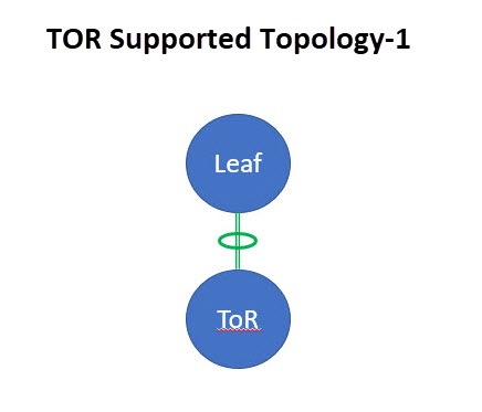
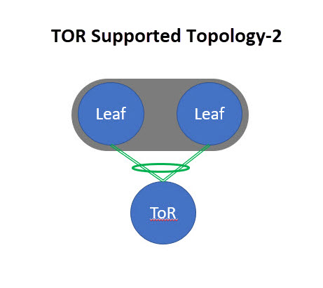
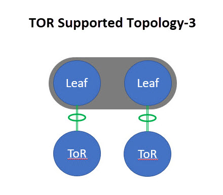
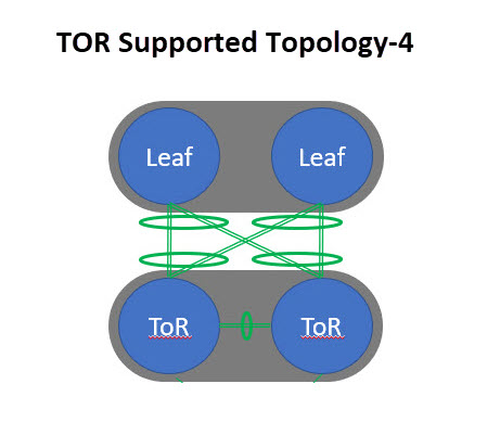
Unsupported topology for ToR switches
The following topology with ToR switches is not supported: ToR vPC pair connected to a single leaf switch.
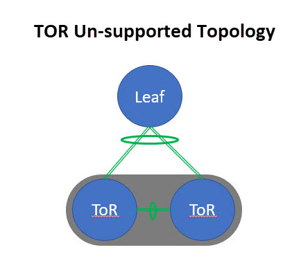
Configuring ToR switches
Create a fabric with a Data Center VXLAN EVPN template and add switches to the fabric, including switches used as ToRs. For more information, see Creating LAN and ACI Fabrics and Fabric Groups and Editing Data Center VXLAN Fabric Settings. Based on the selection of topology, perform any of the following steps:
Create leaf-ToR pairings
Perform the following procedure to configure a ToR and a leaf switch as shown in the ToR Topology-1 and 3, where ToR switch(s) are connected to leaf switch(s) through a port channel. For Topology-1 and 3, there is only one ToR and one leaf. Add switches used as ToR switches. For all four topologies, Nexus Dashboard only uses port channels in the ToR pairings.
-
Add ToR switches to the Data Center VXLAN EVPN fabric and set the role as ToR.
-
Navigate to the Switches page for the Data Center VXLAN EVPN fabric.
-
Choose Manage > Fabrics.
-
Click the Data Center VXLAN EVPN fabric in the Name column.
The Overview page for that fabric appears.
-
Choose Inventory > Switches.
-
-
In the Switches page, choose a ToR switch.
-
Click Actions > TOR Pairing.
The TOR Pairing page displays the ToR switches on the top horizontal bar and a list of potential pairing leaf switches below the ToR switches. The pairing status is displayed in the Details column.
Only one ToR switch is connected to a single leaf switch or a leaf switch in a vPC pair.
-
Click Save.
-
On the fabric Overview page, click Actions > Recalculate and deploy.
-
After the configuration deployment is completed on the Deploy Configuration page, click Close.
Perform the following procedure to configure a ToR and a leaf switch as shown in the ToR Topology-2 and 4. For Topology-2, a ToR switch is connected to leaf switches in a vPC pair. For Topology-4, vPC ToR switches are connected to the vPC leaf switches through back-to-back vPC connections.
-
Choose either of the vPC-paired leaf switches and click Actions > TOR Pairing. For more information on configuring vPC on ToR switches, see the "Create a vPC setup" section in Editing External Fabric Settings.
The TOR Pairing page appears with the list of ToR and vPC leaf switches.
-
Click Edit Pairing under the Action column.
-
Check the Enable <switch-name> Pairing as TOR Pairing check box.
-
Click Save.
-
On the fabric Overview page, click on Actions > Recalculate and deploy.
-
After the configuration deployment is completed on the Deploy Configuration page, click Close.
Unpair leaf-ToR pairings
Perform the following procedure to unpair the ToR switch.
-
Remove the overlay attachment before unpairing the ToR.
-
Navigate to the Switches page for the Data Center VXLAN EVPN fabric.
-
Choose Manage > Fabrics.
-
Click the Data Center VXLAN EVPN fabric in the Name column.
The Overview page for that fabric appears.
-
Choose Inventory > Switches.
-
-
Choose any leaf switch that has ToR pairing and click on Actions > TOR Pairing.
The TOR Pairing page appears with the list of paired switches.
-
Click Edit Pairing under the Action column.
-
Uncheck the Enable <switch-name> Pairing as TOR Pairing check box.
-
Click Save.
-
On the fabric Overview page, click Actions > Recalculate and deploy.
-
On the Deploy Configuration page, click Deploy.
-
After the configuration deployment is completed on the Deploy Configuration page, click Close.
Specifying a vPC/port-channel ID range and providing custom vPC/port-channel IDs for leaf-ToR pairing
With this feature, you can:
-
Configure a specific vPC/port-channel ID range for leaf-ToR pairing by enabling the Use Specific vPC/Port-Channel ID Range field. Nexus Dashboard then displays the vPC/Port-Channel ID Range field with the recommended vPC/port-channel ID range.
-
Edit a vPC/port-channel ID for paired switches by clicking the Action > Edit Pairing option on the TOR Pairing page.
Configure fabric settings for specifying a vPC/port-channel ID range for leaf-ToR pairing
-
Create a fabric with the Data Center VXLAN EVPN fabric and add ToR switches to the fabric.
For more information, see:
-
You need to use the same version of Cisco NX-OS when configuring your vPC switches.
-
On the fabric Overview page, choose the Data Center VXLAN EVPN fabric that you want to edit, and click Actions > Edit Fabric Settings.
-
Choose Fabric Management > vPC.
-
Put a check in the Use Specific vPC/Port-Channel ID Range check box to use a specific vPC/port-channel ID range for leaf-ToR pairing.
The vPC/Port-Channel ID Range field displays the recommended values.
The recommended values are from 1-499.
You can increase the existing range or add more ranges if the values are exhausted.
-
Specify a range for the vPC/Port-Channel ID Range field if you do not want to use the recommended values.
-
Click Save.
The new range applies to the new pairing.
Create leaf-ToR pairings
For configuring leaf-ToR pairings, see Configuring ToR switches and deploying networks in Data Center VXLAN EVPN fabrics and Configuring ToR switches.
Edit the leaf and the ToR port-channel IDs
-
Navigate to the Switches page for the Data Center VXLAN EVPN fabric.
-
Choose Manage > Fabrics.
-
Click the Data Center VXLAN EVPN fabric in the Name column.
The Overview page for that fabric appears.
-
Choose Inventory > Switches.
-
-
In the Switches page, choose the leaf switch you want to edit and click Actions > TOR Pairing.
The TOR Pairing page appears with a horizontal bar of the paired leaf switches.
-
Click Edit Pairing under the Action column.
The leaf page displays.
Check the Enable <switch-name> Pairing as TOR Pairing check box to enable leaf-ToR pairing.
-
Click the arrow on the right-hand corner of the page to view the fields.
-
In the Leaf Port Channel ID field, add or edit the existing ID value.
-
In the vPC ID field, add or edit the existing ID value.
-
In the ToR Port Channel ID field, add or edit the existing ID value.
-
Click Save.
If you have overlays attached to the paired switches, you cannot change the vPC/port-channel IDs.
-
Navigate to the Switches page and click Actions > Recalculate and deploy.
The Deploy Configuration page displays with the list of leaf switches.
After successful deployment, the Fabric Status column displays as In-Sync.
Deploy networks on ToR switches
To deploy networks on ToR switches in the Data Center VXLAN EVPN fabric, perform the following steps:
-
Choose Manage > Fabrics, then click the Data Center VXLAN EVPN fabric in the Name column.
The Overview page for that fabric appears.
-
Click Segmentation and security > Networks.
-
On the Networks page, select the networks that you want to deploy or create a new network.
For information about creating a network, see the section "Create networks for standalone fabrics" in Editing Data Center VXLAN Fabric Settings.
-
On the fabric Segmentation and security page, click Networks > Network attachments.
-
Select the leaf switches you want to edit and click on Actions > Edit.
The Edit Network Attachment page appears.
-
On the Edit Network Attachment page, choose Attach.
-
(Optional) You can enter a value in the VLAN field when you use Actions > Create to create a network, but not when you edit a network using Actions > Edit.
-
If a leaf is in a vPC pair, you can select interfaces/ports on a leaf switch and/or associated ToR(s), attach the ports, and click Save.
Port channels that are used to connect the ToR(s) toward the leaf switch(es) or vPC pairs are automatically updated with the required VLAN deployed in the server interfaces of the ToR switch.
-
Select the leaf switch and click on Actions > Deploy.
Configuring ToR switches and deploying networks in External fabrics
Overview
Nexus Dashboard supports Top-of-Rack (ToR) switches. You can add the Layer 2 ToR switches in an external fabric, and the ToR switches can be connected to the leaf switches in a Data Center VXLAN EVPN fabric. Typically, you connect the leaf and ToR switches with a back-to-back vPC connection. For more information, see Supported topologies for ToR switches.
Supported topologies for ToR switches
The following topologies with ToR switches are supported in Nexus Dashboard:
Cisco Nexus 7000 Series Switches do not support the ToR switch role in Cisco Nexus Dashboard.
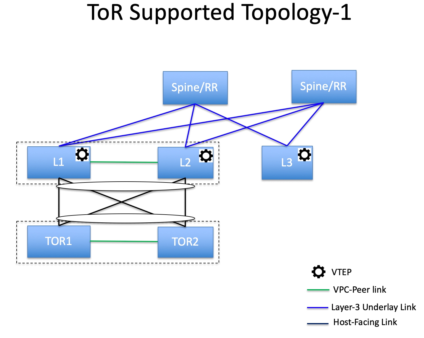
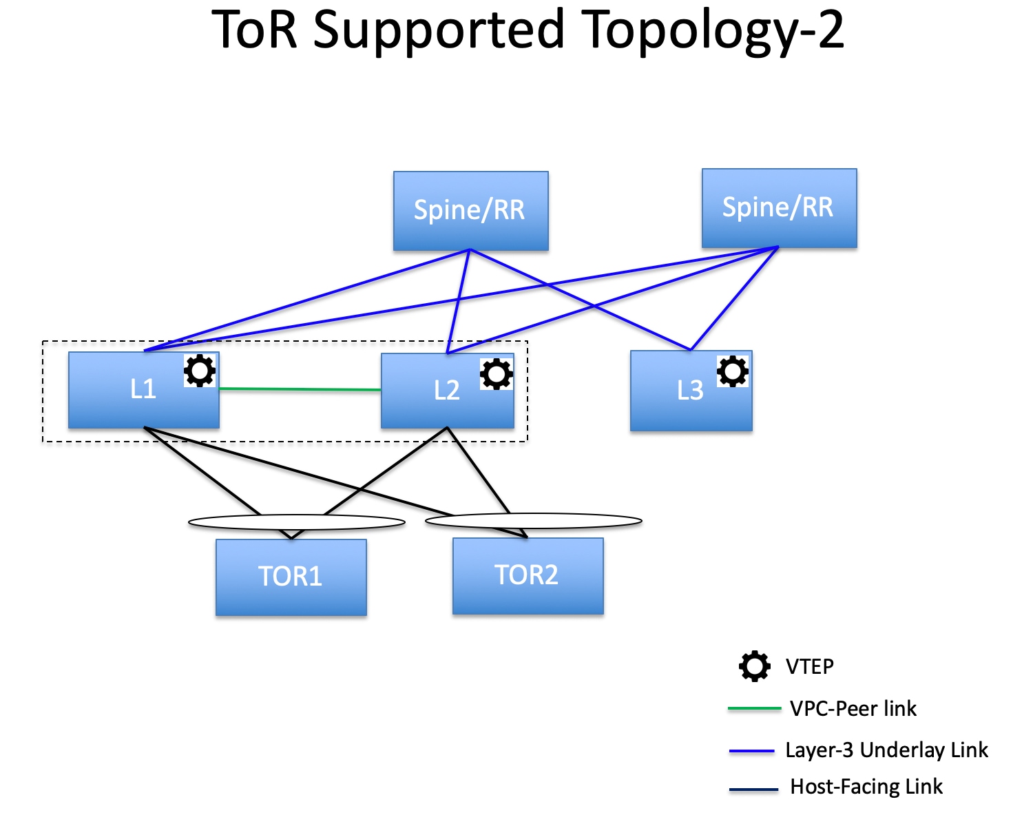
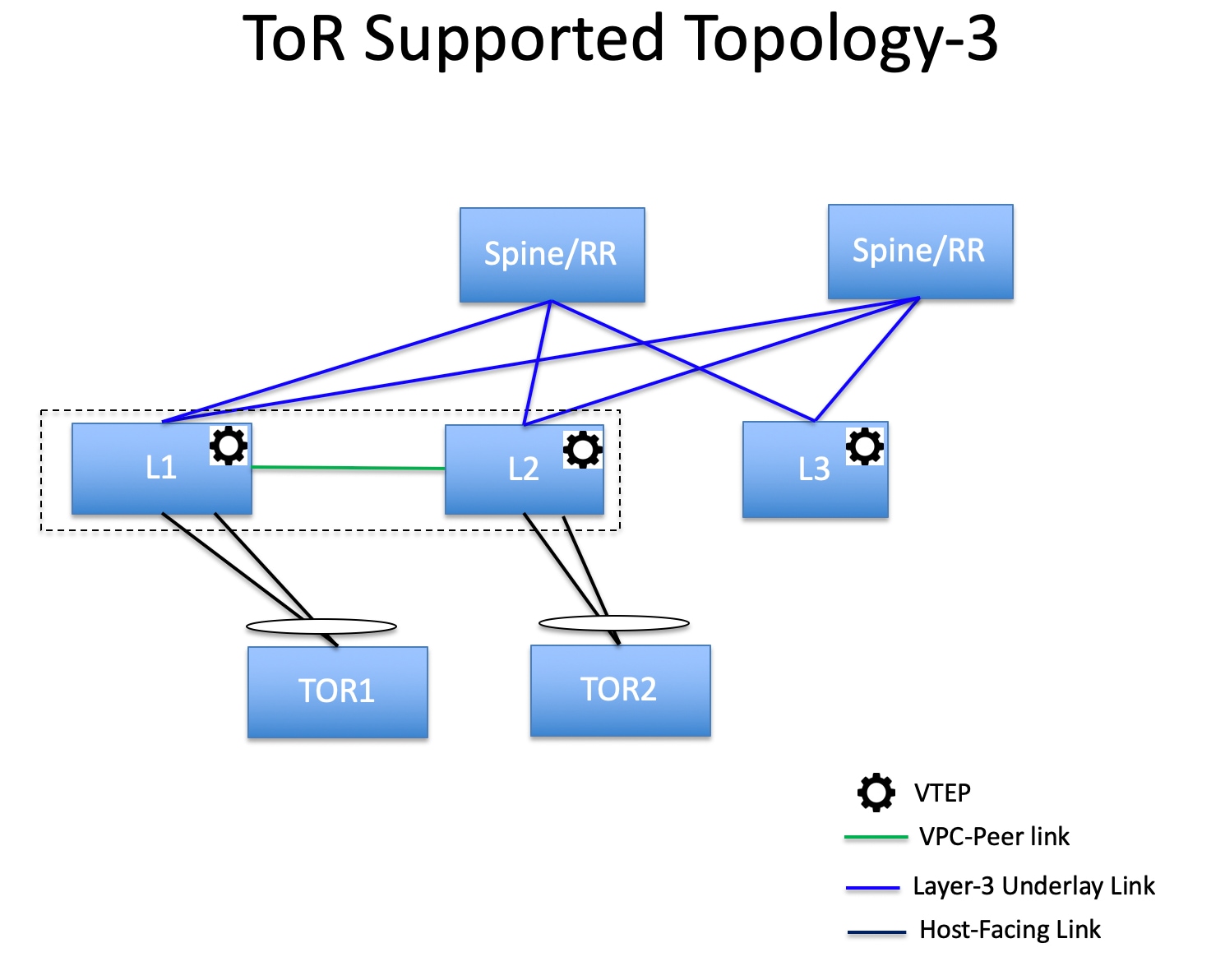
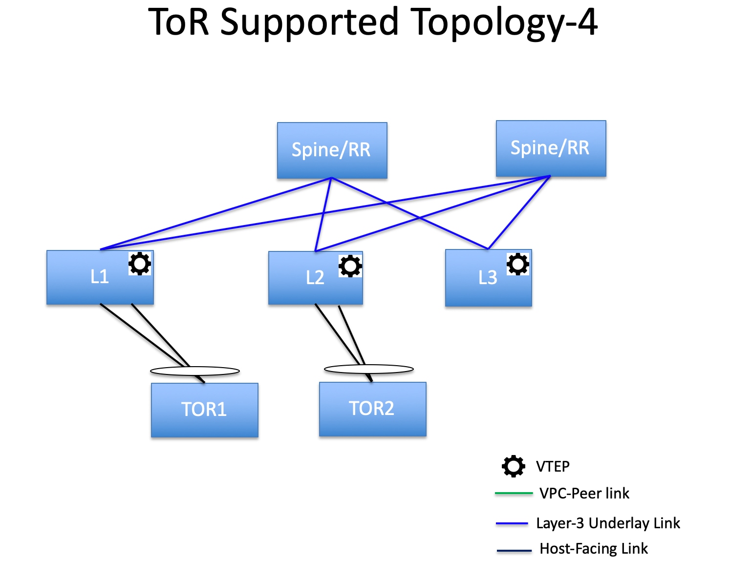
Unsupported topologies for ToR switches
The following topology with ToR switches is not supported in Nexus Dashboard:
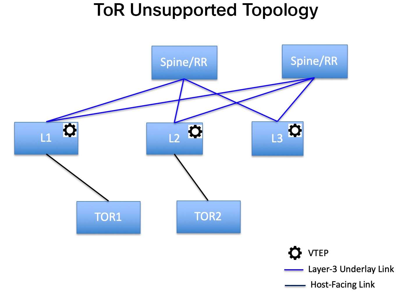
Configure ToR switches
Before you begin, make sure you have a Data Center VXLAN EVPN or create and deploy a new fabric. For more information, see Creating LAN and ACI Fabrics and Fabric Groups and Editing Data Center VXLAN Fabric Settings.
Nexus Dashboard supports the trunk_host policies for ToR switches. Make sure the ToR switch has a vPC and port channel policy attached on the interfaces connected to the leaf. These policies are used to connect the ToR switches in the external fabric to the leaf switches in the Data Center VXLAN EVPN fabric.
-
Create a Data Center VXLAN fabric and add two ToR switches.
The number of ToR switches can be more than two.
This procedure shows how to configure ToR switches as shown in the ToR Topology-1, where ToR switches are connected using a vPC.
The following are the different scenarios for connecting the ToR switches:
-
If a vPC is not configured on the ToR switches, then the vPC policy needs to be applied on the ToR-facing interfaces, if the uplinks for these ToR switches are connected to vPC leaf switches.
-
If ToR switches are connected to a leaf using a port channel, then port-channel policies need to be applied on the ToR interfaces connected to the leaf switches.
-
If ToR switches are connected to leaf switches as standalone, trunk policies need to be applied on the TOR interfaces.
-
While creating the Data Center VXLAN EVPN fabric, make sure that the Fabric Monitor Mode check box is not chosen.
-
The two ToR switches must be connected and have the same switch role.
-
After adding the ToR switches, make sure that the role for the ToR switches is ToR.
-
-
Select one of the ToR switches and click Actions > vPC Pairing.
-
Choose the second ToR switch as a vPC peer.
-
Under the vPC Pair Template, provide data for the relevant fields. Perform a Recalculate and deploy to generate a vPC configuration for the ToR switches.
For more information about all the fields and their descriptions, see the section "Create a vPC setup" in Editing External Fabric Settings.
Steps 2 and 3 are required since this example shows the ToR configuration for Topology-1. For Topology-2, -3, and -4, steps 2 and 3 are not required.
-
On the Switch Overview page, click Actions > Recalculate and deploy.
-
After the configuration is completed on the Deploy Configuration page, click Close.
-
Establish inter-fabric connectivity between two VXLAN EVPN fabrics.
See Connecting Multiple Fabrics for more information.
While establishing inter-fabric connectivity between the two VXLAN EVPN fabrics, under the General tab, choose the ToR Auto-deploy Flag check box.
This action enables automatic deployment of the networks and VRFs in the Data Center VXLAN EVPN fabric to the ToR switches in the VXLAN EVPN Multi-Site fabric when you click Recalculate and deploy in the VXLAN EVPN Multi-Site fabric. For more information, see Deploy networks on ToR switches.
-
Select the Data Center VXLAN EVPN fabric and click Actions > Interface.
-
Choose vPC and enter all the relevant details and click Save.
For more information about the fields on this page, see the section "Add interfaces" in Working with Connectivity for LAN Fabrics.
After saving all the information, click Deploy.
Follow the same steps to create a vPC on the ToR switch as well.
Deploy networks on ToR switches
To deploy networks on ToR switches in the external fabrics, you need to deploy them on the switches in the Data Center VXLAN EVPN through VXLAN EVPN Multi-Site. These switches should be connected to the ToR switches.
-
Choose Manage > Fabrics, then click the Data Center VXLAN EVPN fabric in the Name column.
The Overview page for that fabric appears.
-
Click Segmentation and security > Networks.
-
On the Networks page, choose the networks that you want to deploy or create a new network. For more information about creating a network, see Create networks for standalone fabrics.
-
Select the Network from the Network Attachment page. Click on Actions and Edit. Attach the network and select the appropriate interface/port-channels and then click on Save. These port channels connect the leaf switches to the ToR switches. The networks are deployed on these port channels.
-
On the fabric Overview page, click Actions > Recalculate and deploy.
Now the VLANs are deployed on the leaf switches.
-
Navigate to the interconnected VXLAN fabrics.
-
On the fabric Overview page, click Actions > Recalculate and deploy.
The networks created and deployed on the leaf switches in the Data Center VXLAN EVPN fabric are also deployed on the ToR switches in the external fabric. This step allows the same VLANs to be configured on the ToR switches that are deployed on the leaf switches in Step 4.
If VLANs are created on the ToR switches manually using the freeform configs, they are not modified.