
New and Changed Information
The following table provides an overview of the significant changes up to this current release. The table does not provide an exhaustive list of all changes or of the new features up to this release.
| Release Version | Feature | Description |
|---|---|---|
|
Nexus Dashboard 4.1.1 |
Improved fabric software navigation and workflow. |
Beginning with Nexus Dashboard 4.1.1, the navigation and workflow for fabric software in Nexus Dashboard have been enhanced. |
Understand Fabric Software for NX-OS and IOS-XE fabrics
This section provides detailed information for the Fabric Software feature in Nexus Dashboard for NX-OS/IOS-XE fabrics.
Fabric Software deploys Cisco software images to switches which allows network stability and feature consistency. The benefits of Fabric Software workflows include the following:
-
Comprehensive image management policies allow you to specify a version and patch level for a set of switches in a fabric
-
Nexus Dashboard validates compliance for the image policy associated with each switch in a fabric
-
Image staging, validation, and in-service software upgrade (ISSU) operations are independent, allowing mass upgrades and downgrades, and the ability to perform staging and validation in a single step
-
You can perform the following operations before the maintenance window:
-
Stage image files
This copies the image files to the switch bootflash.
-
Validate Network Operating System (NOS) and electronic programmable logic device (EPLD) compatibility where possible
This checks if the image is complete, if the image is valid for the individual hardware, and if the upgrade can be non-disruptive.
-
Run Update Analysis reports

-
Telemetry must be enabled on fabrics to run the pre-update or post-update analysis reports.
-
Stage & Validate is mandatory to run pre-update analysis report.
-
-
-
-
The ability to run reports and compare the results
-
The ability to generate snapshots of the pre or post updates
-
The View Logs column provides Live log status to monitor each operation
-
Allows you to make use of maintenance mode to minimize the impact of disruptive upgrades, especially for multi-reload upgrade situations
-
Upgrade groups allows bulk upgrades and downgrades. Upgrade groups have checks to avoid unnecessary downtime in redundant fabrics in the following cases:
-
Virtual Port Channel (vPC) peers are placed in different groups by default:
-
Switches that have even numbers or VPC role of primary
-
Switches that have odd numbers or VPC role of secondary
-
-
-
Provides visibility into previous and current upgrade details as well as high level summarization
-
Visibility into current NOS, EPLD and patch consistency at a switch, fabric, and group level
Navigate to the Fabric Software page for NX-OS and IOS-XE fabrics
To navigate to the Fabric Software page:
-
Click Manage > Fabric Software.
-
Click the NX-OS/IOS-XE tab.
Understand the information provided in the Fabric Software page for NX-OS and IOS-XE fabrics
The Overview tab provides upgrade and downgrade options at fabric-level whereas the Devices tab provides these options at an individual device or switch-level.
The Overview tab displays the images, policies, platforms, release versions, and fabric information.
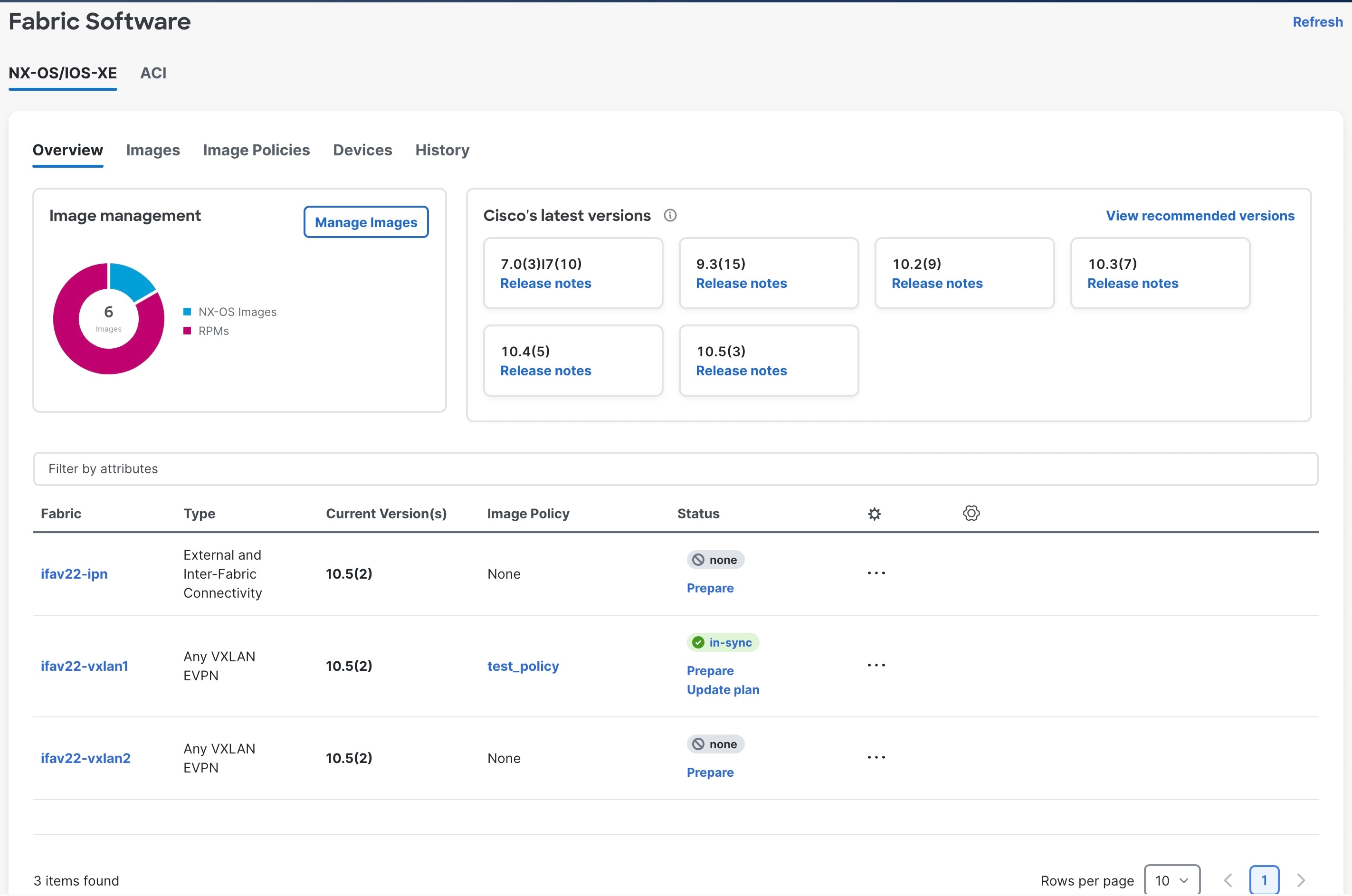
The Fabric Software page has the following functional areas:
-
Overview: This displays the images, policies, platforms, release versions, and fabric information.
-
The Image management card displays the number of images and the type of packages or patches.
-
The Cisco’s latest versions card displays the latest versions of the switch software that are available, the versions of the switch software that Cisco recommends, and the corresponding release notes.
-
The fabric area displays information about the configured fabrics.
-
|
Field |
Description |
|
Fabric |
The name of the fabric. |
|
Type |
The type of fabric. |
|
Current version(s) |
The current versions of software running on the switches in the fabric. |
|
Image policy |
The fabric-level image policy that is being used for the switches in the fabric, if applicable. See Upgrade or downgrade switches in a fabric under Overview tab for more information. |
|
Status |
The status of the fabric-level image policy:
|
-
Images: This displays the images. You can upload or delete images.
|
Field |
Description |
|
Platform |
Specifies the name of the platform. Images, RPMs, or SMUs are categorized as follows:
The images are the same for N9K and N3K platforms. The platform is Other if the uploaded images are not mapped to any of the existing platforms. The platform is N9K/N3K for RPMs. |
|
Bits |
Specifies the bits of the image |
|
Image Name |
Specifies the filename of the image, RPM, or SMU that you uploaded. |
|
Image Type |
Specifies the file type of the image, EPLD, RPM, or SMU. |
|
Image Sub Type |
Specifies the file type of the image, EPLD, RPM, or SMU. The file type EPLDs are epld. The file types of images are nxos, system or kickstart. The file type for RPMs is feature and for SMUs the file type is patch. |
|
NOS Version |
Specifies the NX-OS or IOS-XE image version for only Cisco switches. |
|
Size (Bytes) |
Specifies the size of the image, RPM, or SMU files in bytes. |
|
Reference Count |
Specifies the number of image policies this image is part of. |
|
Image Present |
Determines if the uploaded image is present after a successful Nexus Dashboard restore process and/or Nexus Dashboard upgrade process.
Switch firmware images that were uploaded to Nexus Dashboard in release 3.2.x will not be carried over when you upgrade to Nexus Dashboard 4.1.1 and will not appear in the Image Present column. After upgrading to Nexus Dashboard 4.1.1, re-upload those switch firmware images. See Upload the image to Nexus Dashboard for more information. |
|
Checksum |
Specifies the checksum of the image. The checksum checks if there’s any corruption in the file of the image, RPM, or SMU. You can validate the authenticity by verifying if the checksum value is same for the file you downloaded from the Cisco website and the file you upload in the Image Upload. |
-
Image policies: This displays the image policies. You can create, delete, or edit image policies.
|
Field |
Description |
|
Policy Name |
Specifies the name of the image policy. |
|
Platform |
Specifies the name of the platform. Images, RPMs, or SMUs are categorized as follows:
The images are the same for N9K and N3K platforms. The platform is Other if the uploaded images are not mapped to any of the existing platforms. The platform is N9K/N3K for RPMs. |
|
NOS Version |
Specifies the NX-OS or IOS-XE image version for Cisco switches only. |
|
Image Name |
Specifies the filename of the image, RPM, or SMU that you uploaded. |
|
EPLD Name |
Specifies the name of the electronic programmable logic device (EPLD). |
|
Package Name(s) |
Specifies the name of the package. |
|
Disable RPM(s) |
Shows whether the RPM/SMU Disable option is enabled (true) or not (false). |
|
Reference Count |
Specifies the number of switches this policy is assigned to. |
|
Image Present |
Determines if the uploaded image is present after a successful Nexus Dashboard restore process or Nexus Dashboard upgrade process. |
|
Policy Description |
Specifies a description of the image policy. |
-
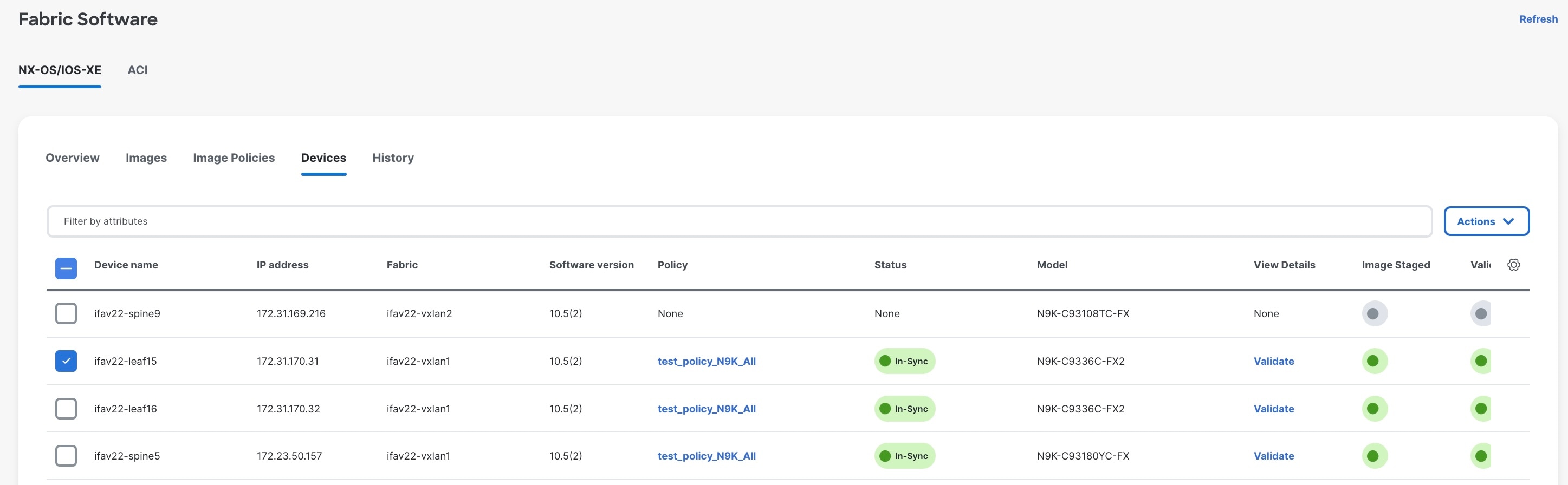
Devices: This displays the devices. You can stage image, upgrade, validate, change mode, attach group, detach group, attach policy, or detach policy.
You cannot attach or detach fabric policies from the Devices tab. Only image policies can be attached or detached from the Devices tab.
|
Field |
Description |
|
Device name |
Specifies the name of the device. |
|
IP address |
Specifies the IP address of the device. |
|
Fabric |
Specifies the fabric that the device resides in. |
|
Software version |
Specifies the NX-OS or IOS-XE image version for Cisco switches only. |
|
Policy |
Specifies the image policy that is being used by the device. |
|
Status |
Specifies the configuration status. Status will either be In-Sync or Out-of-sync. |
|
Model |
Specifies the switch model. |
|
View Details |
Click the link to view details for the switch, if available. For example, click Compliance to view the compliance check details. |
|
Image Staged |
Specifies whether the image has been staged or not. |
|
Validated |
Specifies whether the image has been validated or not. |
|
Upgraded |
Specifies whether the image has been upgraded or not |
|
Update Groups |
Specifies the name of the upgrade group. |
|
Mode |
Specifies the upgrade mode (Maintenance or Normal). |
|
vPC Role |
Specifies the VPC role, if applicable (Primary or Secondary). |
|
vPC Peer |
Specifies which switch is the VPC peer with this switch, if applicable. |
|
Role |
Specifies the role for the switch. |
|
Last Upgrade Action |
Specifies when the last upgrade was performed on the switch. |
-
History: This displays the history of all the operations performed on the switches.
|
Field |
Description |
|
ID |
Specifies the ID number. |
|
Device Name |
Specifies the device name. |
|
Version |
Specifies the version of the image on the device. |
|
Policy Name |
Specifies the policy name attached to the image. |
|
Status |
Displays if the operation was a success or failure. |
|
Reason |
Specifies which action was performed. |
|
Operation Type |
Specifies the type of operation performed. |
|
Fabric Name |
Specifies the name of the Fabric. |
|
Created By |
Specifies the user name who performed the operation. |
|
Timestamp |
Specifies the time when the operation was performed. |
Terminology
This describes the terms that you must be familiar with:
|
Term |
Acronym |
Description |
|
Electronic Programmable Logic Device |
EPLD |
The EPLD image upgrades to enhance hardware functionality or to resolve known issues. |
|
In-Service Software Upgrade |
ISSU |
ISSU allows you to upgrade the software version of the release on a chassis device with no network downtime. |
|
Local Area Network |
LAN |
LAN consists of a series of computers linked together to form a network in a circumscribed location. |
|
Network Operating System |
NOS |
A specialized operating system designed for a network device such as a router, switch or firewall. Some examples include NX-OS for Nexus switches, IOS XE for Cisco Catalyst switches and so on. |
|
Rendezvous Points |
RP |
RP is a router that acts as the place where sources and receivers of multicast data can find each other. |
|
Route Reflector |
RR |
Route Reflector is a router that acts as a routing information exchange server for all other iBGP routers. |
|
Storage Area Network |
SAN |
SAN refers to the Storage Area Network management and analytics capabilities provided by the SAN Controller persona in Nexus Dashboard. This includes comprehensive management, monitoring, and visualization of SAN fabrics, typically composed of Cisco MDS switches supporting Fibre Channel SAN traffic. |
|
Secure Copy |
SCP |
SCP is used by fabric software to transfer files between devices. |
|
Secure File Transfer Protocol |
SFTP |
SFTP is a network protocol that allows you to securely access, transfer, and manage large files and sensitive data. |
Required software versions
For Cisco Nexus Dashboard services compatibility information, see the Cisco Data Center Networking Applications Compatibility Matrix.
Prerequisites
This section describes the prerequisites. This document assumes that the reader has a fundamental knowledge of Nexus Dashboard.
-
SCP is used by Fabric Software. Both SCP and SNMP are always enabled by default and a minimum of 2 external service pool IPs are needed when you enable the Nexus Dashboard.
-
Ensure that your user role is network-admin or device-upg-admin.
-
Ensure that there is a fabric, the fabric must have the "Deployment Enabled" flag set, and the switches are managed by the Nexus Dashboard in this fabric.
-
Ensure you have LAN credential set.
Guidelines and limitations
This section describes the guidelines and limitations.
-
Nexus Dashboard has a 12 GB limitation for virtual Nexus Dashboards (vNDs) and physical Nexus Dashboards (pNDs) for image management images and a limitation of 16 GB total space (with the rest being used by other features on Nexus Dashboard) for total images stored under Manage > Fabric Software > Images, as described in Upload the image to Nexus Dashboard. If you reach the space limit for images in Nexus Dashboard, navigate to Manage > Fabric Software > Images, choose the images that are no longer needed and click Actions > Delete.
-
There is a known issue where Nexus Dashboard is not able to stage or copy an IOS-XE image to Catalyst 9000 switches running IOS-XE 17.12.2 or later, where the image upgrade fails at the SCP image copy point of the process with this error:
Error opening scp://<ND-IP-address>/scp_data/<bin> (Undefined error)
This issue occurs because IOS-XE 17.10.x and later enables ETM (Encrypt-then-MAC) SSH algorithms only by default, whereas the Nexus Dashboard SCP client will attempt the upgrade using non-ETM MAC algorithms, leading to a
no matching mac foundfailure.The workaround for this issue is to push the following configuration to the switch using the freeform configuration in Nexus Dashboard:
ip ssh client algorithm mac hmac-sha2-256 hmac-sha2-256-etm@openssh.com hmac-sha2-512 hmac-sha2-512-etm@openssh.com
For more information on freeform configurations, see "Deploy freeform CLIs on a specific switch" in Configuring Switches for LAN and IPFM Fabrics
-
Fabric Software for the SAN Controller persona does not support NPE images.
Upgrade or downgrade switches in a fabric under Overview tab
You can perform switch upgrades or downgrades at the fabric level.
This feature applies only to LAN and IPFM fabrics.
Prepare a fabric image policy
This section describes how to prepare a software image policy that can be used at the fabric level.
-
Navigate to the Fabric Software page for NX-OS and IOS-XE fabrics.
-
In the Fabric Software page, verify that the Overview tab is selected.
See Understand Fabric Software for NX-OS and IOS-XE fabrics for more information on the Overview tab and the other tabs in the Fabric Software page.
-
In the list of fabrics shown in the Overview page, locate the fabric where you want to prepare a software image policy that will be used for that fabric.
-
In the Status column, click Prepare in the row for the fabric where you want to prepare a software image policy.
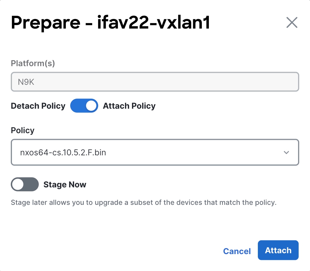
The Prepare dialog box appears.
-
In the Prepare dialog box, make the appropriate configurations for this fabric-level image policy.
-
Review the types of devices listed in the Platform(s) area.
The list will consist of device types that are detected in this fabric. Use this list to verify that the software policy that you select in the next step aligns with the type of devices that you have in this fabric.
For example, if you see
CAT9K,N9Klisted in the Platforms area, when you select the policy in the next step, you would want to verify that any policy that you select aligns with either Catalyst 9000 or Nexus 9000 series switches. -
Click the radio button to either Attach Policy or Detach Policy.
-
If you select Detach Policy, click Detach to detach the fabric-level image policy from these switches in this fabric.
-
If you select Attach Policy, proceed with the instructions below to attach an existing image policy or to create a new one.
-
-
In the Policy drop-down list, attach an existing image policy or create a new one.
-
If you already have fabric-level image policies created and you want to use one of those existing image policies, scroll through the list of image policies and select the one that you want to use. Then, proceed to Step 5d.
-
If you do not have any fabric-level image policies created yet, or if you do not want to use one of the existing image policies for any reason, click +Create Policy.
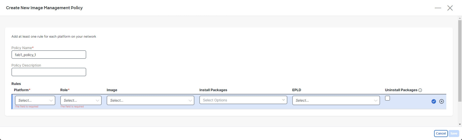
The Create New Image Management Policy page appears.
-
In the Create New Image Management Policy page, enter a unique name for the fabric-level image policy in the Policy Name field or leave the automatically-generated policy name as-is, if desired.
-
Enter a description for the new fabric-level image policy in the Policy Description field, if necessary.
-
In the Rules area, click +Add Row.
-
Enter the necessary information in the Rules area to configure this new fabric-level image policy.
-
Platform: Select the types of switches in the fabric that will use this new fabric-level image policy.
-
Role: Select the roles for the switches in the fabric that will use this new fabric-level image policy.
-
Use one of the following options to be used with this new fabric-level image policy:
-
Image: Select the software image that will be used with this new fabric-level image policy.
-
Install Packages: Select the installation packages that will be used with this new fabric-level image policy.
-
EPLD: Select the electronic programmable logic device (EPLD) image that will be used with this new fabric-level image policy.
-
-
Uninstall Packages: Check the box to uninstall packages from the switches in the fabric as part of this new fabric-level image policy.
-
-
Click the checkbox in the row to complete the configuration for this image policy rule.
-
Repeat these steps to configure a new set of rules for this fabric-wide image policy, if necessary.
For example, you might configure a new set of rules with a different option in the Platform field selected to configure a new set of rules for other types of switches in the fabric, or with a different option in the Role area selected to configure a new set of rules for switches with a different role in the fabric.
-
Click Save when you have configured all the necessary rules in the fabric-level image policy.
You are returned to the Prepare - <fabric> page, with this new fabric-level image policy automatically selected in the Policy field.
-
-
-
Determine when you want to stage the fabric-level image policy.
-
Leave the Stage Now option unselected to stage the fabric-level image policy at a later date.
Staging the fabric-level image policy later allows you to stage the images in the fabric to be used later (for example, by copying the images onto the switch bootflash) so that you can upgrade a subset of the devices later that match the policy.
-
Click the Stage Now option to enable this option.
The fabric-level image policy will stage after you click Attach in the next step.
-
-
Click Attach.
The image policy is now attached to this fabric, and is displayed in the Image Policy column in the Overview page.
-
-
Make additional configurations for each fabric, if necessary, based on the status shown in the Status column:
-
None: No fabric-level image policy has been configured for this fabric.
-
In-Sync: The current image versions on each switch in the fabric is in-sync with the expected image versions. No further configurations are needed for the fabric-level image policy for this fabric.
-
Out-of-Sync: The current image versions on one or more switches in the fabric is out-of-sync with the expected image versions. Click the Out-of-Sync text in the Status column to bring up a slide-in pane that shows which switches in the fabric are out-of-sync with the expected image versions. See Recalculate compliance for more information.
-
Prepare: Click to prepare a software image policy that can be used at the fabric level, as described in this section (Prepare a fabric image policy).
-
Update plan: The system is ready to apply software updates to the appropriate switches in the fabric. Click Update plan to bring up the Software Update Plan for the fabric. See Install or upgrade software on devices in a fabric for more information.
-
Once you have prepared a software image policy that will be used for a fabric, you cannot then delete or edit that policy directly. However, you can delete uploaded images, even if the ref count is greater than 0.
If uploaded images are used in a software image policy but you have not attached that software image policy to any devices yet, then you can delete those software image policies along with the selected images. However, if you created multiple software image policies using one image and you attached one of those policies to devices in a fabric, then you cannot delete the image and you cannot delete any of the other software image policies that use that image, even if those software image policies are not attached to any devices in the fabric yet.
Change number of concurrent switches for staging/validating/updating
As you go through the procedures in Install or upgrade software on devices in a fabric, there are points during the staging/validating or updating processes where you might be taking actions on a group of switches concurrently. Following are the default values for the number of switches that are grouped together when you are taking an action on a group of switches concurrently:
-
Staging/validating: Default number of switches is 10
-
Updating: Default number of switches is 20
Follow these procedures if you want to change these default values.
-
Navigate to Admin > System Settings > Fabric management.
-
In the Advanced Settings area, click the Admin tab.
-
Modify the values in the following fields, if necessary:
-
Image update thread pool size: The number of switches that can be updated concurrently.
Default value is 20. Valid range is 10-200.
-
Image stage/validate thread pool size: The number of switches that can be staged and validated concurrently.
Default value is 10. Valid range is 5-200.
-
-
Click Save when you have completed any configuration changes on this page.
Install or upgrade software on devices in a fabric
This section describes how to install or upgrade software on the devices in a fabric using a fabric-level image policy.
-
Navigate to the Fabric Software page for NX-OS and IOS-XE fabrics.
-
In Fabric Software, verify that Overview is selected.
-
In the list of fabrics shown in the Overview page, locate the fabric where you want to install or upgrade software on the devices in that fabric.
-
In the row for a fabric, select Update plan in the Status column to install or update the software on the devices in that fabric.
You will see the Update plan option only after you prepare the fabric.
To prepare the fabric:
Click Prepare in the Status column of the fabric that you want to install or upgrade.
The Prepare - Fabric Name dialog box opens.
-
The platform name is chosen by default in the Platform(s) field.
-
In the Policy field, select a policy that you want to attach to the fabric.
-
Click Attach to create an update plan.
You can also stage and run pre-update analysis from here.
-
-
After you prepare the Fabric, in the Fabric Software page, select Update plan in the Status column to install or update the software on the devices in that fabric.
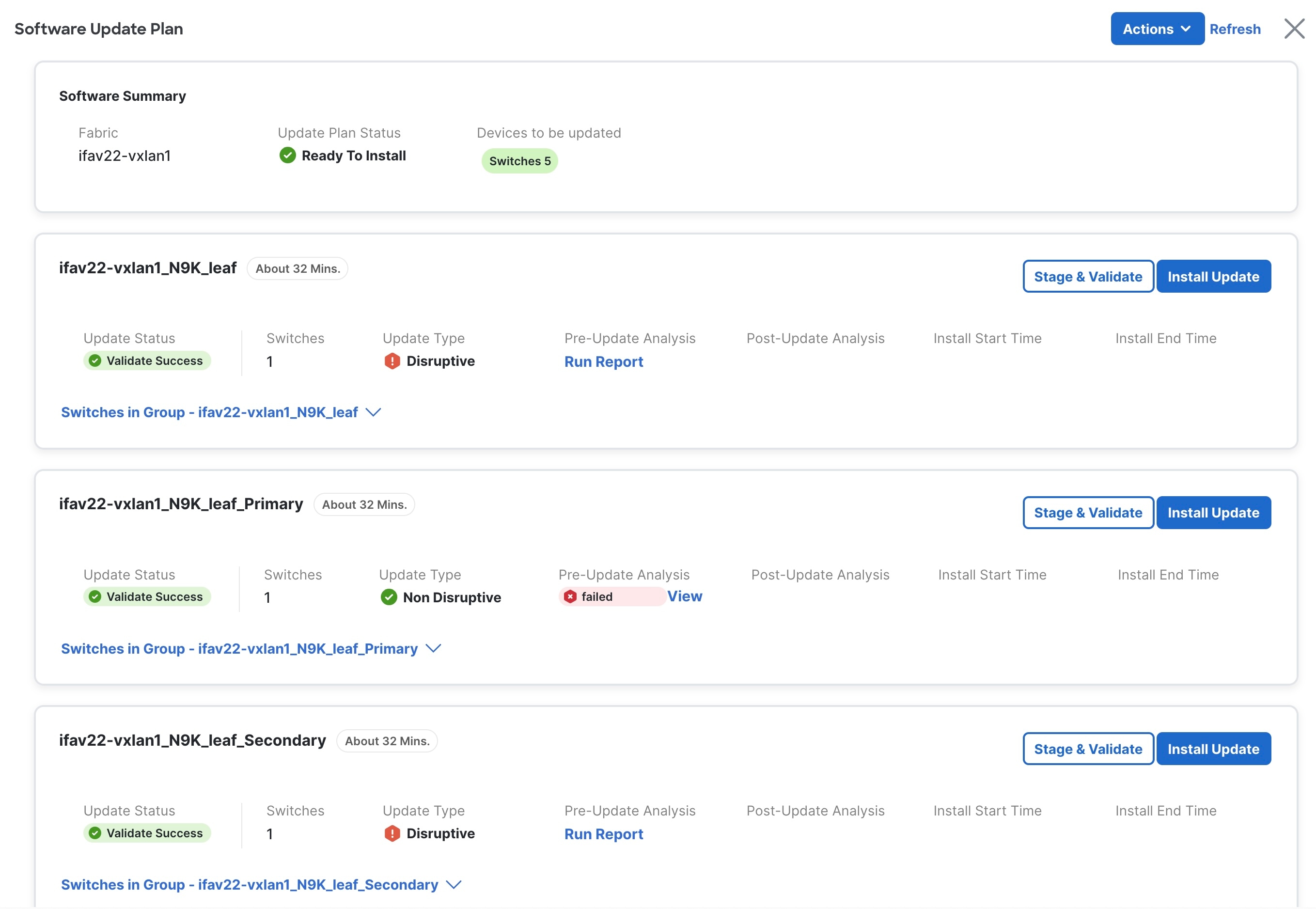
The Software Update Plan page appears.
-
Determine if you want to automatically assign groups. By default, switches will be assigned groups based on their roles.
To automatically assign groups, click Actions> Auto-Assign Groups.
You can automatically assign groups based on the following criteria:
-
Role Based: All switches of a given role for a fabric in the same group
-
Even Odd: Switches that are grouped in odd or even groups:
-
Switches that have even numbers or vPC role of primary
-
Switches that have odd numbers or vPC role of secondary
Nexus Dashboard uses the following calculations to balance the number of switches in the even and odd groups as much as possible:
-
Nexus Dashboard will first divide the switches by role between the even and odd groups; this is done to reduce the likelihood of having most or all of one type of switch in only one of the two groups.
-
Nexus Dashboard will then alternate switch assignments between the even and odd groups, where the first switch of one type goes into the even group, the second switch of that same type goes into the odd group, and so on.
-
-
-
-
Review the information provided in the Software Summary area.
-
Fabric: The name of the fabric where you will be installing or upgrading software on the devices in that fabric.
-
Update Plan Status: The status of the update plan.
-
Devices to be Updated: The number of devices in this fabric that will be updated.
-
-
Review the general information provided in the update group area.
-
Next to the update group name, the approximate time needed to update all the switches in the group is displayed.
-
Switches: Shows the number of switches in this switch group.
-
Update Status: Shows the status of the update.
-
Update Type: Shows the nature of update.
-
Pre-update Analysis: Shows if any warnings are triggered prior to the update. This is applicable only for telemetry-enabled fabrics.
You can also Run Report and view the pre-update analysis. The Run Report button is enabled only after Stage & Validate is completed.
-
Post-update Analysis: Shows if any warnings are triggered after the update. This is applicable only for telemetry-enabled fabrics.
-
Install Start Time: Shows the time when the update installation started.
-
Install End Time: Shows the time when the update installation ended.
-
-
Review the more detailed information provided in the switch group area.
Click the down arrow next to the switch group name to display more detailed information on that switch group.
Field
Description
Switch
The switch that belongs to this switch group. Click the switch name to bring up additional information on that switch.
IP Address
The IP address for a switch in the switch group.
Model
The model of the switch in the switch group.
Role
The role of the switch in the switch group
Current Software
The current level of software running on this switch in the switch group.
Update Type
The update type for this switch in the switch group.
Update Status
The update status of this switch in the switch group.
Logs
The install logs for this switch in the switch group. Click View Logs for additional information on the install log.
Mode
The mode for the switch in the switch group. The available modes are Normal, Maintenance, and Inconsistent.
vPC Role
The vPC role of the switch in the switch group, if applicable.
vPC Peer
The vPC peer of the switch in the switch group, if applicable.
Policy
The policy associated with this switch in the switch group. Click the policy hyperlink for additional information.
Last Upgrade Action
The last upgrade action for this switch in the switch group.
-
Determine if you want to make changes to the switches in the update group.
For each of the actions listed below, you can click the box next to single switch in the update group or click the box next to Switch to select all the switches in the update group. The following options are then displayed above the update group:
-
Remove from Update Group: Click to remove the selected switch(es) from the update group. Such switches fall under group "None".
-
Create New Update Group: Click to create a new update group with the selected switch(es).
-
Move to Update Group: Click to move the selected switch(es) to a different update group.
-
-
To upgrade the switches in an update group, perform the following steps in that group’s area in the Software Update Plan page:
The default number of switches that you can stage and validate concurrently is 10, and the number of switches that you can update concurrently is 20. To change the default values, see Change number of concurrent switches for staging/validating/updating.
-
Click Stage & Validate to stage and validate the update. This step downloads the NX-OS image on the switch and performs a compatibility check before installing the update.
It is preferred to perform staging first, as it will perform compatibility checks on the switch before installing updates.
-
Run pre-update analysis report and view its details. The report can also be re-run.
The Re-run button will not be listed after the install update is successful.
-
Click View Logs to view the actions that take place on the NX-OS switches as they relate to Nexus Dashboard.
The Post-update report for Switches page appears.
-
Click Install Update to perform the software update on the switches in this update group.
Install Update allows you to trigger a software upgrade for all the switches in that update group.
Check the Update Status in the Update group area before clicking Install Update. If the update status is "failed", the Install Update button will still be available but should not be clicked.
The Install Update dialog box opens. It provides the following details:
-
Switches: Switches in an update group
-
Minimal Device Impact: Shows either Disruptive or Non-disruptive based on the compatibility check done as part of validation.
-
Estimated Update Time: Shows approximate time needed to update all the switches in the group
-
The number of switches that are in an update group. By default, updates are performed concurrently on 20 switches at a time, so if you have 40 switches in an update group, updates are first performed on the first batch of 20 switches, and then a second pass is performed on the second batch of 20 switches.
-
Advanced options that are described in the next step, which may change the estimated timeframe, depending on the advanced options selected.
-
In the Execution paradigm field, select a Serial or Parallel execution:
-
Serial: Switches are updated one at a time, serially, where the update process must fully complete on one switch before it begins on the next switch in the update group.
-
Parallel: Switches are updated all at one time, depending on the number of switches that can be updated concurrently. For example, if you have 40 switches in the update group but 20 switches are updated at a time concurrently, then a Parallel setting will result in the first set of 20 switches going through the update process, all at one time, and then the second set of 20 switches going through the same concurrent update process after the update process has completed for the first set.
-
-
In the Snapshot drop-down, choose one of the following options: No analysis, Use existing pre-analysis, Snapshot, or Full analysis.
-
The Use existing pre-analysis and Full analysis options are only available when the Telemetry option is enabled for the fabric. See Creating LAN and ACI Fabrics and Fabric Groups for more information.
-
The snapshot option is essentially a reporting mechanism to compare the state of the system before and after an upgrade; the snapshot option in this case is not used to create a checkpoint (snapshot) of the system. See Snapshots for more information about this option.
-
-
-
Make the proper selection in the Installation Type field, if necessary. You can choose between Disruptive or Non-Disruptive.
If you choose Non-Disruptive, then the Use Maintenance Mode checkbox will be cleared automatically.
When you click Stage & Validate earlier in these procedures, Nexus Dashboard will determine if the switches in the update group are set with disruptive or non-disruptive upgrade settings.
Refer to Understanding In-Service Software Upgrades for more information about this option.
-
Check the box next to Use Maintenance Mode if you want to enable this option.
Maintenance mode, along with normal mode, are part of Graceful Insertion and Removal, or GIR. When the Maintenance Mode option is enabled, Nexus Dashboard will place the switches in the update group in the maintenance mode during the update process, where all configured Layer 3 control-plane protocols are isolated from the network, and will return the switches to normal mode after the update process is completed. Refer to Configuring Graceful Insertion and Removal for more information on GIR.
-
In the Error handling/On failure field, determine if you want the installation to Continue or to Pause if there is a failure that occurs during the update. A failure might occur for a number of reasons, such as a switch failing to come back online or a failure to successfully establish an ssh session between Nexus Dashboard and the switch.
The actions taken with this setting may also be affected by settings in other areas.
For example, assume that you have Pause as the setting for this field, and you have Serial as the setting in the Execution Paradigm field. If a set of 20 switches in an update group are going through a serial update and an issue arises with the sixth switch in the set, the update will pause at that sixth switch’s update process and will not proceed with the update process for the remaining 14 switches in the set until you manually begin the update process again.
However, if you have Parallel as the setting in the Execution Paradigm field and there is an issue with the sixth switch in a set in the update group, the update process will complete for the other 14 switches in the set that are being updated concurrently, and the update process will pause before moving to the update process for the next set of switches in the update group.
-
-
Once Install Update is complete with full analysis or use existing analysis option, post-update analysis report is generated.
In some cases, the Post-update report for Switches page does not accurately display the correct information for the switches. This might happen due to a timing issue, such as when the version is getting updated in the telemetry pipeline at the same time as the post upgrade is being triggered. Wait for around 10 minutes, then click Rerun report in the Post-update report for Switches page to address this issue. You can also verify the telemetry data availability by checking the telemetry status at Admin > System Status > Telemetry > Telemetry Status.
-
Recalculate compliance
This section describes how to recalculate compliance on devices in a fabric where software was installed or upgraded using a fabric-level image policy.
The Recalculate compliance option checks if the versions on the switch and the policy are same. You might want to recalculate compliance when the information on the Overview page does not correctly reflect the expected status for the devices in a fabric or to change the Status from Out-of-Sync to In-Sync. If you made a change directly on the switch CLI, you might also use the Recalculate compliance option so that the system fetches those updates from the switch and compares them with those in the fabric policy rules.
-
Navigate to the Fabric Software page for NX-OS and IOS-XE fabrics.
-
In the Fabric Software page, verify that the Overview tab is selected.
-
In the list of fabrics shown in the Overview page, locate the fabric where you want to recalculate compliance on the devices in that fabric.
-
In the row for that fabric, click the ellipsis (…) at the end of that row, then select Recalculate compliance.
The status provided in the Status column might get updated to In-Sync or Out-of-Sync, based on a comparison between the switch CLI and the fabric policy. Click on the status entry to show additional in-sync or out-of-sync details.
Upgrade or downgrade individual switch or a group of switches under Devices tab
This section provides detailed information for the Fabric Software feature in Nexus Dashboard for NX-OS/IOS-XE fabrics.
Fabric Software deploys Cisco software images to switches which allows network stability and feature consistency. The benefits of Fabric Software workflows include the following:
-
Comprehensive image management policies allow you to specify a version and patch level for a set of switches
-
Nexus Dashboard validates compliance for the image policy associated with each switch
-
Image staging, validation, and in-service software upgrade (ISSU) operations are independent, allowing mass upgrades and downgrades, and the ability to perform staging and validation in a single step
-
You can perform the following operations before the maintenance window:
-
Recalculate compliance
The Recalculate compliance option checks if the versions on the switch and the policy are same.
-
Stage image files
This copies the image files to the switch bootflash.
-
Validate Network Operating System (NOS) and electronic programmable logic device (EPLD) compatibility where possible
This checks if the image is complete, if the image is valid for the individual hardware, and if the upgrade can be non-disruptive.
-
Run reports
-
Modify groups
-
Generate snapshot
-
-
-
The ability to run reports and compare the results
-
The ability to generate snapshots of the pre/post updates
-
The View Details column provides Live log status to monitor each operation
-
Allows you to make use of maintenance mode to minimize the impact of disruptive upgrades, especially for multi-reload upgrade situations
-
Upgrade groups allows bulk upgrades and downgrades. Upgrade groups have checks to avoid unnecessary downtime in redundant fabrics in the following cases:
-
Virtual Port Channel (vPC) peers are placed in different groups by default:
-
Switches that have even numbers or VPC role of primary
-
Switches that have odd numbers or VPC role of secondary
-
-
-
Provides visibility into previous and current upgrade details as well as high level summarization
-
Visibility into current NOS, EPLD and patch consistency at a switch, fabric, and group level
To upgrade switches from the Devices tab, follow the below sequence:
-
Upload image
-
Create image policies
-
Attach image policy to switches
-
Stage image
-
Validate image
-
Run pre-ISSU reports
-
Upgrade switches
-
Run post-ISSU reports
You have two upgrade methods and one downgrade method:
-
Disruptive upgrade or downgrade: During the upgrade or downgrade process the switches go down temporarily, which results in a disruption in your fabric traffic.
For more information, see Upgrade or downgrade switches.
-
Non-disruptive upgrade: This allows the switches to run without disruption in your fabric traffic.
-
Non-disruptive downgrade: Not supported.
Upgrade or downgrade switches
This section describes both the disruptive and non-disruptive method of upgrading or downgrading a group of switches.
Guidelines and limitations: Disruptive upgrade
-
If you are downgrading a group of switches, the process is identical to the process for upgrading a group of switches, except that the target image that you choose will be earlier than the currently installed image. The text for dialogs, fields, buttons, and other controls in the UI specify “upgrade” even though you are downgrading the software.
-
For switches running on NX-OS 9.3(11), there is an issue when upgrading the EPLD along with NX-OS using the
install alloption. This is not an issue with switches running on a release after NX-OS 9.3(11).To resolve this issue, follow these steps for an upgrade in this situation:
-
Install the NX-OS image from 9.3(11) to the destination version.
-
After the NX-OS upgrade, install the EPLD image.
-
Guidelines and limitations: Non-disruptive upgrade
-
An EPLD upgrade using the
install allcommand when upgrading switches using the non-disruptive option is not supported on these switch platforms on the NX-OS 10.5.3 version for the bundled image:-
N9K-C93180YC-FX
-
N9K-C93108TC-FX
-
N9K-C9348GC-FXP
-
N9K-C93240YC-FX2
-
N9K-C9336C-FX2
-
N9K-C9364C
-
N9K-C9332C
-
N9K-C9232C
-
N9K-SUP-A+
-
N9K-SUP-B+
-
N3K-C36180YC-R
-
N3K-C3636C-R
-
N9K-SUP-A
-
N9K-SUP-B
In these cases, use the
install epldcommand separately to update the EPLD. -
Download an image from the Software Download website
This section describes how to download an image from the software download website.
-
Go to the Software Download Website.
-
Log in with your credentials.
You need to be logged in to download the software.
-
Navigate to Switches, choose a series and a switch.
-
Choose a software type:
-
For Nexus switches:
-
NX-OS EPLD Updates
-
NX-OS Firmware
-
NX-OS Patch Release
-
NX-OS Software Maintenance Upgrades (SMU)
-
NX-OS System Software
-
-
For Cisco Catalyst switches: IOS XE Software
For Cisco Catalyst switches, Nexus Dashboard provides support for software upgrade using CAT9K and CAT9K_LITE image types.
-
-
Choose the software file you want to download and click the download icon.
Upload the image to Nexus Dashboard
This section describes how to upload the image.
-
In some cases, you can download an SMU image from the Software Download website wherein multiple RPMs are bundled together as a .tar file, and Nexus Dashboard allows you to upload this type of bundled .tar file to Nexus Dashboard. However, Nexus Dashboard normally does not allow you to upload any other type of bundled .tar file, so if you try to upload a bundled .tar file and you see an error message, use a .zip format instead for the bundle.
-
If you are about to upload a compacted NX-OS image to the Nexus Dashboard image repository and another NX-OS image with the same name is currently in the repository, you might overwrite the existing (older) NX-OS image with the newer NX-OS image that you are about to upload. You can avoid overwriting the existing image using the following method:
-
Upgrade the switches that can use normal NX-OS image first.
-
Delete the normal NX-OS image from the Nexus Dashboard repository using the Image Upload screen.
-
Upload the compact image and upgrade the other set of switches.
-
-
Nexus Dashboard has a 12 GB limitation for virtual Nexus Dashboards (vNDs) and physical Nexus Dashboards (pNDs) for image management images stored under Images.
-
Navigate to the Fabric Software page for NX-OS and IOS-XE fabrics.
-
In the Fabric Software page, choose Images.
-
From the Actions drop-down list, select Upload.
-
In the Upload Image dialog box, either upload the file from a local device or import it from SCP or SFTP.
Uploading an image to SCP or SFTP server from a non-Unix based device is not supported.
-
Click Verify.
Now, the uploaded image is validated, downloaded and copied, and then verified.
Create the image policies
This section describes how to create the image policies.
-
Navigate to the Fabric Software page for NX-OS and IOS-XE fabrics.
-
In the Fabric Software page, choose Image Policies.
-
From the Actions drop-down list, select Create.
-
In the Create Image Management Policy dialog box, enter the following information:
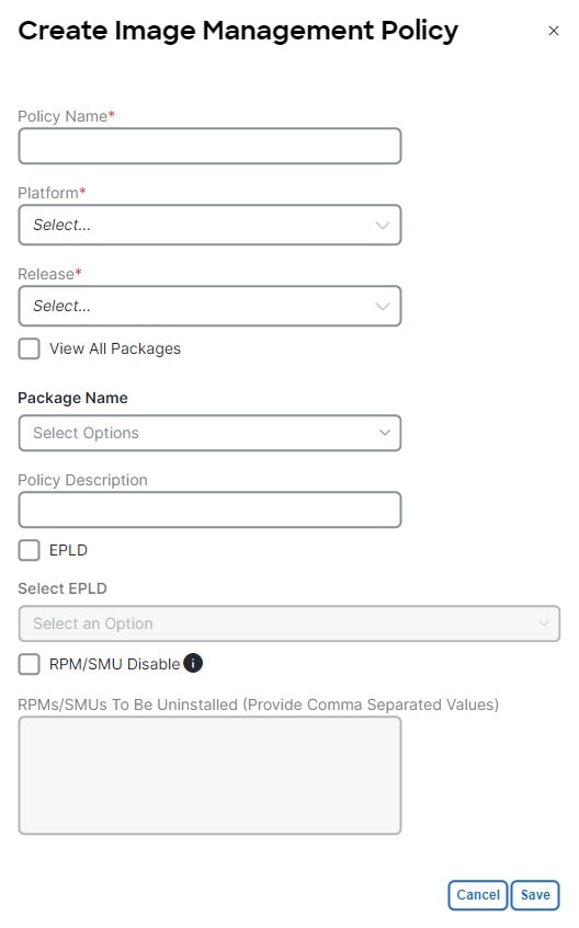
Depending on the switch type, not all fields in the Create Image Management Policy dialog box are available to all the devices.
-
Click Save.
Attach or detach update groups to the switches
This section describes how to attach or detach switches to or from an update group. Grouping allows you to track upgrades for a set of switches. You can create several groups and select a switch regardless of the group, role, or type of switch.
We recommend that you create update groups based on the roles of the switches. For example, if a fabric has multiple switches with different roles, such as Leaf, Spine, Border, and more, creating groups based on different roles is recommended. This clearly separates roles and responsibilities during switch image management operations. Switches with different roles perform critical functionality and respond differently based on the control plane, data plane, and system-level convergence. For example, a user with the admin role can create multiple groups as follows:
-
Group-Leaf-Even for Leaf switches that have even numbers or VPC role of primary
-
Group-Leaf-Odd for Leaf switches that have odd numbers or VPC role of secondary
Typically, Spine and Border devices are limited to fabric, while the role of the Leaf is the most common one. Therefore, users with the admin role can upgrade individual Spines followed by Individual Borders, or create different groups for Spines and Borders. Users with the admin role can still leverage groups to divide the Leaf role switches and perform bulk actions.
-
Navigate to the Fabric Software page for NX-OS and IOS-XE fabrics.
-
In the Fabric Software page, choose Devices.
-
In the Devices page, place a checkmark in the checkbox for the devices you want to group.
-
From the Actions drop-down list, select Modify groups.
-
In the Modify groups dialog box, click the radio button to either Attach Group or Detach Group.
-
Select Attach Group and choose Create Group to create a new group or select an existing group from the Group drop-down list.
-
To create a group, enter a group name in the Modify groups dialog box.
-
Click Save.
-
-
Select Detach Group and click Detach to detach the devices from a group. This deletes the Update group, if it is not assigned to any switches.
-
Attach a policy to the switches
This section describes how to attach a policy to the switches in disruptive mode.
-
Navigate to the Fabric Software page for NX-OS and IOS-XE fabrics.
-
In the Fabric Software page, choose Devices.
-
In the Devices page, select the devices you want to attach a policy.
-
From the Actions drop-down list, select Modify policy.
-
In the Modify policy dialog box, click the Attach Policy radio button and choose the required policy from the Policy drop-down list.
-
Select or deselect the Stage & Validate checkbox, if needed.
This option deploys the image on to the switch and validates for compatibility with the existing software version on the switch. The checkbox is selected by default. This runs the compatibility check with non-disruptive mode by default. If this check fails, then the compatibility check is run in disruptive mode.
You can uncheck this field while attaching the policy and perform a manual stage and validate, if required. For more information, see Copy the image to the switches and Validate the switches (optional).
-
Click Attach.
The table in the Devices tab displays the status of the stage and validate operations.
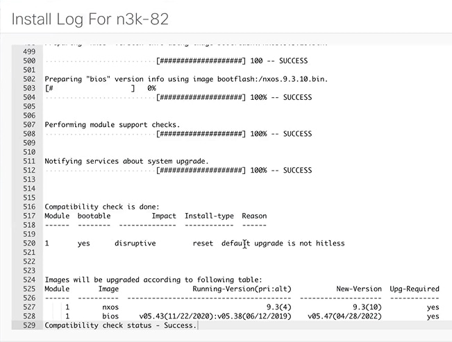
-
Click the link in the View Details column to view the install log for details about these operations. You can use the log to learn about errors, if any.
The History tab also provides logs for all the configuration changes and details about the errors.
On successful completion, the Image Staged and Validated columns will display a green icon for the respective devices.
Copy the image to the switches
The section describes how to copy the image to the switches.
-
Navigate to the Fabric Software page for NX-OS and IOS-XE fabrics.
-
In the Fabric Software page, choose Devices.
-
In the Devices page, place a checkmark in the checkbox for the device you want.
-
From the Actions drop-down list, select Stage image.
-
In the Stage image page, ensure there is enough space. The Primary Supervisor (Available Space in Bytes) displays in red if there is not enough space.
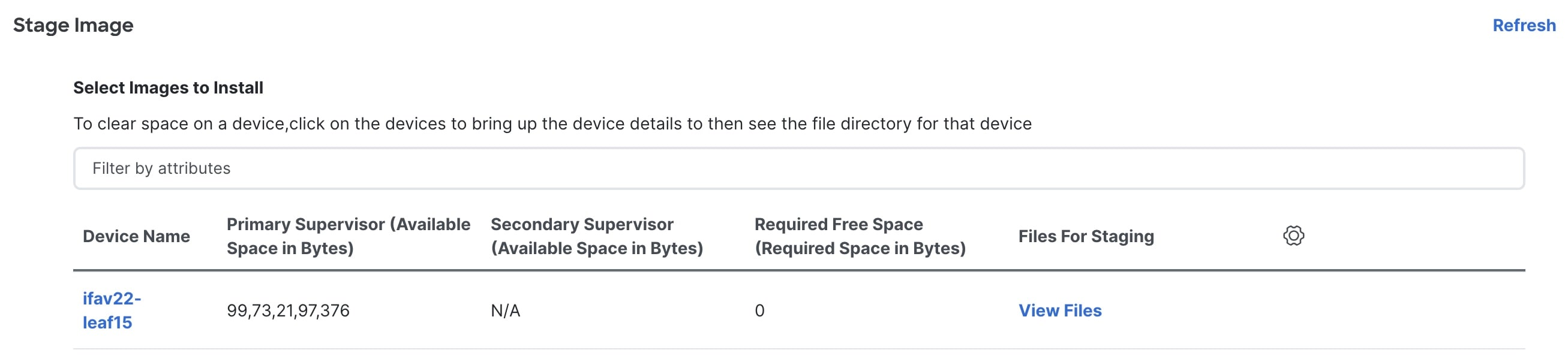
To make more space:
-
In the Stage image page, click on the device name.
-
In the Switch Overview page, ensure you are on the Hardware Bootflash tab. You will need to delete files to create space so you can stage the image.
-
Place a checkmark on the file names that you want to delete.
-
Click Actions and Delete files.
-
In the Warning Are you sure you want to delete? dialog box, click Confirm to delete the files.
-
Go back to the Stage image page and ensure the Required Free Space column displays 0.
-
In the Files for staging column, click View Files to view details such as File Name and Size of the image files to be staged.
-
-
Click Stage.
Validate the switches (optional)
This section describes how to validate the switches to find out which switches can be upgraded by doing a compatibility check. This checks if the image is complete, if the image is valid for the individual hardware, and if the upgrade can be non-disruptive. The log files provide detailed information for each switch.
-
Navigate to the Fabric Software page for NX-OS and IOS-XE fabrics.
-
In the Fabric Software page, choose Devices.
-
In the Devices page, place a checkmark in the checkbox for the device you want to validate.
-
From the Actions drop-down list, select Validate.
-
In the Validate dialog box, select this checkbox to know if non-disruptive update is allowed.
-
Click Validate.
-
In the Fabric Software page, under the View Details column, click Validate to check on the log file for that switch.

-
In the Fabric Software page, under the Validated column, you can see the validation progress until it completes.
-
If the validation completed successfully, it shows green.
-
If the validation fails, it shows red. Check the log file under the View Details column. You will need to fix the errors before proceeding.
-
Create and run the pre-ISSU report on the switches (optional)
This section describes how to create and run the pre-ISSU report on the switches (optional).
-
Navigate to the Fabric Software page for NX-OS and IOS-XE fabrics.
-
In the Fabric Software page, choose Devices.
-
In the Devices page, place a checkmark in the checkbox for the devices you want to run a report.
-
From the Actions drop-down list, select Run reports.
-
In the Create Report dialog box, choose Pre ISSU radio button.
-
Click Select a Template.
-
In the Select Report Template dialog box, choose either custom_swift_issu or issu_vpc_check template and click Select.
-
In the Report Name field, enter a name for the report.
Ensure that you provide the same name for the pre and the post-ISSU reports. This enables the system to associate the two reports.
-
Use the default values that are available in the fields and click Generate.
-
-
To view the reports:
-
Navigate to Analyze > Reports.
-
In the Reports page, click the link displayed under the Name column of the report that you want to view.
In the Report dialog box, you can see a summary and details about the errors, warnings, info and success messages. It also displays a snapshot of the configuration before and after the upgrade.
-
Click the link in the Results column.
The HTML version of the report is displayed.
These reports cannot be edited or deleted.
-
Generate pre-upgrade or post-upgrade snapshots of the switch configuration (optional)
This topic describes how to generate snapshots of the configuration of a switch. It is a best practice to generate snapshots of the switch configuration before entering and after exiting the maintenance mode for performing an upgrade. You can use this to compare the configuration of the switch before it was moved into maintenance mode and after bringing back to normal mode.
-
Navigate to the Fabric Software page for NX-OS and IOS-XE fabrics.
-
In the Fabric Software page, choose Devices.
-
In the Devices page, place a checkmark in the checkbox for the required device.
-
From the Actions drop-down list, choose Generate snapshot.
-
In the Generate snapshot dialog box, click either Pre-Upgrade-Snapshot or Post-Upgrade-Snapshot.
-
Click Save.
Based on the selection in the previous step, the system generates a pre-upgrade or post-upgrade snapshot for the switch. These snapshots are also saved in the switch bootflash.
-
Click the link in the View Details column for the respective switch to view the generated snapshot. These snapshots are only available after the pre-upgrade and post-upgrade snapshots are run.
The History tab also provides logs for all the configuration changes and details about the errors.
Change mode for a switch
This section describes how to change mode for a switch.
-
Navigate to the Fabric Software page for NX-OS and IOS-XE fabrics.
-
In the Fabric Software page, choose Devices.
-
In the Devices page, place a checkmark in the checkbox for the device you want.
-
From the Actions drop-down list, select Change Mode.
-
In the Change Mode dialog box, choose either Normal or Maintenance mode.
-
Click Deploy Now or Deploy Later.
Software update analysis
The Software update analysis page provides a comprehensive overview of your network’s readiness for a software upgrade.
Pre-update analysis report
Follow these steps to view the pre-update analysis report.
-
Navigate to Fabric Software page.
Go to Manage > Fabric Software
-
In the Fabric Software page, click the ACI tab.
-
Click View Results.
The Software update analysis page opens.
-
In the Software update analysis page, go to Analysis results > Pre-update analysis > View report .
The Pre-update report page opens.
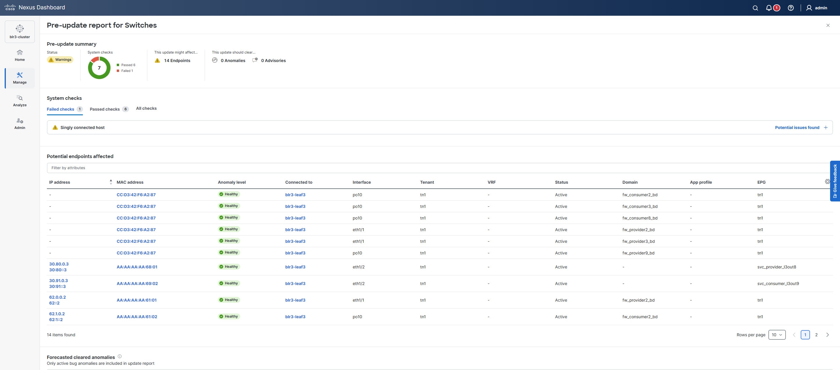
The Pre-update report page provides a summary of the current status of your nodes, highlights potential issues detected, identifies endpoints that may be affected, and lists alerts expected to be resolved after the update. It also outlines any release defects that could arise post-update and includes forecasts for anomalies and advisories.
If you address any issues listed in the System checks section, click Rerun report to update the results. Click Potential issues found under System checks to view a table that shows the results of each system check.
-
If a check has passed, the table displays the check name and its status.
-
If a check has failed, the table displays the devices that failed and provide information on how to fix the issue.
You can either run an upgrade snapshot or a pre-update analysis, not both at the same time.
Pre-validation criteria for NXOS fabric
| Pre-validation criteria | Description |
|---|---|
|
Modules health and backup power |
Executes |
|
All filesystem free space |
Executes |
|
NVRAM log messages |
Executes the |
|
General log messages |
Executes the |
|
Devices connectivity check |
Confirms that the SIM status for the device is reported as "Good". Device Availability: Verifies the device is not busy with other operations. Command Execution: Attempts to execute a basic command ( |
|
Module status |
Executes the
Modules showing error or power-denied states require further investigation. |
|
Dual supervisor redundancy |
Executes the
|
|
Diag module |
Executes the |
|
vPC state |
Executes the
Specifically verify that the vPC peer-keepalive link is operational, vPC peer-link is up, all configured vPCs are in the up state, and there are no consistency failures reported. |
|
vPC sticky bit |
Executes the |
|
vPC secondary role |
Executes the |
|
OSPF state |
Executes
Also checks that every neighbor relationship has remained stable for at least 12 hours (as specified by the configured parameter). |
|
BGP state |
Executes the |
|
HSRP mgo state |
Executes the
|
|
Free-space on bootflash |
Executes |
|
Management console |
Executes the Verifies that the following three critical control signals are active:
|
|
Singly connected host |
Retrieves all endpoints connected to the nodes in your upgrade group. Identifies "singly connected" endpoints by checking for:
|
Pre-validation criteria for ACI fabric
| Pre-validation criteria | Description |
|---|---|
|
Found inactive devices |
Checks if all devices are active. |
|
Select a compatible target version |
Checks if the target firmware version is compatible with the current running version. |
|
Remote leaf compatibility |
Checks if remote leaf feature is supported in the target firmware version and if the fabric is using remote leaf feature. |
|
Multi-tier compatibility |
Checks if multi-tier topology is supported in the target firmware version and if the fabric has Tier-2 leaf nodes. This check is mainly for downgrade scenario. |
|
The fabric has 4 active critical configuration faults |
Checks the presence of critical configuration faults or specific faults that may impact the firmware update. |
|
Pod(s) have fewer than two route reflectors for infra MP- BGP |
Checks if each pod has at least two spine nodes configured as route reflectors for infra MP-BGP. |
|
Nodes are not in vPC |
Checks if leaf nodes are configured with vPC to ensure the redundancy/high availability during the firmware update. |
|
Nodes do not have out-of-band management IP |
Checks the presence of nodes without out-of-band (OOB) management IP configuration to ensure that you always have access to all nodes. |
|
NTP is not configured |
Checks if Network Time Protocol (NTP) is configured for Cisco APICs. |
|
Switch upgrade maintenance group check |
Checks if APICs have maintenance and firmware groups. |
|
Failed to validate rule |
Checks if the target firmware version is compatible with current running CIMC versions. |
|
Cisco APICs in cluster have different infra VLAN IDs |
Checks if APICs in the cluster have same infra VLAN IDs. |
|
Cisco APIC cluster status is not fully-fit for all APIC nodes |
Checks if the APIC cluster status is fully-fit for all APIC nodes. |
|
Fabric recovery is in progress |
Checks if there is any fabric recovery in progress. |
|
The configured SNMPv3 user authorization and/or privacy types are not supported in the target Cisco APIC firmware version |
Checks if configured SNMPv3 user authorization and/or privacy types are supported in the target APIC firmware version. |
|
Endpoint network redundancy |
Checks if nodes have non-redundant endpoints to avoid traffic loss during the reboot of nodes. |
|
APIC cluster status |
Checks if the APIC cluster status is fully-fit for all APIC nodes. If the status is data-layer-partially-diverged or any value other than fully-fit, firmware update for APICs and switches should not be performed. |
|
APIC disk space |
Checks for any faults indicating that an APIC is running low on disk space, which could cause the APIC upgrade to fail. APICs can raise three different faults depending on the remaining disk space. If any of these faults are present, they must be resolved before performing the upgrade. |
|
Switch bootflash usage |
Checks if there is enough bootflash storage to successfully upgrade a switch node. |
|
APIC SSD health |
Checks if there are any faults indicating issues with the APIC SSD health status. |
|
Switch SSD health |
Checks if there are any faults indicating issues with the Switch SSD health status. |
|
Daily configuration backup |
Checks whether a valid configuration backup was created within the last 24 hours. |
|
NTP configuration |
Checks if NTP is configured for APICs. |
|
NTP status |
Checks if NTP is synchronized on APICs and switches within the fabric. |
|
OOB management IP |
Identifies nodes lacking OOB management IP configuration to ensure continuous access to all nodes. During upgrades or downgrades, some nodes may become unreachable through ACI infrastructure. It is also recommended to prepare console access for each node as a precaution. |
|
Ongoing fabric recovery |
Checks whether any fabric recovery processes are currently in progress. |
|
Active apps |
Identifies any active apps in the APIC that need to be disabled. |
|
Configuration zones |
Checks if there are any configuration zones that need to be disabled or removed prior to the upgrade. |
|
Switch high availability (vPC leafs) |
Verifies that leaf nodes are configured with vPC to ensure redundancy and high availability during the firmware update. If redundancy is provided by other methods (such as ECMP), or if single-homed servers are used intentionally, this check can be disregarded. |
|
Switch high availability (spine route reflectors) |
Verifies that each pod has at least two spine nodes configured as route reflectors for infra MP-BGP. If all route reflector spines become unavailable simultaneously, the fabric may lose reachability to external routes from L3Outs. |
|
Upgrade group (spine HA) |
If any maintenance groups are present, this validation checks for the following:
|
|
Upgrade group (vPC HA) |
Checks that both leaf nodes of the same vPC pair are not in the same upgrade group. |
|
Upgrade group (APIC leaf HA) |
Checks that both leaf nodes connected to the same APIC do not belong to the same upgrade group. |
|
Critical configuration faults |
Checks the presence of critical config faults or specific faults that may impact the firmware update. |
|
Controller port configuration conflict |
Identifies any faults indicating that a configuration is being rejected because it is deployed on a port connected to an APIC. |
|
L3 interface deployment conflict |
Identifies any faults indicating that L3 configuration is being rejected on a port already operating in L2 mode. |
|
L2 interface deployment conflict |
Identifies any faults indicating that L2 configuration is being rejected on a port already operating in L3 mode. |
|
Overlapping BD subnets |
Identifies any faults indicating that BD subnets are overlapping but not identical within the same VRF. Only one of these configurations is effective at a time, so after an upgrade, a different BD subnet may become active. |
|
Duplicated BD subnets |
Identifies any faults indicating that external Bridge Domains within the same VRF have overlapping prefixes. |
|
External EPG prefix overlap |
Identifies any faults indicating that external EPGs within the same VRF have overlapping prefixes. |
|
HW programming failure (L3Out prefixes, contracts) |
Identifies any faults indicating that L3Out prefix-to-pcTag mapping entries or contracts failed to be programmed. |
|
Scalability (faults related to capacity dashboard) |
Identifies any statistics faults, Threshold Crossing Alerts (TCA) related to By default, not all statistics in the capacity dashboard have thresholds configured to raise faults. Thresholds can be reviewed and configured under: Fabric > Fabric Policies > Policies > Monitoring > default > Stats Collection Policies > Monitoring Object > Equipment Capacity Entity (eqptcapacityEntity) > Stats Type. |
|
Overlapping VLAN pools |
Detects VLAN pools with overlapping VLAN IDs assigned to the same EPG. This configuration may cause traffic issues during or after an upgrade, unless it is intentional and you are familiar with how VNIDs are assigned and function in ACI. |
|
ISIS redistribution metric for multi-pod/multi-site |
Checks ISIS redistribution metrics for multi-pod and multi-site. |
|
L3Out MTU size |
Verifies the MTU size configured on all L3Outs in the fabric. If the MTU size on the ACI L3Out and the connected devices do not match, route exchange may fail after an upgrade—even if it worked previously. |
|
Different Infra VLAN via LLDP |
Identifies any faults related to interfaces connected back-to-back between two different ACI fabrics. LLDP should be disabled on these interfaces before upgrades, as switches may process LLDP packets from the other fabric using a different infra VLAN after reboot. This can cause the switch to attempt discovery through the incorrect infra VLAN, making it undiscoverable in the intended fabric. |
|
Offline VMM domain |
Checks if any VMM domains have controllers which are offline. |
|
VMM domain LLDP/CDP adjacency |
Identifies any faults indicating that the APIC cannot retrieve LLDP/CDP information from the vSwitch through vCenter for VMM DVS integration. This information is required to detect which ACI switch interfaces should have VLANs deployed dynamically. |
|
CIMC compatibility |
Checks if the target firmware version is compatible with current running CIMC versions. |
|
Version compatibility |
Checks if the target firmware version is compatible with the currently running version. |
|
Remote leaf compatibility |
Verifies that the remote leaf feature is supported in the target firmware version if the fabric is using this feature. This check is especially important for downgrade scenarios. |
|
Switch upgrade maintenance group check |
Verifies that maintenance and firmware groups exist on the APICs before upgrading from pre-4.0 to 4.0 or later releases. |
|
Infra VLAN ID check |
Verifies that all APICs in the cluster have the same infra VLAN ID configured. |
|
SNMPv3 auth compatibility |
Checks whether the configured SNMPv3 user authentication and privacy types are supported in the target APIC firmware version. |
Upgrade or downgrade switches
This section describes how to upgrade or downgrade a switch or a group of switches or uninstall RPMs.
-
Navigate to the Fabric Software page for NX-OS and IOS-XE fabrics.
-
In the Fabric Software page, choose Devices.
-
Do one of the following:
-
Place a checkmark in the checkbox for the device you want to upgrade.
-
To upgrade a group of switches, filter on the Update Groups, select all, and place a checkmark in the checkbox for all the devices you want.
-
-
From the Actions drop-down list, select Upgrade.
You can choose to either upgrade NOS, EPLD, or RPM separately or all at once. EPLD Golden must be upgraded separately.
-
Click on the Upgrade radio button.
-
In the Select Upgrades field, place a checkmark on the upgrades you want.
For Cisco Catalyst switches, you can only upgrade the NOS. EPLD and SMU upgrades are currently not supported.
-
From the Upgrade Options drop-down list, select Disruptive or Non-Disruptive.
-
If you selected Disruptive in the previous step, you can choose to enable BIOS Force.
Selecting this option requires a reload.
If you chose Non-Disruptive in the previous step, then BIOS Force is disabled by default.
-
You can view the Validation Status and filter, if needed.
-
You can also view the Pre-ISSU report status by clicking on the hyperlink.
-
Click Upgrade.
-
Run the post-ISSU report on the switches (optional)
This section describes how to run the post-ISSU report on switches.
You must wait until the switch is fully operational before running the Post-ISSU.
-
Navigate to the Fabric Software page for NX-OS and IOS-XE fabrics.
-
In the Fabric Software page, choose Devices.
-
In the Devices page, place a checkmark in the checkbox for the devices you want to run the post-ISSU.
-
From the Actions drop-down list, select Run reports.
-
In the Create Report dialog box, choose Post ISSU radio button.
-
Click Select a Template.
-
In the Select Report Template dialog box, choose either the custom_swift_issu or issu_vpc_check template and click Select.
-
From the Report Name drop-down list, select the name of the pre-ISSU report that you have generated and click Generate.
-
Use the default values that are available in the fields and click Generate. The system generates the report when ready. Ensure the status displays successful.
-
You can click on the link under the Results column to view the HTML version of the report.
The post-ISSU report displays a summary of the results of the checks performed before and after the upgrade, consecutively. Analyze the report for any errors and take corrective actions, as required.
-
-
To view the reports:
-
Navigate to Analyze > Reports.
-
In the Reports page, click the link displayed under the Name column of the report that you want to view.
In the Report dialog box, you can see a summary and details about the errors, warnings, info and success messages. A snapshot of the configuration before and after the upgrade is also displayed.
These reports cannot be edited or deleted.
-
Generate post-upgrade snapshot of the switch configuration (optional)
This topic describes how to generate snapshots of the configuration of a switch. It is a best practice to generate snapshots of the switch configuration before entering and exiting the maintenance mode for performing an upgrade. You can use this to compare the configuration of the switch before it was moved into maintenance mode and after bringing back to normal mode.
-
Navigate to the Fabric Software page for NX-OS and IOS-XE fabrics.
-
In the Fabric Software page, choose Devices.
-
In the Devices page, place a checkmark in the checkbox for the required device.
-
From the Actions drop-down list, choose Generate snapshot.
-
In the Generate snapshot dialog box, click Post-Upgrade-Snapshot.
-
Click Save.
The system generates a post upgrade snapshot for the switch.
-
Click the link in the View Details column for the respective switch to view the snapshots and the pre and post snapshot comparison summary generated for the switch.
The History tab also provides logs for all the configuration changes and details about the errors.
Post-update analysis report
Follow these steps to view the post-update analysis report.
-
Navigate to Fabric Software page.
Go to Manage > Fabric Software
-
In the Fabric Software page, click the ACI tab.
-
Click View Results.
The Software update analysis page opens.
-
In the Software update analysis page, go to Analysis results > Post-update analysis > View report .
The Post-update report page opens.
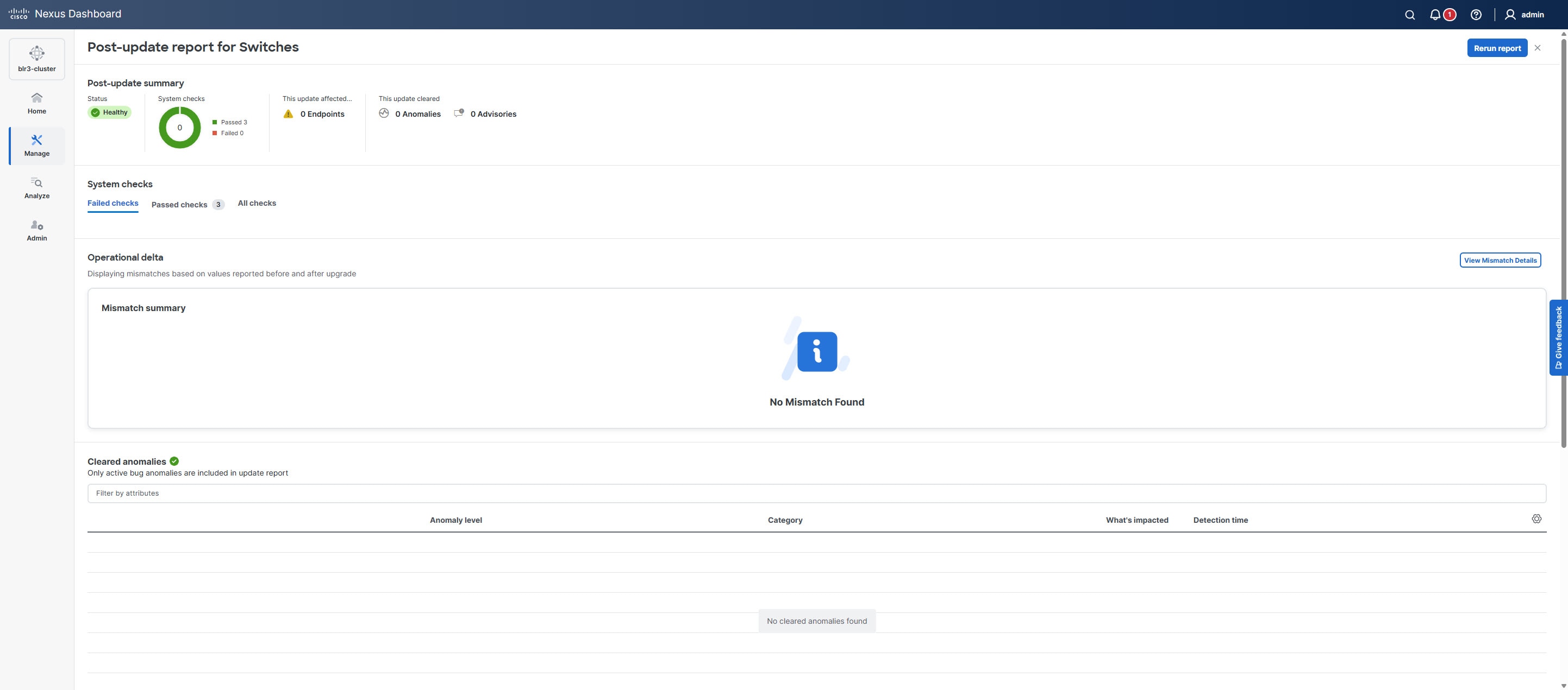
This Post-update report page provides a summary that indicates the overall status of the upgrade. You can also find these details.
-
System checks — Displays detailed results of system validation checks such as Failed checks, Passed checks, and All checks.
-
Operational delta — Click View Mismatch Details to view the changes in operational resources between the pre-upgrade and post-upgrade analyses. This helps in understanding what operational changes are introduced during the upgrade.
-
Cleared anomalies — Lists only the active bug anomalies that were present before the upgrade but have been resolved as a result of the upgrade.
-
Cleared advisories — Displays only the software end-of-life and PSIRT advisories that are no longer applicable post-upgrade.
-
Rerun report — Provides an option to rerun the post-upgrade analysis to verify the current system status or after making further changes.
Uninstall packages from a switch
This section describes how to uninstall packages from a switch. You first need to take note of the patch names, detach the packages, and then uninstall them.
-
Navigate to Manage > Inventory.
-
Place a checkmark in the checkbox for the device you want to uninstall packages from.
-
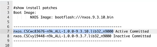
From the Actions drop-down list, select More > Show Commands.
-
In the Switch show commands page, enter the following:
-
In the Commands field, choose show.
-
Under the Variables section, in the show field, enter install patches.
In the right pane it lists the package names. Take note of the package names you want to uninstall by copying the file name. For example:
-
Exit the page.
-
-
Navigate to the Fabric Software page for NX-OS and IOS-XE fabrics.
-
In the Fabric Software page, choose Image Policies.
-
From the Actions drop-down list, select Create.
-
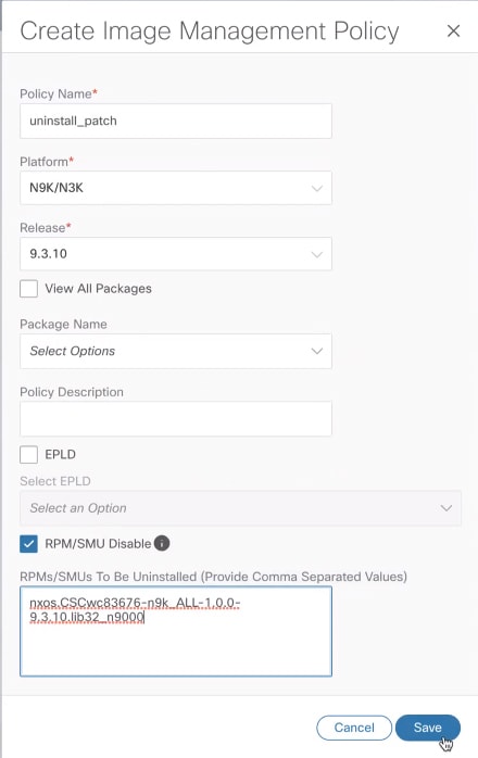
In the Created Image Management Policy dialog box, enter the following:
-
In the Policy Name field, enter a policy name. For example, uninstall_patch.
-
From the Platform drop-down list, choose the correct platform.
-
Do not check the View All Packages checkbox.
-
In the Package Name field, leave it blank.
-
In the Policy description field, leave it blank.
-
Do not check the ELPD checkbox.
-
In the Select ELPD field, leave it blank.
-
Place a checkmark in the RPM/SMU Disable in the checkbox.
-
In the RPMs/SMUs To Be Uninstalled field, enter the packages.
Provide a comma to separate the values.
-
Click Save.
-
-
In the Fabric Software page, choose Devices.
-
In the Devices page, place a checkmark in the checkbox for the devices you want to modify the policy.
-
From the Actions drop-down list, select Modify policy.
-
In the Modify policy dialog box, enter the following:
-
Click on the Attach Policy radio button.
-
In the Policy field, select the Policy and click Attach. For example:

-
-
The switch then recalculates based on the above selection. Click the Status column for information about the switch. For example:
-
In the Status column, it shows the packages that will be removed.
-
To remove the packages, in the Devices page, make sure the checkmark is placed in the checkbox for the devices you want to remove the packages from.
-
From the Actions drop-down list, select Upgrade.
-
In the Upgrade/Uninstall page, enter the following:
-
Click on the Uninstall radio button and click Uninstall.
-
In the Devices page, you can check the uninstall progress of the device if you click on the Upgrade under the View Details column.
-
Once the packages have been removed, the status will show In-Sync in green and Upgrade will show a green button.
-
In the Devices page, you can also verify if the packages were uninstalled successfully by viewing the log file. Click on Upgrade for that device under the View Details column.
-
Understand Fabric Software for ACI fabrics
This section provides detailed information for the Fabric Software feature in Nexus Dashboard for ACI fabrics.
Navigate to the Fabric Software page for ACI fabrics
To navigate to the Fabric Software page:
-
Click Manage > Fabric Software.
-
Click the ACI tab.
-
Cisco’s recommended versions: The software versions that Cisco recommends. These are the latest versions available for upgrade or for running an analysis.
-
Current version: This is the software version that the fabric is currently running.
-
Recommended: Displays the recommended software version to upgrade to. This version is determined based on the current version the fabric is running on.
For example, if the fabric is currently on version 6.0(3d), then the Recommended version indicates 6.0(3d). However, if the Current version is newer than the recommended versions, then this field will be blank.
-
NOTE:
-
Delta analysis is no longer a part of the post-upgrade assist workflow. In Delta analysis, you can only run an analysis per fabric unlike Upgrade assist, where you can choose a subset of devices to analyse.
-
When you initially run an analysis, you can Rerun the report from the Pre-update analysis drawer to collect fresh data. Once your devices are upgraded, you can run a post-upgrade analysis. However, this disables the Rerun the report button in the pre-update analysis drawer.
Understand the information provided in the Fabric Software page for ACI fabrics
-
Connect to Intersight if you are not connected already.
Hover over the link icon in the Sofware Versions area to see if you are connected to Intersight. Intersight connectivity is required for Nexus Dashboard to automatically check for recommended software versions for the ACI fabrics. See Working with Intersight for more information.
-
Review the information in the Software Versions area.
The Software Versions area provides information on recommended software releases for your ACI fabrics and links to the Release Notes for those software releases.
Copyright
THE SPECIFICATIONS AND INFORMATION REGARDING THE PRODUCTS IN THIS MANUAL ARE SUBJECT TO CHANGE WITHOUT NOTICE. ALL STATEMENTS, INFORMATION, AND RECOMMENDATIONS IN THIS MANUAL ARE BELIEVED TO BE ACCURATE BUT ARE PRESENTED WITHOUT WARRANTY OF ANY KIND, EXPRESS OR IMPLIED. USERS MUST TAKE FULL RESPONSIBILITY FOR THEIR APPLICATION OF ANY PRODUCTS.
THE SOFTWARE LICENSE AND LIMITED WARRANTY FOR THE ACCOMPANYING PRODUCT ARE SET FORTH IN THE INFORMATION PACKET THAT SHIPPED WITH THE PRODUCT AND ARE INCORPORATED HEREIN BY THIS REFERENCE. IF YOU ARE UNABLE TO LOCATE THE SOFTWARE LICENSE OR LIMITED WARRANTY, CONTACT YOUR CISCO REPRESENTATIVE FOR A COPY.
The Cisco implementation of TCP header compression is an adaptation of a program developed by the University of California, Berkeley (UCB) as part of UCB’s public domain version of the UNIX operating system. All rights reserved. Copyright © 1981, Regents of the University of California.
NOTWITHSTANDING ANY OTHER WARRANTY HEREIN, ALL DOCUMENT FILES AND SOFTWARE OF THESE SUPPLIERS ARE PROVIDED “AS IS" WITH ALL FAULTS. CISCO AND THE ABOVE-NAMED SUPPLIERS DISCLAIM ALL WARRANTIES, EXPRESSED OR IMPLIED, INCLUDING, WITHOUT LIMITATION, THOSE OF MERCHANTABILITY, FITNESS FOR A PARTICULAR PURPOSE AND NONINFRINGEMENT OR ARISING FROM A COURSE OF DEALING, USAGE, OR TRADE PRACTICE.
IN NO EVENT SHALL CISCO OR ITS SUPPLIERS BE LIABLE FOR ANY INDIRECT, SPECIAL, CONSEQUENTIAL, OR INCIDENTAL DAMAGES, INCLUDING, WITHOUT LIMITATION, LOST PROFITS OR LOSS OR DAMAGE TO DATA ARISING OUT OF THE USE OR INABILITY TO USE THIS MANUAL, EVEN IF CISCO OR ITS SUPPLIERS HAVE BEEN ADVISED OF THE POSSIBILITY OF SUCH DAMAGES.
Any Internet Protocol (IP) addresses and phone numbers used in this document are not intended to be actual addresses and phone numbers. Any examples, command display output, network topology diagrams, and other figures included in the document are shown for illustrative purposes only. Any use of actual IP addresses or phone numbers in illustrative content is unintentional and coincidental.
The documentation set for this product strives to use bias-free language. For the purposes of this documentation set, bias-free is defined as language that does not imply discrimination based on age, disability, gender, racial identity, ethnic identity, sexual orientation, socioeconomic status, and intersectionality. Exceptions may be present in the documentation due to language that is hardcoded in the user interfaces of the product software, language used based on RFP documentation, or language that is used by a referenced third-party product.
Cisco and the Cisco logo are trademarks or registered trademarks of Cisco and/or its affiliates in the U.S. and other countries. To view a list of Cisco trademarks, go to this URL: https://www.cisco.com/go/trademarks. Third-party trademarks mentioned are the property of their respective owners. The use of the word partner does not imply a partnership relationship between Cisco and any other company. (1110R)
© 2017-2025 Cisco Systems, Inc. All rights reserved.
Americas Headquarters
Cisco Systems, Inc.
170 West Tasman Drive
San Jose, CA 95134-1706
USA
https://www.cisco.com
Tel: 408 526-4000
800 553-NETS (6387)
Fax: 408 527-0883