Preinstallation
 Note |
Before you install, operate, or service the system, see the Regulatory Compliance and Safety Information for the Cisco MDS 9000 Family for important safety information. |
 Warning |
This warning symbol means danger. You are in a situation that could cause bodily injury. Before you work on any equipment, be aware of the hazards involved with electrical circuitry and be familiar with standard practices for preventing accidents. Use the statement number provided at the end of each warning to locate its translation in the translated safety warnings that accompanied this device. Statement 1071 SAVE THESE INSTRUCTIONS |
Warning |
This unit is intended for installation in restricted access areas. A restricted access area can be accessed only through the use of a special tool, lock and key, or other means of security. Statement 1017 |
Warning |
Only trained and qualified personnel should be allowed to install, replace, or service this equipment. Statement 1030 |
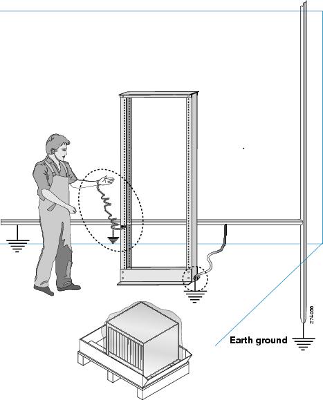
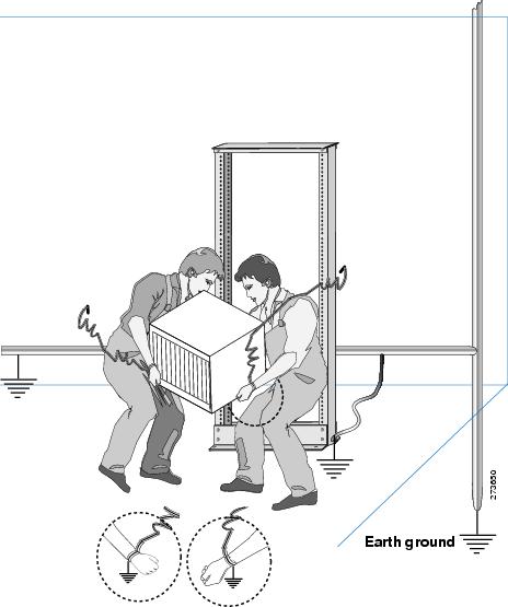
Installing the ESD Grounding Strap
This section illustrates how to prepare yourself before removing the chassis from the sealed antistatic bag.
The figures show how to cuff the ESD strap around the wrist and the ground cord that connects the cuff to the ground. ESD wrist straps are the primary means of controlling static charge on personnel.
Note |
These images are for only representation purposes. The chassis' actual appearance and size may vary. |
Unpacking and Inspecting the Switch
To inspect the shipment, follow these steps:
Before you begin
 Caution |
When handling switch components, wear an ESD strap and handle modules by the carrier edges only. An ESD socket is provided on the chassis. For the ESD socket to be effective, the chassis must be grounded through the power cable, the chassis ground, or the metal-to-metal contact with a grounded rack. |
 Tip |
Keep the shipping container in case the chassis requires shipping in the future. |
Note |
If you purchased Cisco support through a Cisco reseller, contact the reseller directly. If you purchased support directly from Cisco, contact Cisco Technical Support at this URL: http://www.cisco.com/c/en/us/support/web/tsd-cisco-worldwide-contacts.html. |
Procedure
|
Step 1 |
Compare the shipment to the equipment list provided by your customer service representative and verify that you have received all items, including the following:
|
|
Step 2 |
Check for damage and report any discrepancies or damage to your customer service representative. Have the following information ready:
|
|
Step 3 |
Check if all the power supplies and the fan trays have the expected direction of airflow. Port-side-intake airflow modules have a burgundy coloring, and port-side exhaust airflow modules have blue coloring. The airflow direction must be the same for all modules. |
Installation Options
The Cisco MDS 9396V Switch can be installed using the following methods:
-
In an open EIA rack.
-
In a perforated or solid-walled EIA cabinet.
The rack-mount kit enables you to install the switch into racks of varying depths. You can use the rack-mount kit parts to position the switch with easy access to the port connections end of the chassis and the end of the chassis with the fan and power supply modules. For instructions on how to install the rack-mount kit, see the Installing the Switch.
Note |
The EIA Shelf Bracket Kit is optional and is not provided with the switch. To order the kit, contact your switch provider. |
Cisco MDS 9000 Family Telco and EIA Shelf Bracket
The optional EIA Shelf Bracket Kit (part number DS-SHELF=) can temporarily or permanently support the Cisco MDS 9396V switch during installation. Once the front rack-mount brackets are securely attached to the rack-mounting rails, the shelf bracket can be removed.
This kit supports a Cisco MDS 9396V Switch in a four-post EIA rack.
Note |
This optional kit is not provided with the switch; to order the kit, contact your switch supplier. |
This section describes the procedure for installing a Cisco MDS 9396V switch in a rack or cabinet using the optional EIA Shelf Bracket Kit.
Shelf Installation Guidelines
Caution |
If the rack is on wheels, ensure that the brakes are engaged, or the rack is otherwise stabilized. |
Caution |
If you are installing this kit in an EIA rack, attach the shelf to all four rack-mounting posts; the EIA posts may not be thick enough to prevent flexing of shelf brackets if only two posts are used. |
Before rack-mounting the chassis, ensure that the cabinet or rack meets the requirements listed in the General Requirements section.
Before Installing the Shelf Brackets
Before installing the shelf brackets, inspect the contents of your kit. The following table lists the contents of the shelf bracket kit.
| Quantity | Part Description |
|---|---|
| 2 | Slider brackets |
| 2 | Slider brackets |
| 1 | Crossbar |
| 2 | 10-32 x 3/8-in. Phillips pan-head screws |
| 16 | 12-24 x 3/4-in. Phillips screws |
| 16 | 10-24 x 3/4-in. Phillips screws |
Required Equipment
You need the following equipment for this installation:
-
Number 2 Phillips screwdriver
-
Tape measure and level (to ensure shelf brackets are level)
Installing the Shelf Bracket Kit into a Four-Post EIA Rack
The following figure shows the installation of the shelf bracket kit into a four-post EIA rack.
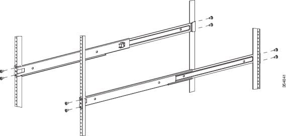
To install the shelf brackets in an EIA rack, follow these steps:
Procedure
|
Step 1 |
Position a shelf bracket inside the rack-mounting rails as shown in the above figure. Align the screw holes at the front of the shelf bracket with the holes in the front rack-mounting rail. Then attach the shelf bracket to the front rack-mounting rail using a minimum of four 12-24 or 10-24 screws.
|
||
|
Step 2 |
Repeat with the other shelf bracket. |
||
|
Step 3 |
Verify that the shelf brackets are at the same height (using the level or tape measure as desired). |
||
|
Step 4 |
Attach the crossbar to the shelf brackets as shown in the above figure, using the 10-32 screws. |
||
|
Step 5 |
Insert the slider rails into the shelf brackets as shown in the above figure. Attach them to the rear rack-mounting rails using a minimum of four 12-24 or 10-24 screws. |
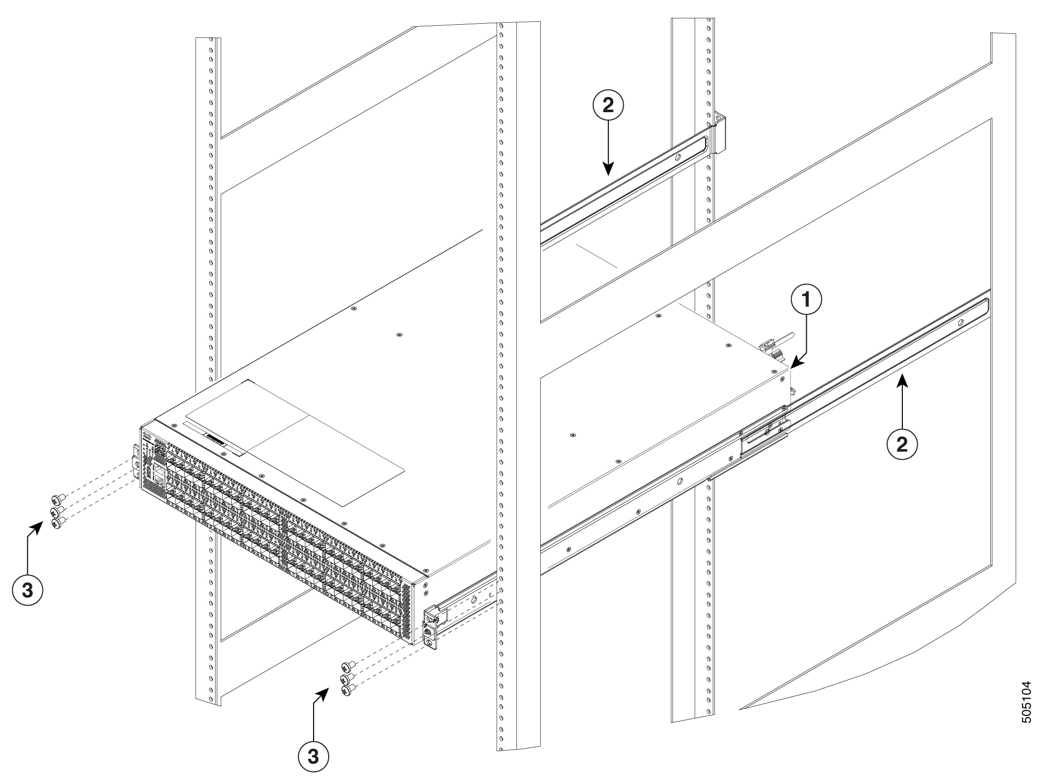
Installing the Switch on the Shelf Brackets
This section provides general instructions for installing the switch on top of the shelf brackets.
Warning |
This unit is intended for installation in restricted access areas. A restricted access area can be accessed only through the use of a special tool, lock and key, or other means of security. Statement 1017 |
Warning |
Only trained and qualified personnel should be allowed to install, replace, or service this equipment. Statement 1030 |
Note |
Before you install, operate, or service the system, refer to the Regulatory Compliance and Safety Information for the Cisco MDS 9000 Family for important safety information. |
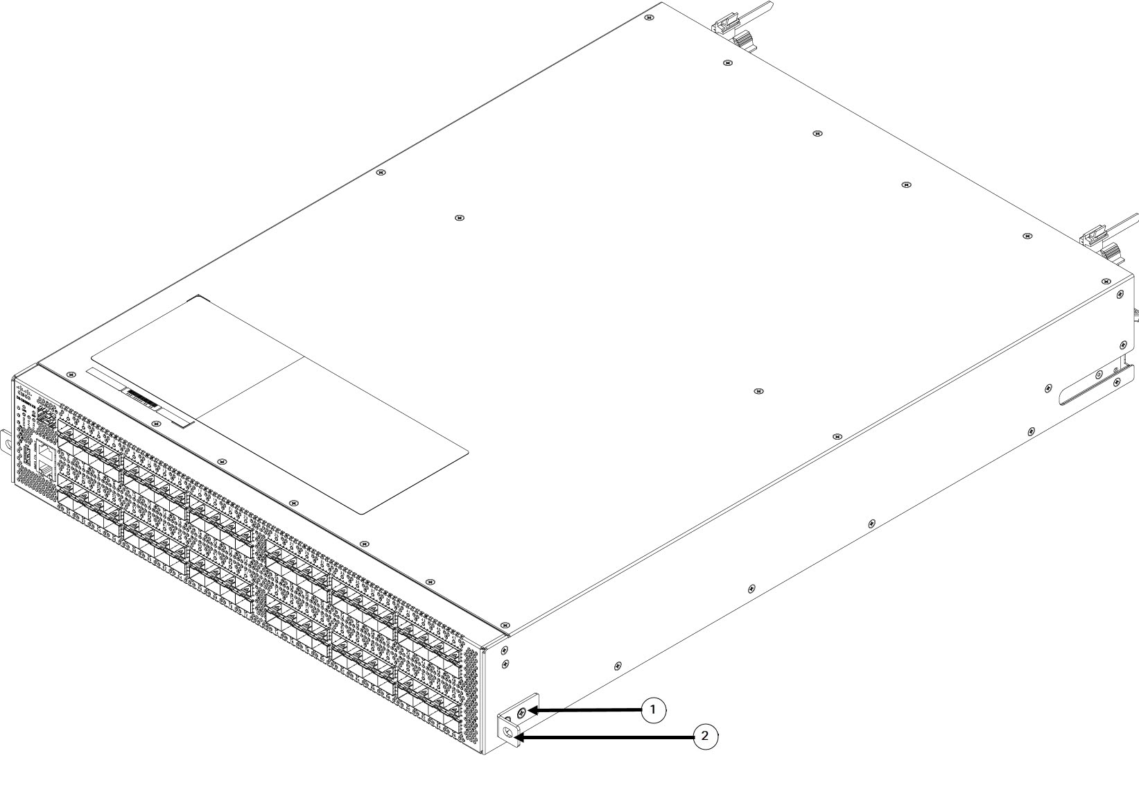
To install the switch on top of the shelf brackets, follow these steps:
Procedure
|
Step 1 |
Verify that the shelf brackets are level and securely attached to the rack-mounting rails, the crossbar is securely attached to the shelf brackets, and the rack is stabilized. |
||||
|
Step 2 |
Slide the switch onto the shelf brackets, ensuring that it is squarely positioned. |
||||
|
Step 3 |
Attach the switch to the rack-mounting rails.
|
Removing the Shelf Bracket Kit (Optional)
To remove the shelf bracket kit, follow these steps:
Before you begin
The shelf bracket kit can be removed after the Cisco MDS 9396V switch is installed in a four-post EIA rack, and both front rack-mount brackets and both C brackets are securely attached to the rack-mounting rails.
Procedure
|
Step 1 |
Remove the screws fastening the slider brackets to the rear rack-mounting rails, and then slide the slider brackets out of the shelf brackets. |
|
Step 2 |
Remove the screws fastening the crossbar to the shelf brackets, and then remove the crossbar. |
|
Step 3 |
Remove the screws fastening the shelf brackets to the front rack-mounting rails and remove the shelf brackets from the rack. |
Preinstallation Guidelines
Airflow Considerations
The switch comes with fan modules and power supply units that have either port-side intake or port-side exhaust airflow for cooling the switch. If you are orienting the switch with the FC ports facing a cold aisle, make sure that the switch has a port-side intake fan and power supply modules with red colorings. If you are orienting the switch with the fan and power supply modules facing a cold aisle, make sure that the switch has port-side exhaust fan and power supply units with blue colorings. All fan modules and power-supply modules must have the same direction of airflow.
Connection Guidelines for AC-Powered Systems
To connect to the Cisco MDS 9396V switch AC power supply units to the site power source, follow these guidelines:
-
For power redundancy, each power supply should be connected to a separate power feed (at a minimum, separate branch circuits).
-
Circuits should be sized according to local and national codes.
-
The AC power receptacles that are used to power the chassis must be the grounding type. The grounding conductors that connect to the receptacles should connect to protective earth ground in the service equipment.
Installation Guidelines
Follow these guidelines when installing the Cisco MDS 9396V Switch:
-
Plan your site configuration and prepare the site before installing the switch.
-
Each new switch requires a license; see the Cisco MDS 9000 Series Licensing Guide for instructions on installing a license.
-
Ensure there is adequate space around the switch to allow for servicing the switch and for adequate airflow (airflow requirements are listed the Technical Specifications section).
-
Ensure the air-conditioning meets the heat dissipation requirements listed the Technical Specifications section.
-
Ensure that the cabinet or rack meets the requirements listed in the Cabinet and Rack Requirements section.
Note
If the front cabinet mounting rails are not offset from the front door or bezel panel by a minimum of 3 inch (7.6 cm), and a minimum of 5 inch. (12.7 cm), respectively, and cable management brackets are installed on the front of the chassis, the chassis should be mounted rear-facing to ensure the minimum bend radius for fiber-optic cables.
Note
Jumper power cords are available for use in a cabinet.
-
Ensure the chassis is adequately grounded. If the switch is not mounted in a grounded rack, we recommend connecting both the system ground on the chassis and the power supply ground to an earth ground.
-
Ensure the site power meets the power requirements listed in the Technical Specifications section. If available, you can use an uninterrupted power supply (UPS) to protect against power failures.
Caution
Avoid UPS types that use ferro-resonant technology. These UPS types can become unstable with systems such as the Cisco MDS 9000 Family, which can have substantial current draw fluctuations because of fluctuating data traffic patterns.
-
Ensure that electrical circuits are sized according to local and national codes.
For North America, the 300 W power supplies require a 20 A circuit. If you are using a 200 or 240 VAC power source in North America, the circuit must be protected by a two-pole circuit breaker.
Caution
To prevent loss of input power, ensure the total maximum loads on the circuits supplying power to the switch are within the electrical current ratings for circuit wiring and breakers.
-
Use the following screw torques when installing the switch:
-
Captive screws: 4 in-lb (0.45 N·m)
-
M3 screws: 4 in-lb (0.45 N·m)
-
M4 screws: 12 in-lb (1.36 N·m)
-
M6 screws: 40 in-lb (4.5 N·m)
-
10-32 screws: 20 in-lb (2.26 N·m)
-
12-24 screws: 30 in-lb (3.39 N·m)
-
 Feedback