Overview

Product Overview

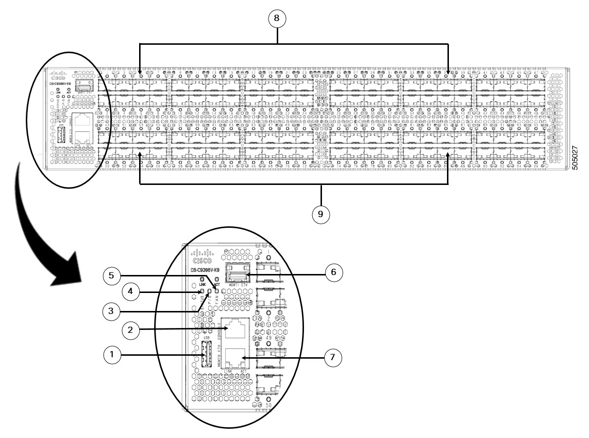
The Cisco MDS 9396V 64 Gbps 96 Port two rack unit (2 RU) Fibre Channel switch provides high-speed Fibre Channel connectivity in the SAN. The switch is built around the Cisco 64 Gbps FC ASIC with integrated analytics and telemetry capabilities. This Non-Volatile Memory Express (NVMe)-ready switch allows seamless transition to Fibre Channel Non-Volatile Memory Express (FC-NVMe) workloads whenever available without any hardware upgrade in the SAN. This high-density, highly reliable, scalable, enterprise-class semi-modular switch is ideal for medium to large departmental SANs.

Read the Regulatory and Compliance Safety Information document before installing the Cisco MDS 9396V Switch.

The Cisco MDS 9396V switch has the following major features:

  • 96 x 64/32/16/8 Gbps line rate Enhanced Small Form-Factor Pluggable (SFP+) ports provide an aggregate bandwidth of 6 Tbps per switch for highly scalable designs in hyperscale environments that drive several thousands of virtual machine instances within a rack. This switch provides four ports which can be configured with up to 16000 Buffer-To-Buffer (B2B) credits that can be connected to remote data centers as far as 512 km (318 miles) using native Fibre Channel connectivity at 64 Gbps speeds. These distances become even greater at lower speeds.

  • Provides consistent 64 Gbps performance for every Fibre Channel port on the switch.

  • Provides higher availability and reliability than the previous generations of Cisco MDS 9000 Series Switches. Additionally, port channel link members can be used across the four 24-port port groups providing additional high availability.

  • Provides minimum configuration option of 48 x 64/32/16/8 enabled Fibre Channel ports in the base variant, which can be enabled in increments of 16 ports to up to complete 96 port capacity. This allows four possible configurations of 48, 64, 80, and 96 ports.

  • Supports enterprise-class features such as Dynamic Ingress Rate Limiting (DIRL), Virtual SAN (VSAN) domains for traffic segregation, Access Control Lists (ACLs) for hardware-based intelligent frame processing, Smart Zoning, fabric-wide Quality of Service (QoS), IVR, and 1 Tbps multi-member port-channels. Traffic encryption is optionally available to meet stringent security requirements.

  • Provides intelligent diagnostics tools such as Inter-Switch Link (ISL) diagnostics, HBA diagnostics compatible with leading HBA vendors, Read Diagnostic Parameters, protocol decoding, network analysis tools, integrated Cisco Call Home, and Online Health Monitoring System (OHMS).

  • Supports the Virtual Machine Identifier (VMID) feature that provides visibility into virtual machines that are accessing the storage devices in the fabric.

  • Supports Cisco NX-API capabilities.

  • Supports Python 3 interpreter. This allows the creation of user-customizable scripts.

  • Provides hardware protection from malicious physical attacks by securing access to critical components such as the bootloader, system image loader, and Joint Test Action Group (JTAG) interface.

Chassis Components

This section describes the different components of the chassis.

Front View

The following figure shows the front view of a Cisco MDS 9396V Switch:

Figure 1. Front View of the Cisco MDS 9396V Switch

1

USB port

5

Fan status LED

2

Serial console port

6

MGMT1 Eth port

3

Power supply status LED

7

MGMT0 Eth port

4

System status LED

8, 9

Base Fibre Channel ports

Ports are numbered fc1/1 to fc1/96.

Rear View

The following figure shows the rear view of a Cisco MDS 9396V Switch:

Figure 2. Rear View of the Cisco MDS 9396V Switch

1

Power supply unit fan

5

Power supply units (2)

2

Power supply unit handle

6

Chassis fan modules (3)

3

Power receptacle

7

Fan module locking latch

4

Power supply unit locking latch

Figure 3. Rear Panel Slot Numbering of Cisco MDS 9396V Switch
1 Power supply unit slot 2 Chassis fan module slot

Grounding Point

The rear of the Cisco MDS 9396V switch also contains the grounding point which is located under a label.

Figure 4. Grounding Point
1 Grounding point 3 Port side of the switch
2 Rack mount holes

Switch LEDs

The following table describes the chassis LEDs for Cisco MDS 9396V switches:

Indicator Location Function Color Status State
Power LED Front panel of chassis Chassis power/Health Off Off

Either of the following conditions exists:

  • The system is not receiving sufficient power from the PSUs.

  • The operating system is not running.

Green Solid On Both PSUs are installed and operating
Red Solid On

Either of the following conditions exists:

  • A PSU has failed.

  • A PSU has been removed.

Status LED Front panel of chassis System Status Green Solid On All diagnostics have passed, Cisco NX-OS is running and the system is operational.
Orange Solid On

Any of the following conditions exist:

  • The system is running bootup diagnostics.

  • The system is booting.

  • A minor temperature threshold is currently exceeded.

Red Blinking

Mismatched airflow direction was observed in one of the following modules:

  • Fan modules—The switch will shut down in 20 seconds.

  • PSUs—The switch will power down after 10 minutes.

Solid On

One of the following conditions exists:

  • A diagnostic test failed or another fault occurred during bootup.

  • A major temperature threshold is currently exceeded.

Fan Status On the front panel Fan health Green Solid On Fan is operating normally
Red Solid On Fan has failed or Fan has been removed.
Faceplate of each fan module Fan tray health Green Solid on Fan module is operating normally.
Red Solid on The fan in the fan module has failed.
PSU Status Faceplate of each PSU PSU input/output Green Off No input to the PSU.
Solid on PSU output is OK.
Blinking PSU output is not OK, but input is OK.
PSU Operation Amber Solid on

One of the following conditions exists in the PSU:

  • Over voltage

  • Over current

  • Over temperature Fan failure.

Blinking PSU has a fault but is still operational.
Off PSU is operating normally.

The following table describes the Ethernet port LEDs for Cisco MDS 9396V switches.

LED Position Status State
Left Off There is no link.
Solid Green Indicates a physical link.
Right Off There is no activity.
Blinking Green Indicates activity.

The following table describes the Fibre Channel port LEDs for Cisco MDS 9396V switches.

Status State
Solid Green The link is up.
Regular Blinking Green The port beacon is active.
Intermittent Blinking Green The link is up (indicates that there is traffic on the port).
Solid Orange SFP is absent or the port is disabled by the software.
Blinking Orange A fault condition exists.
Off No link.

Fan Modules

The Cisco MDS 9396V Multilayer Fabric switch supports three hot-swappable fan modules in N+1 mode. Each fan module includes two counter rotating impellers, maximizing reliability, performance and cooling efficiency. For normal operation, the switch requires two fan modules. This allows the switch to continue to operate nondisruptively if a single fan module is removed or fails, provided that the preset temperature thresholds are not exceeded.

Temperature control within the Cisco MDS 9396V switch is dependent on airflow created by the fan modules. The switch has internal temperature sensors that can shut down the system if the temperature at different points within the chassis exceeds safety thresholds. If one fan module is removed from the switch or fails, the remaining two fan modules will immediately run at full speed. If two fan modules are removed from the switch or fail, the switch will shut down after 80 seconds to prevent potential undetectable overheating. To display temperature threshold values, use the show environment temperature command.

The direction of the airflow of all fan modules installed in a switch must be the same. If all fan modules do not have the same airflow direction, then the switch is powered down after 20 seconds. Airflow direction through a fan module is denoted by a color on the module faceplate:

  • Red – indicates port-side intake airflow (DS-C96V-FAN-I)

  • Blue – indicates port-side exhaust airflow (DS-C96V-FAN-E)

To display the current status of the fan modules in the switch through the CLI, use the show inventory fan command.

Figure 5. Cisco MDS 9396T Fan Modules

The following table describes the status LED located on each fan module.

LED Status
Green Fan is operating normally
Red One or more fans in the module is faulty

The airflow direction of the PSUs must match the direction of the fan modules. If the airflow of a newly inserted power supply unit is different from that of the fan modules, the newly inserted incompatible PSU will be disabled to avoid affecting system thermal performance.

For information about replacing and installing fan modules, see Installing and Removing Components.

Power Supplies

The Cisco MDS 9396V Multilayer Fabric switch supports two hot-swappable power supply units (PSUs). Each unit has a power receptacle, a status LED on the faceplate, and a handle for inserting and removing the unit from the chassis. The Cisco MDS 9396V switch requires a minimum of 1 PSU for normal operation and 2 PSUs for normal operation with PSU redundancy. In the event of a PSU or AC supply (in grid redundant mode) failure, the system will continue to run. PSUs are hot-swappable and can be individually replaced without shutting down the system.

The three types of PSUs supported with Cisco MDS 9396V are:

  • Blue: 1.4 KW AC port-side exhaust power supply (DS-CAC-1400W-E)

  • Red: 1.4 KW AC port-side intake power supply (DS-CAC-1400W-I)

  • Red: 2 KW HVAC/HVDC port-side intake power supply (DS-CHV-2000W-I)

Figure 6. Cisco MDS 9396V AC PSU

1.4 KW AC port-side exhaust power supply (DS-CAC-1400W-E)
1.4 KW AC port-side intake power supply (DS-CAC-1400W-I)

Figure 7. Cisco MDS 9396V DC PSU

2 KW HVAC/HVDC port-side intake power supply (DS-CHV-2000W-I)

For information about replacing and installing power supply units, see Installing and Removing Components.

Cabinet and Rack Requirements

This section provides the Cisco MDS 9000 Series switches requirements for the following types of cabinets and racks in an external ambient air temperature range of 0 to 40°C:

  • Standard perforated cabinets

  • Solid-walled cabinets with a roof fan tray (bottom-to-top cooling)

  • Standard open racks

  • Telco racks


Note


If you are selecting an enclosed cabinet, we recommend one of the thermally validated types listed above: standard perforated or solid-walled with a fan tray.


General Requirements

The cabinet or rack must be a standard 19-in. four-post EIA cabinet or rack, with mounting posts that conform to English universal hole spacing per section 1 of ANSI/EIA-310-D-1992. See the Requirements Specific to Perforated Cabinets and Requirements Specific to Solid-Walled Cabinets.

The cabinet or rack must also meet the following requirements:

  • The minimum vertical rack space per chassis should be 2 RU (rack unit), equal to 1.75 in. (4.4 cm).

  • The width between the rack-mounting rails must be at least 17.75 in. (45.1 cm). This is the distance between the two front rails.

  • For four-post EIA cabinets (perforated or solid-walled):

    • The distance between the front door and front mounting posts should be a minimum of 3 in. (7.6 cm) to allow for the bend radius of FC port fibre-optic patch cables.

    • The distance between the outside face of the front mounting rail and the outside face of the back mounting rail should be 23.5 to 34.0 in. (59.7 to 86.4 cm) to allow for installation with the Cisco rack mounting kit.

    • There should be a minimum of 2.5 in. (6.4 cm) of clear space between the side edge of the chassis and the side wall of the cabinet. No sizable flow obstructions should be immediately in the way of the chassis air intake or exhaust vents.

    • The distance between the rear of the chassis and the perforated rear door of the cabinet (required for airflow in the cabinet, if used) should be a minimum of 3.0 in. (7.6 cm).

    • The airflow and cooling are adequate and there is sufficient clearance around the air vents on the switch, as described in Technical Specifications. This is particularly important to verify if you are installing the switch in an enclosed cabinet.

    • No clearance is required between the chassis and the sides of the rack or cabinet (no side airflow).

    • The rack meets the minimum rack load ratings per rack unit (RU) listed in the following table.

Rack Type MDS 9396V
EIA (4-post) 7.5 lb
  • Cisco MDS 9396V switches are compatible with Cisco racks (such as Cisco R42612) and PDUs. Optional jumper power cords are available for use in a cabinet.

Requirements Specific to Perforated Cabinets

In addition to the requirements listed in the General Requirements for Cabinets and Racks section, perforated cabinets must meet the following requirements:

  • The front and rear doors must have at least a 60 percent open area perforation pattern, with at least 15 sq. in. of open area per rack unit of door height.

  • We recommend that the roof be perforated with at least 20 percent open area, unless the cabinet only contains Cisco MDS 9396V switch, in which case the roof does not have to be perforated.

  • We recommend an open or perforated cabinet floor to enhance cooling but it is not required.

Reference Perforated Cabinet

A perforated cabinet that conforms to the above requirements is available from Rittal Corporation:

Rittal Corporation One Rittal Place Springfield, OH 45504
Phone: (800) 477-4000
Cabinet P/N: Rittal 9969427
Cabinet description: PS-DK/OEM Cabinet Assembly, 1998 x 600 x 1000 (H x W x D) (42U)

Requirements Specific to Solid-Walled Cabinets

In addition to the requirements listed in the General Requirements for Cabinets and Racks section, solid-walled cabinets must meet the following requirements:

  • The rack must have a roof-mounted fan tray and an air-cooling scheme in which the fan tray pulls air in at the bottom of the cabinet and sends it out from the top, with a minimum airflow of 849.5 m3/h exiting the cabinet roof through the fan tray, should be available.

  • The front and rear doors, and side panels, must be installed and nonperforated so that air flows predictably from bottom to top.

  • The overall cabinet depth should be 36 to 42 in. (91.4 to 106.7 cm) to allow the doors to close and to facilitate adequate airflow.

  • The open area of the floor air intake must be a minimum of 150 sq. in. (968 sq. cm).

  • The lowest piece of equipment should be installed at a minimum of 1.75 in. (4.4 cm) above the floor openings to prevent blocking the floor intake.