Overview
The Cisco N9K-C9332D-GX2B switch is a 1-rack unit (RU), fixed-port switch designed for spine-leaf-APIC deployment in data centers.
This switch includes these ports:
-
400-Gigabit QSFP-DD ports (32)
-
10-Gigabit SFP+ ports (2)
-
Management ports (one 10/100/1000BASE-T port and one SFP port)
-
Console port (RS-232)
-
USB port
Default port-profile information for this switch:
-
Default port profile (Leaf): 24 downlinks and 8 fabric links + 2x1/10G downlinks
Leaf/Spine role considerations:
-
The default role of the switch is as a leaf switch.
-
The default fabric links (ports 25-32) must be used for initial switch discovery via another switch.
-
To change the switch from the default role: the node appears as a discovered device in the fabric inventory view, set the role of the switch (spine or leaf), and the switch automatically reboots to come up in the configured role.
-
If you connect a default spine (i.e., a dual role switch that by default is a spine, such as N9316D-GX) directly to an APIC, the change of the role to leaf is performed automatically by APIC, as well as the reboot. After that, the node appears in “Nodes pending registration.” Register the node.
 Note |
From ACI release 6.1(2) and later, you can change the role of any undiscovered switch before the switch is discovered using this CLI command:
|
Note |
The For more information about using this CLI command, see the Cisco APIC Getting Started Guide, Release 6.1(x). |
Discovery considerations:
-
Discovery via APIC – use the default downlink ports.
-
Spine discovery – use the default fabric links (ports 25-32) and convert the switch to spine (reboot is required).
-
Leaf discovery via spine – use the default fabric links (ports 25-32).
-
Sub-leaf discovery via leaf – use the default fabric links (ports 25-32).
-
Multi-Pod first spine discovery via IPN – Connect the IPN to one of the default fabric links (ports 25-32). Ensure the spine has at least one leaf node connected to it.
This switch includes these user-replaceable components:
-
Fan modules (6) with these airflow choices:
-
Port-side exhaust fan module with blue coloring (NXA-SFAN-35CFM-PE)
-
Port-side intake fan module with burgundy coloring (NXA-SFAN-35CFM-PI)
-
-
Power supply modules (two—One for operations and one for redundancy [1+1]) with these choices:
-
1500-W port-side intake AC power supply with red coloring (NXA-PAC-1500W-PI)
-
1500-W port-side exhaust AC power supply with blue coloring (NXA-PAC-1500W-PE)
-
1100-W port-side intake DC power supply with red coloring (NXA-PDC-1100W-PI)
Fan information:
-
-
All fan modules and power supplies must use the same airflow direction.
-
Each fan module has two rotors. The switch can function normally if one rotor inside any one fan module fails. In case of more than one rotor failure, the switch will issue a warning and power down in 2 minutes.
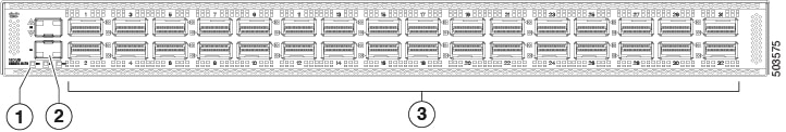
The figure shows the switch features on the port side of the chassis.
|
1 |
LEDs |
3 |
400-Gigabit QSFP-DD ports (32) |
|
2 |
10-Gigabit SFP+ ports (2) |
To determine which transceivers, adapters, and cables support this switch, see the Cisco Transceiver Modules Compatibility Information document.
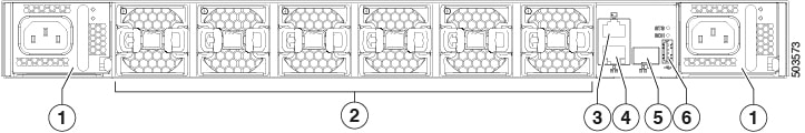
The figure shows the switch features on the power supply side of the chassis.
|
1 |
Power supply modules (1 or 2) (AC power supplies shown) with slots numbered 1 (left) and 2 (right) |
4 |
Management port (RJ45) |
|
2 |
Fan modules (6) with slots numbered from 1 (left) to 6 (right) |
5 |
Management port (SFP) |
|
3 |
Console port |
6 |
USB port |
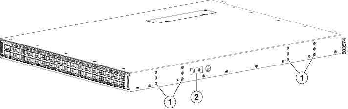
The figure shows the side of the chassis.
|
1 |
Screw holes for mounting brackets |
2 |
Grounding pad |
The fan and power supply modules are field replaceable. You can replace one fan module or one power supply module during operations as long as the other modules are installed and operating. If you have only one power supply installed, you can install the replacement power supply in the open slot before removing the original power supply.
Note |
All fan and power supply modules must have the same direction of airflow, or the switch can overheat and shut down. |
 Caution |
If the switch has port-side intake airflow (burgundy coloring for fan modules), locate the ports in the cold aisle. If the switch has port-side exhaust airflow (blue coloring for fan modules), locate the ports in the hot aisle. If you locate the air intake in a hot aisle, the switch can overheat and shut down. |
Optics specifications
Note |
IMPORTANT: From ACI Release 6.1(3), the switch uses NXA-PDC-1500W-PE PSUs and supporting fans. If you downgrade the switch software, the switch will power down. To avoid this failure
|
Use the supported power supplies and fans listed in the table. For power supply and fan remove and install procedures, see Replacing a Fan Module.
|
Power Supply |
Fan |
MACSec -Enabled |
Ambient Temperature Limit |
Optics Power (W) Consumption |
|---|---|---|---|---|
|
NXA-PAC-1500W-PI |
NXA-SFAN-35CFM-PI |
8 ports |
40 °C |
Ports 1-32: Max. 12W per port |
|
NXA-PAC-1500W-PI |
NXA-SFAN-35CFM-PI |
4 ports |
40 °C |
Ports 1-28: Max. 12W per port Ports: 29-32: Max. 20W per port |
|
NXA-PAC-1500W-PI |
NXA-SFAN-35CFM-PI |
0 ports |
40 °C |
Ports 1-24: Max. 12W per port Ports: 25-32: Max. 20W per port |
|
NXA-PAC-1500W-PE |
NXA-SFAN-35CFM-PE |
8 |
30 °C |
Ports 1-32: Max. 12W per port |
|
NXA-PAC-1500W-PE |
NXA-SFAN-35CFM-PE |
4 |
30 °C |
Ports 1-28: Max. 12W per port Ports: 29-32: Max. 20W per port |
|
NXA-PAC-1500W-PE |
NXA-SFAN-35CFM-PE |
0 |
30 °C |
Ports 1-24: Max. 12W per port Ports: 25-32: Max. 20W per port |
|
NXA-PDC-1100W-PI |
NXA-SFAN-35CFM-PI |
8 |
40 °C |
Total power available for optics: 200W Ports 1-32: Max. 12W per port |
|
NXA-PDC-1100W-PI |
NXA-SFAN-35CFM-PI |
4 |
40 °C |
Total power available for optics: 200W Ports 1-28: Max. 12W per port Ports 29-32: Max. 20W per port |
|
NXA-PDC-1100W-PI |
NXA-SFAN-35CFM-PI |
0 |
40 °C |
Total power available for optics: 200W Ports 1-24: Max. 12W per port Ports 25-32: Max. 20W per port |
|
NXA-PDC-1500W-PE |
NXA-SFAN-35CFM-PE |
8 |
30 °C |
Ports 1-32: Max. 12W per port |
|
NXA-PDC-1500W-PE |
NXA-SFAN-35CFM-PE |
4 |
30 °C |
Ports 1-28: Max. 12W per port Ports: 29-32: Max. 20W per port |
|
NXA-PDC-1500W-PE |
NXA-SFAN-35CFM-PE |
0 |
30 °C |
Ports 1-24: Max. 12W per port Ports: 25-32: Max. 20W per port |
 Feedback