Overview of Cisco
Modeling Labs
Cisco Modeling Labs
Cisco Modeling Labs is a scalable and extensible software platform that enables operators, engineers, network designers, and architects to design Cisco-based networks and run simulations using virtual versions of selected Cisco operating systems. Cisco Modeling Labs comprises the Cisco Modeling Labs server and the Cisco Modeling Labs client. Together, they provide a sandbox environment that facilitates the design, configuration, visualization, and simulation of network topologies quickly and efficiently.
- Cisco Modeling Labs server: A shared resource containing the capability to initiate topologies using installed virtual images.
- Cisco Modeling Labs client: A point-and-click GUI that simplifies topology creation and initial device configurations along with continuous updates. It also permits access to the Cisco Modeling Labs server functionality.
Scalability
Cisco Modeling Labs supports a maximum of 300 nodes.
Since many customers are building bigger and bigger topologies, the previous 200 node limit has been increased to 300 nodes. Used in conjunction with Cisco Modeling Labs clustering capabilities, the 300 node limit allows Cisco Modeling Labs customers to significantly improve their ability to run large simulations.
 Note | However, this expanded capacity is limited by the underlying compute infrastructure. A simulation of 300 nodes may only be achieved when the bulk of the virtual nodes only require single vCPU allocations. The 300 node capacity might not be attained when employing node images requiring multi-vCPU assignments. Refer to the Cisco Modeling Labs resource calculator for further details. |
Cisco Modeling Labs Client
For further information on the Cisco Modeling Labs client, see Using the Cisco Modeling Labs Client Overview.
Virtual Images
See Release Notes for Cisco Modeling Labs 1.3 for more information on Cisco virtual software supported features.
Cisco Modeling Labs Server Requirements
This section details the hardware and software requirements for installing the Cisco Modeling Labs server.
The following table lists hardware requirements that are based on the number of virtual nodes used.
| Requirement | Description |
|---|---|
| Disk Space | 500 GB minimum |
| Chip Set | Intel® with Intel virtualization technology VT-x and Extended Page Tables (EPT) |
| Hypervisor | VMware ESXi 5.1 U2, ESXi 5.5 U1, ESXi 6.0 (Build 2494585), ESXi 6.5 (Build 4564106) |
| Server type for OVA package | Any server with Intel virtualization technology VT-x and Extended Page Tables (EPT) |
| Server type for ISO package |
Supported only on Cisco UCS® C220 M4 and C460 M4 with local storage |
| Server Recommendation | Cisco UCS C-Series |
The recommended servers for Cisco Modeling Labs are the Cisco UCS C220 M4 and Cisco C460 M4 servers.
For more information on UCS servers, see the applicable data sheets at http://www.cisco.com/c/en/us/products/servers-unified-computing/ucs-c-series-rack-servers/index.html.
For bare metal installations, Cisco Modeling Labs ISO package is certified only with the Cisco UCS C220 M4 and Cisco C460 M4 servers.
Sizing the Server: Number of Cores and Memory Requirements
The general rule of thumb is three virtual nodes to one physical core CPU for simulation of 49 nodes and below, and two virtual nodes to one physical core CPU for 50 nodes and above.
Note | In order to size the Cisco Modeling Lab Server resources, you must use the Cisco Modeling Labs resource calculator available at http://www.cisco.com/go/cml |
| Requirement | Description | ||
|---|---|---|---|
| VMware | |||
| VMware vSphere | Any of the following:
|
||
| Browser | Any of the following:
|
|
Name |
Description |
||||
|---|---|---|---|---|---|
|
Intel Hyper-Threading Technology |
|
||||
|
Intel VT |
|
||||
|
Intel VT-d |
|
Cisco Modeling Labs Framework
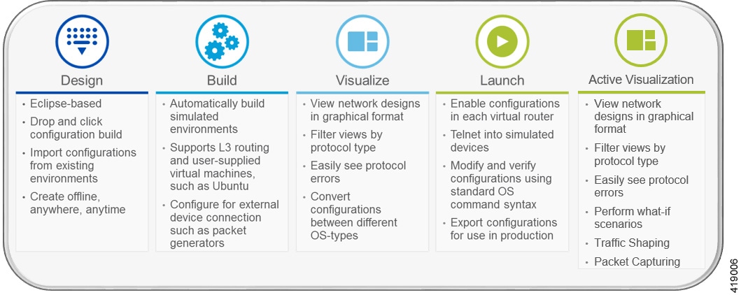
Cisco Modeling Labs includes numerous features that enable you to create and simulate small and large network designs. This user guide is organized in a task-based format where the main features are grouped into four sections that are referred to as phases.
The following items describe each phase which should help you determine, which section to refer to when using this guide:
- Design: This phase includes the tasks for creating a network topology. You use a blank canvas to create topologies from scratch or import existing network topologies. You can also adjust where and how interfaces are used on each device.
- Build: This phase includes the tasks associated with configuring routers, external connections, and servers, creating the required configurations, setting up interfaces, IP addressing, and routing protocols for the virtual routers. There are several ways to create these configurations. You can use the AutoNetkit functionality to set up the initial configuration, or you can input your own configuration details. Whatever configurations you create in this phase will be the configurations that the Cisco Modeling Labs server will use when it initiates the node simulations.
- Visualization: This phase is optional and operates only if you use AutoNetkit to create your configurations during the build phase. It includes the tasks related to running visualization scenarios of your network design and configuration. It provides visual views of your topology whereby you can see how the nodes will interact with each other in specific circumstances, including physical set up, as well as with specific routing protocols, such as IS-IS and OSPF. It also supports MPLS and BGP.
- Launch Simulation: This phase includes the tasks for initiating the nodes and making them active. Once the nodes are operational, you can use Telnet or SSH to connect to the consoles as you would connect to a router console. You can run connectivity tests and modify configurations. This is where the power of the product is realized: you can modify and test configurations as if you were on actual physical devices. In this phase, you can also save your configurations and extract them for sharing with others or save them and use them as reference when configuring the production network.
- Active Visualization: This phase includes the tasks related to running visualization scenarios of your network design and configuration. It provides visual views of your topology whereby you can see how the nodes will interact with each other in specific circumstances, including physical set up, as well as with specific routing protocols. In addition, traffic shaping allows you to control access to available bandwidth, to ensure that traffic conforms to the policies established for it, and to regulate the flow of traffic in order to avoid congestion that can occur when the sent traffic exceeds the access speed of its remote, target interface. The added ability to conduct packet captures is a valuable tool for troubleshooting connectivity issues within your network
Topology Node Count Changes
In previous releases of Cisco Modeling Labs, the capacity calculation rules were applied on a per-simulation basis. This meant that with a 35-node license, the largest topology that you could theoretically launch would be one with up to 35 Cisco virtual machines (not including 3rd party VMs or containers.) Any topology that exceeded the 35 nodes would be rejected, irrespective of the node’s run state.
Changes introduced in this release mean that the capacity calculation is now performed on a per-node basis. This means that you are now able to launch up to 35 nodes (assuming a 35 node license) of a much larger topology by selecting which nodes would be started. For example, if you have a 40 node topology, you are able to mark 5 out of the 40 as Excluded from launch.
Once started, you are able to stop nodes and start other nodes in the topology, as long as you remain within the total node count capacity of your license.
 Feedback