- Simulate the Topology Overview
- Determining When a Node is Fully Operational
- Cisco Modeling Labs Active Canvas
- Launch a Simulation
- Connect to a Simulation Node Console
Simulate the
Topology
Simulate the Topology Overview
The simulation phase is when you run the simulation of your topology design. The Simulation perspective provides a set of views that support the simulation phase. By comparison, the design and build activities occur in the Design perspective, which provides a set of views that support the design activity. Some views in the Simulation perspective can also be viewed in the Design perspective.
Simulation Perspectives and Views
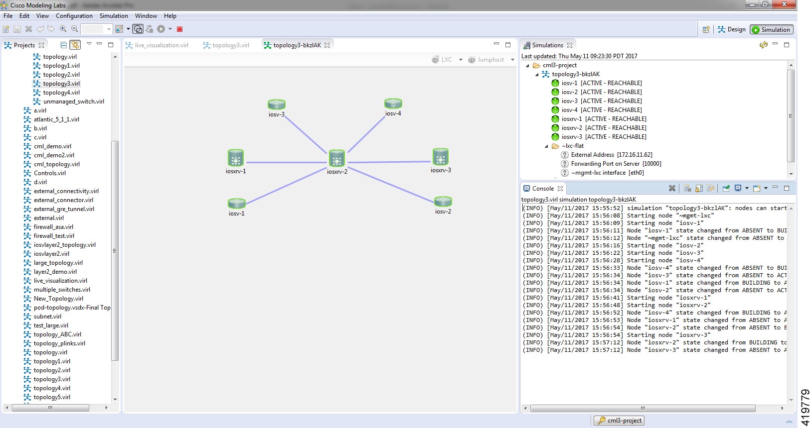
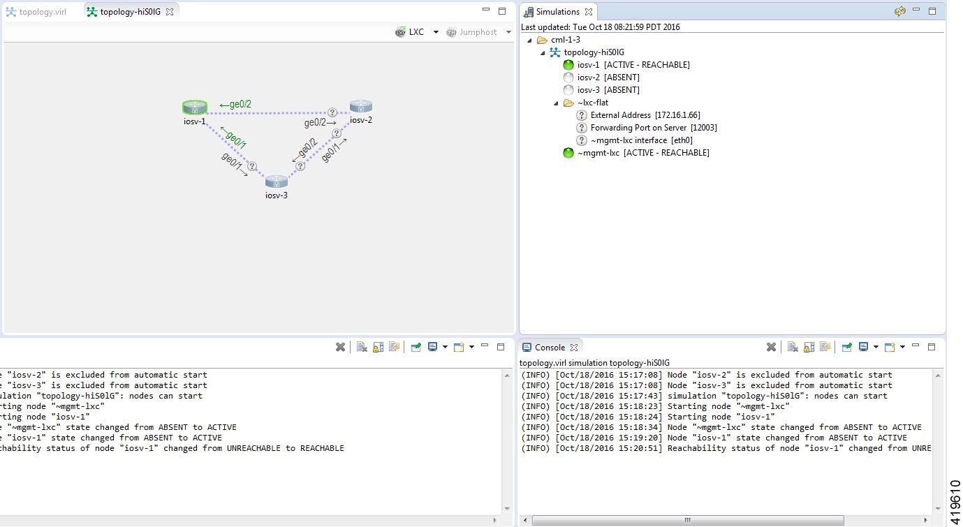
The main areas of focus within the Simulation perspective are the Simulations view and the Console view. The following figure highlights the Simulations and Console views for a running simulation.
 Note | To reset your current perspective to its original configuration when the workbench was first opened, right-click the perspective button and select Reset. |
Determining When a Node is Fully Operational
When a simulation starts up, the nodes move through a number of states before their configuration has been applied completely and they are deemed fully operational.
In this example, the log messages indicate when the nodes have transitioned from startup to the point where the configuration has been applied and the node is now reachable. The state is also reflected in the state marker shown in the Simulations view.
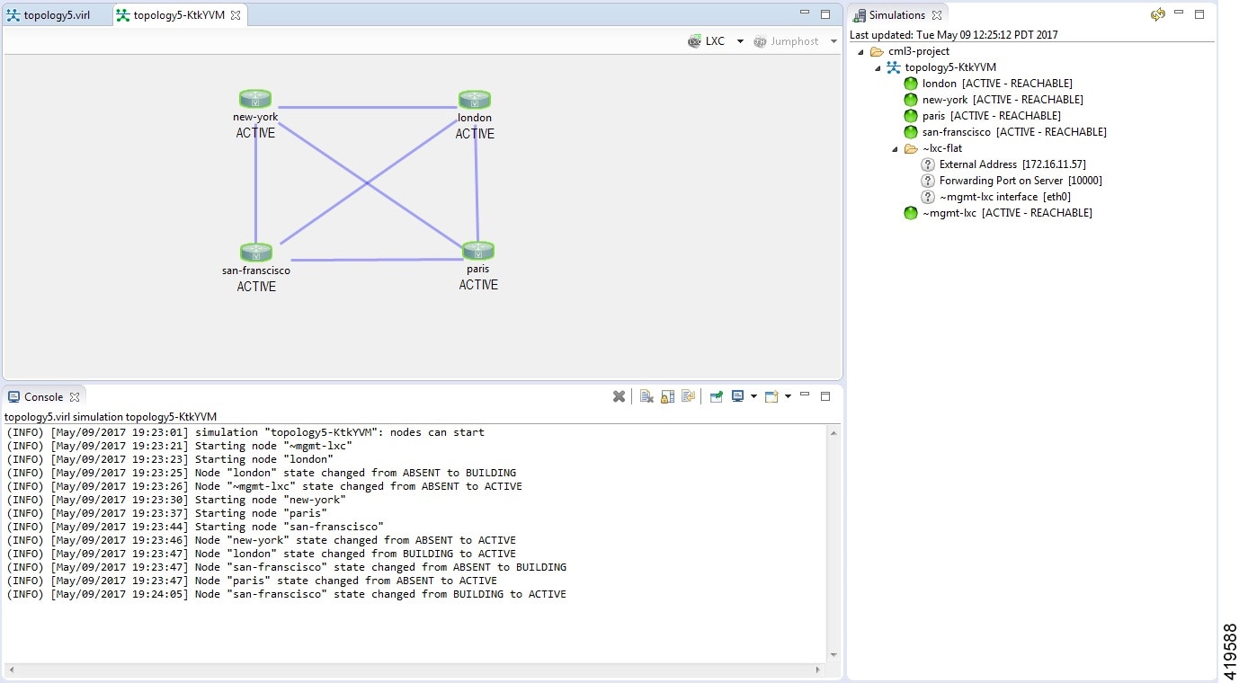
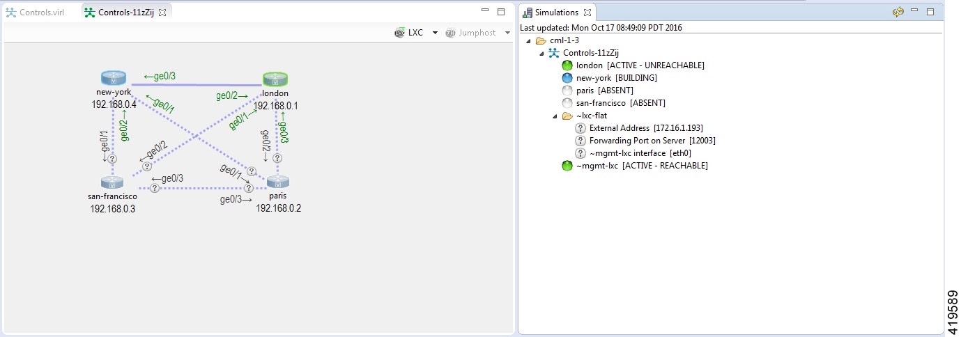
If the management interface is not configured or is in the shutdown state, the node will be shown as [ACTIVE - UNREACHABLE].
Cisco Modeling Labs Active Canvas
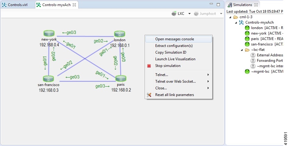
The Cisco Modeling Labs client provides users with an active canvas. When a simulation is started and the user switches to the Simulation perspective, a new window opens displaying the network diagram. As the virtual machines start up, the network diagram updates showing the current state of the simulation. Nodes change color depending on their current operational state.
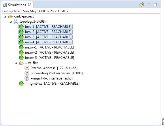
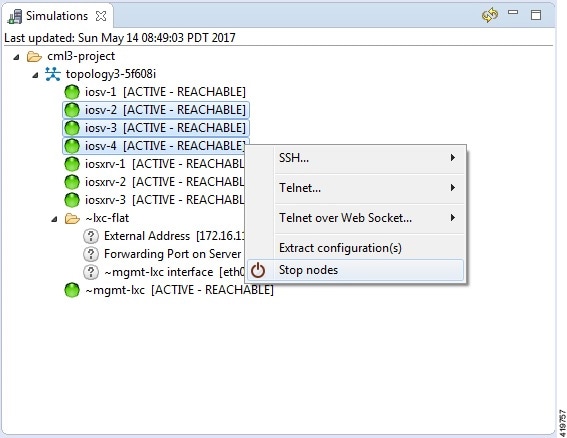
For example, the following figure shows nodes in green which indicates the Active state. Nodes in blue indicate the Build state. Grey nodes indicate the Absent state where a node is yet to be started or has been stopped.
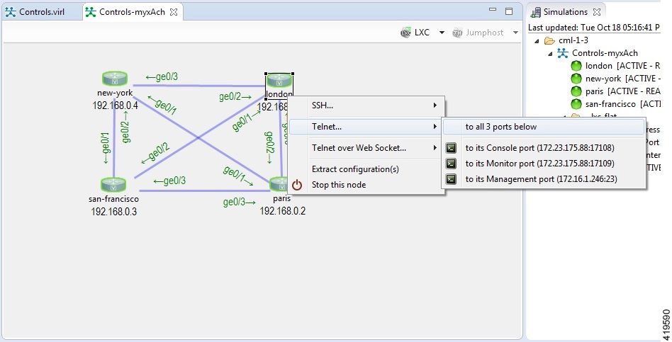
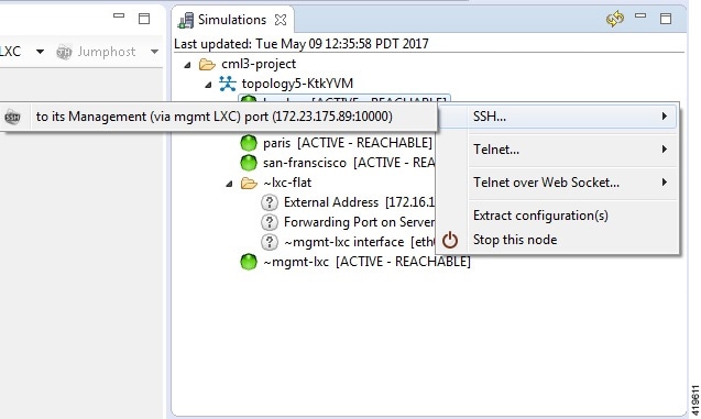
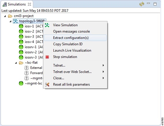
Once a node is in the active state, you can right-click on the node to perform operations such as opening an SSH or Telnet connection, extract the configuration of the specific node and stop/start the node.
Right-clicking on the background, without selecting a node, enables you to perform simulation-wide operations such as configuration extraction, launch the live visualization view, stop the simulation as well as resetting all link latency, jitter and packet-loss parameters that may be in operation.
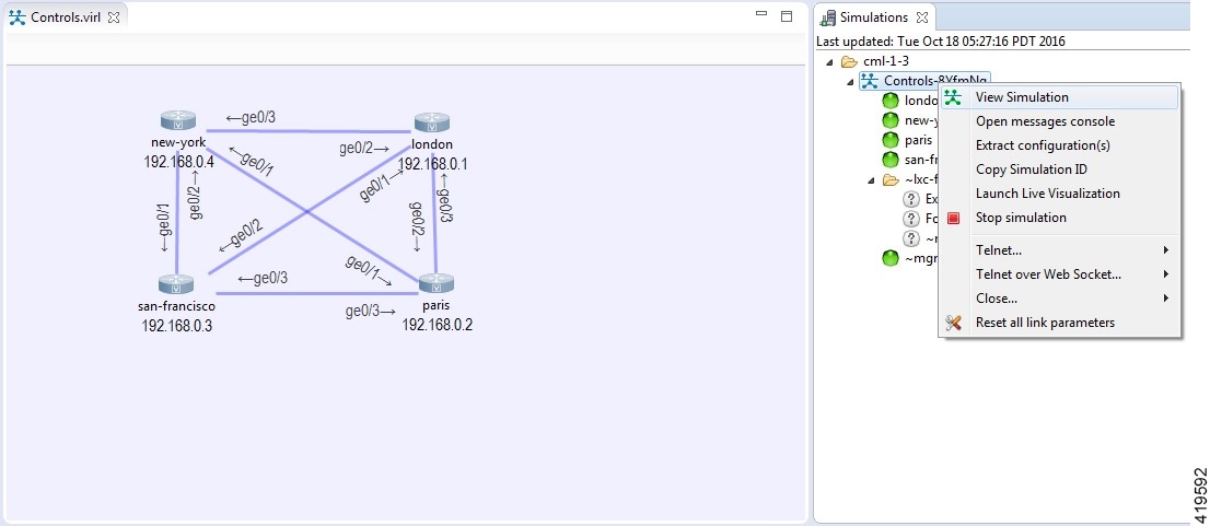
If the Simulations view is closed, it can be reopened by selecting the simulation from the simulations panel, right-clicking and selecting the View Simulation option.
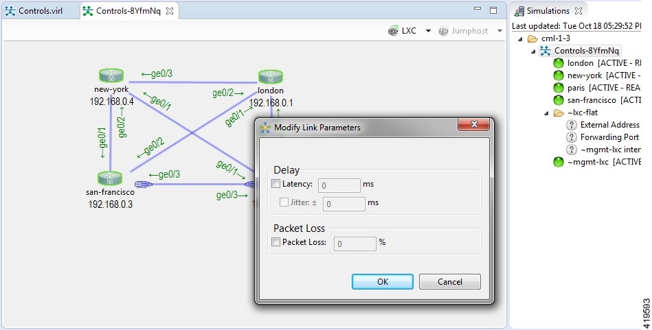
Link latency, jitter and packet-loss parameters can be set by selecting a link, right-clicking and using the Modify Link Parameters option.
Packet capture operations can be performed by selecting a link, selecting the interface (at one end of the link) and right-clicking to reveal the packet-capture control menu, as shown.
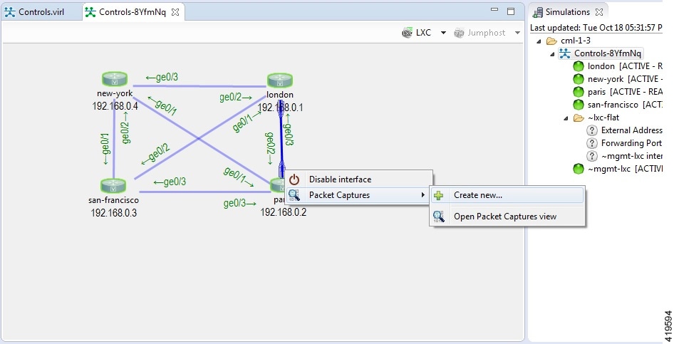
Once a packet capture has been configured, an icon will indicate that a packet-capture is present on the interface, with the Packet capture view listing the .pcap file that is available for analysis.
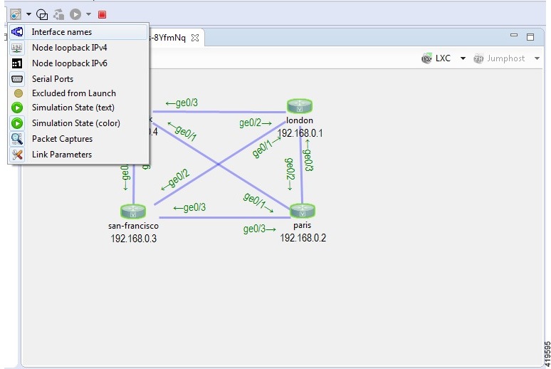
Additional diagram labels are now available including interface name, serial port number assignment and so on. These can be accessed from the Show Topology Labels icon on the Cisco Modeling Labs toolbar.
Launch a Simulation
To launch a simulation, complete the following steps.
-
Complete the topology design.
-
Complete the task of building the nodes and interfaces.
-
(Optional) Generate the configuration using AutoNetkit. 
Caution
When you manually make changes to a node configuration and bypass AutoNetkit autogeneration, those changes do not appear in the topology view of the Design perspective or Simulation perspective. For example, if you use the hostname command to change the host name from iosv-1 to Router-1 in the configuration, the node name in the topology view and in other related views remains as iosv-1. -
Open the desired topology.
Note
The topology should be open and visible in the Topology Editor. If you have multiple topologies open in the Topology Editor, simulation will launch for the currently active view.
Jumphost Virtual Machine (VM)
The jumphost VM is the default method for accessing the management network of a running simulation. The jumphost node runs in a separate simulation named ~jumphost and has two interfaces, eth0 in the project/user management network and eth1 in the FLAT network.
The purpose of the jumphost is to provide an access point into a simulated network that remains fixed, in that there is a single external IP address or port that the user can access. A user can access the jumphost and then access all the nodes inside the simulation.
-
A VM: Based on the server VM image type.
-
A Linux container: A lighter weight form of a jumphost. See Linux Container (LXC) for more information.
The VM implementation is costly in terms of the memory and CPU used when a jumphost is instantiated. However, since it is a full-blown server VM, there is value to it, in that you can install and run any application on it.
Linux Container (LXC)
An LXC provides a means of accessing a topology rather than having to create a full Linux server VM. All nodes in the network are connected to a hidden OOB management network that uses the first interface on each of the nodes.
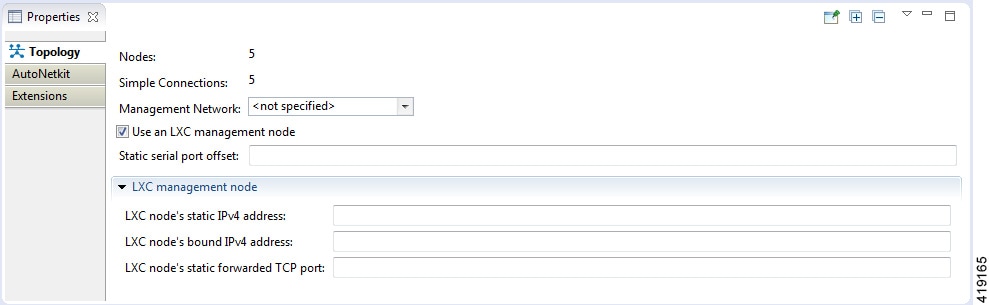
The LXC is automatically spun up and provides a jumphost point for access into the network. Connecting to the LXC means you can see the interfaces to the outside world and to the OOB network inside your simulation.
A connection is opened from the Cisco Modeling Labs client to a port on the Cisco Modeling Labs server and is forwarded to the LXC. The LXC, in turn, opens a connection to the Management Interface (Gi0/0) of the VM inside the simulation to the node instance.
Static Port Assignment to the LXC
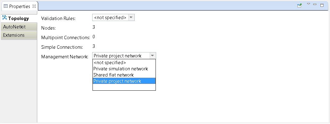
When the management network property Private simulation network is set, Cisco Modeling Labs assigns a random port for SSH port access to the LXC. However, you can statically define this by setting an extension on your topology.
To set an extension for your topology, complete the following steps.
| Step 1 | Click on the canvas to open the Topology tab in the Properties view. |
| Step 2 | Click the Extensions tab. |
| Step 3 | Click the Add new extension icon. The Edit Extension dialog box appears. |
| Step 4 | Enter the
following values:
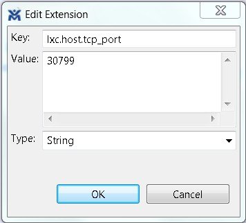 |
| Step 5 | Click OK to add the new extension. When the LXC starts, it will be bound to the TCP port specified in the new extension. |
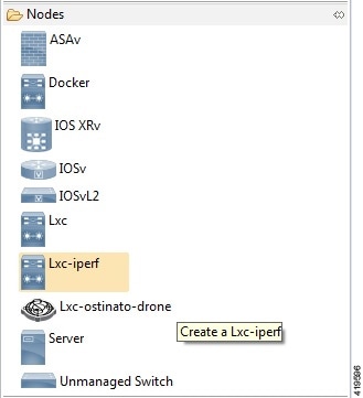
LXC iPerf Container
The LXC iPerf container provides a stripped down lightweight Linux container which has been loaded with the iPerf application available from Downloads - iPerf.
iPerf is a tool for the active measurement of the maximum achievable bandwidth on IP networks. It supports tuning of various parameters related to timing, buffers and protocols (TCP, UDP, SCTP with IPv4 and IPv6). For each test it reports the bandwidth, loss, and other parameters.
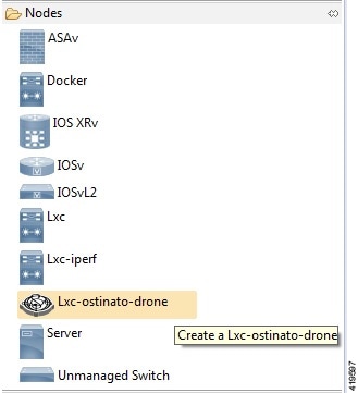
LXC Ostinato Container
An LXC container is available that contains the Ostinato packet traffic generator application. This application provides data-plane traffic generation capabilities. The Ostinato drone (generator) is used in combination with the Ostinato GUI. The GUI can be obtained from Downloads – Ostinato.
Note | Telnet does not work. |
Note | The Ostinato drone application should not be installed on the host system as the version in the repositories cannot be executed in the LXC. |
Launch a Phased Simulation
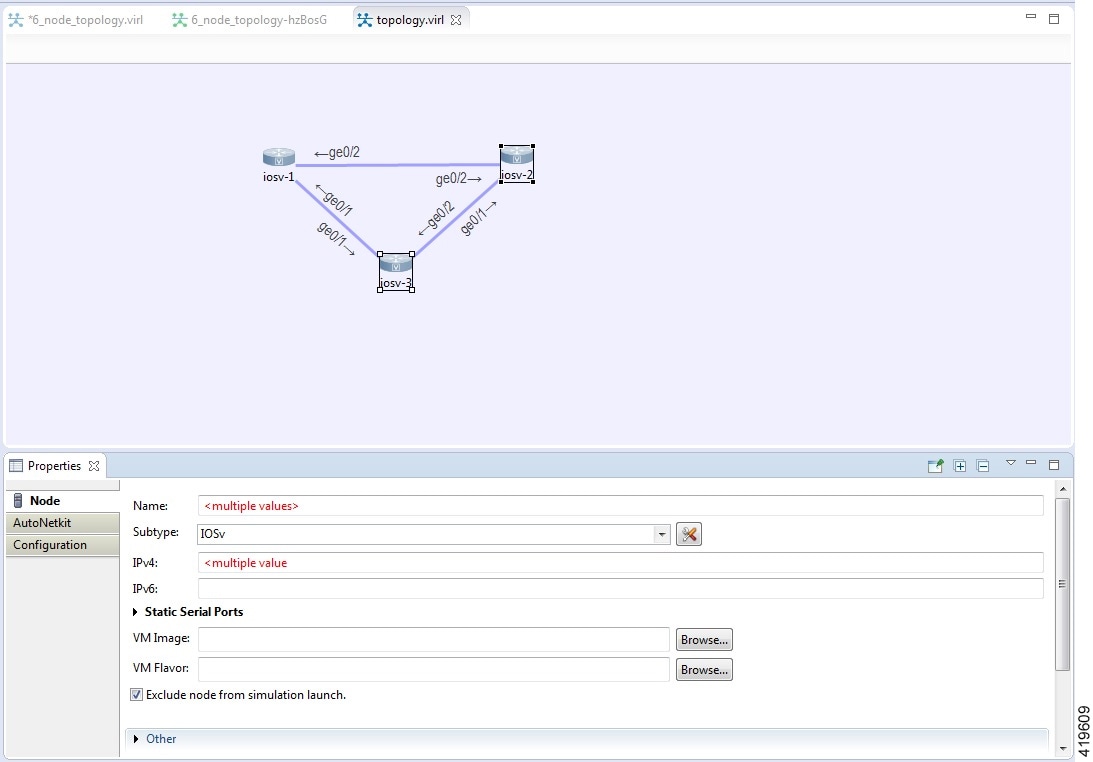
On occasions, you may need to start your simulation in phases rather than having all nodes launched at the same time. This functionality is facilitated by the Exclude node from simulation launch check box, which allows you to pick and choose which nodes to start.
To launch a phased simulation, complete the following steps.
| Step 1 | With the applicable topology open, click on the canvas and move the selection area over the nodes to be excluded from the running simulation. (Alternatively, you can double-click a specific node, hold down the Shift key, and select the remaining nodes.) The view opens. | ||
| Step 2 | In the
view, check the
Exclude node from simulation
launch
check box.
 | ||
| Step 3 | Save your
topology using Ctrl-S.
| ||
| Step 4 | From the toolbar, click the Build Initial Configurations button to build the node configurations. | ||
| Step 5 | From the
toolbar, click the
Launch
Simulation button.
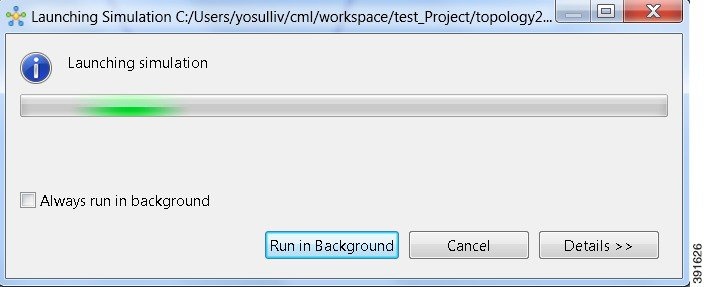
The
simulation launches.
 |
Launch Simulation Options
In circumstances where you need to run a simulation for a specified time frame or you want to specify your own name for a simulation, complete the following steps:
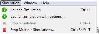
| Step 1 | From the menu bar, choose the Simulation button. | ||||
| Step 2 | From the list,
click
Launch Simulation with
Options.
 The Launch Simulation dialog box is displayed. 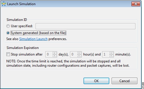 | ||||
| Step 3 | If you want to
specify your own name or label for the simulation, check the
User
Specified radio button. Otherwise, leave the default
System generated
( based on a file) radio button checked.
| ||||
| Step 4 | Set a time
duration for the simulation by entering details for
Days,
Hours, and
Minutes by
using either the up and down arrows or entering the values directly. Click
OK to apply
your time limit to the simulation.
The
simulation launches.
|
Reset the Time Limit on a Running Simulation
You can extend or reduce the time limit set for a running simulation in the User Workspace Management interface. To do this, complete the following steps.
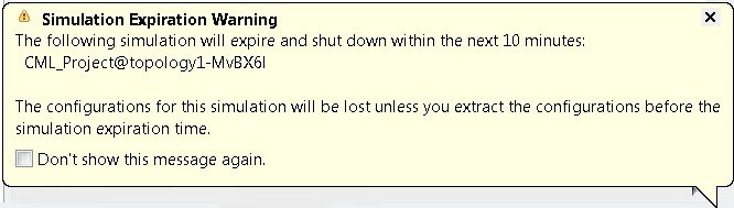
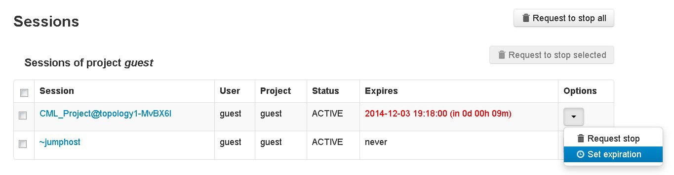
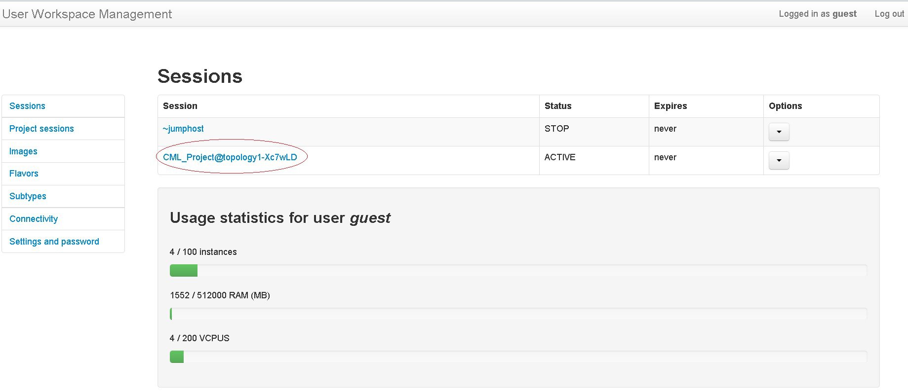
| Step 1 | Log in to the User Workspace Management interface. On the Overview page, information on running simulations is displayed. Move to the applicable simulation under the Session heading. If your simulation is due to expire in ten minutes or less, the simulation name is displayed in red. |
| Step 2 | Under the
Options
column, click the down arrow and click
Set expiration.
 |
| Step 3 | The
Set expiration
for session page is displayed. In the date and time field, enter either a
new expiration date and time, a date only, or a time only for the simulation.
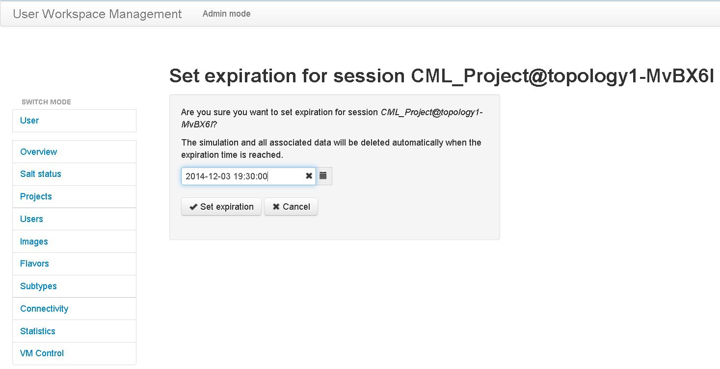 |
| Step 4 | Click Set expiration to save the changes. The time limit for the simulation is updated. |
Control Interface States
Note | This changes the state of the underlying communication infrastructure, not the interface state of the virtual machine. |
To control the state of an interface, complete the following steps.
| Step 1 | Log in to the
User Workspace
Management interface.
| ||
| Step 2 | On the Overview page, under Sessions, choose the applicable running session. A list of active virtual machines and interfaces is displayed. | ||
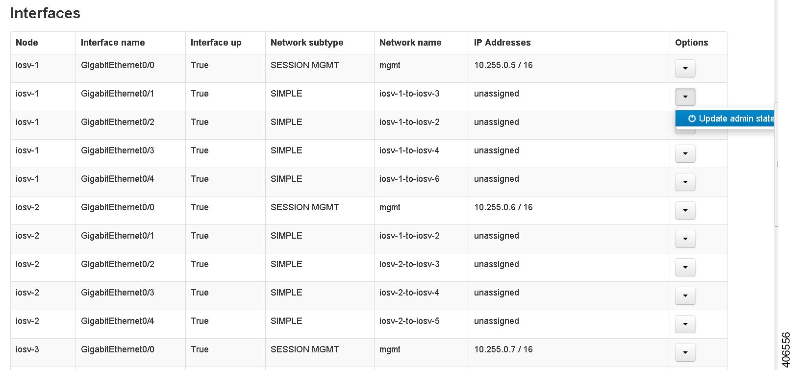
| Step 3 | Scroll down to the Interfaces section and choose the applicable virtual machine. | ||
| Step 4 | From the
applicable
Options
drop-down list, click
Update admin
state.
 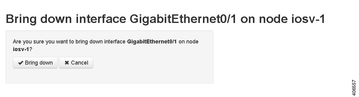 | ||
| Step 5 | Click
Bring down
to bring down the network interface.
A message
is displayed indicating that the interface has been brought down.
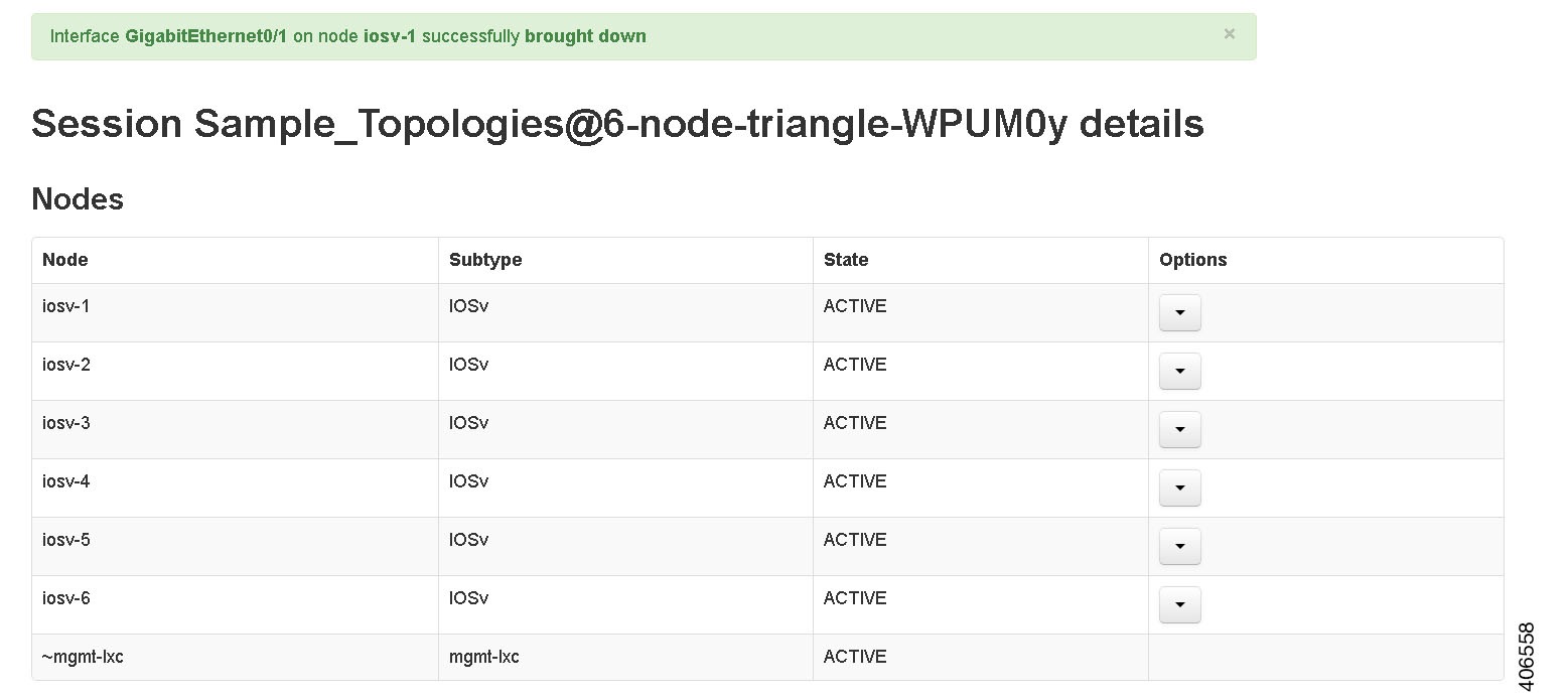 | ||
| Step 6 | To bring up the
interface at a later stage, click
Update admin
state again.
The
Bring up page displayed.
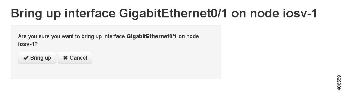 | ||
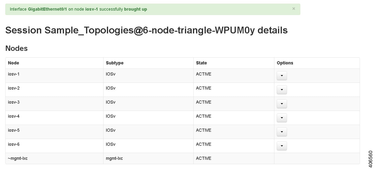
| Step 7 | Click
Bring up to bring up the network interface.
A message
is displayed indicating that the interface has been brought up.
 |
Connect to a Simulation Node Console
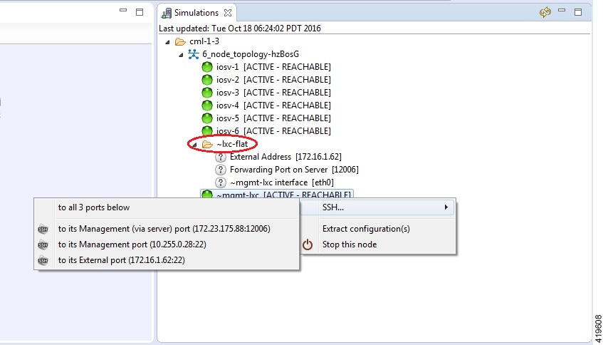
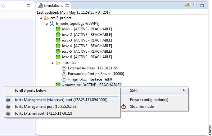
Cisco Modeling Labs provides the capability for you to connect to your nodes via SSH and Telnet. You can start an SSH session, which connects into the node via the LXC, as described in Linux Container (LXC).
This access method makes use of SSH to the LXC and then Telnet from the LXC to the nodes running inside the simulation. This does not use the console port of the nodes and is more reliable and faster to use.
Connect to a Simulation Node Console via SSH
To connect to a simulation node console, complete the following steps.
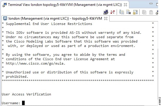
| Step 1 | To connect to a
console for a specific node, right-click the node in the
Simulations view and choose
.
 A new Terminal view opens.
 | ||||
| Step 2 | To disconnect a
terminal from the simulation, click
Disconnect in
the
Terminal view toolbar or click the
Close icon in
the
Terminal view.
|
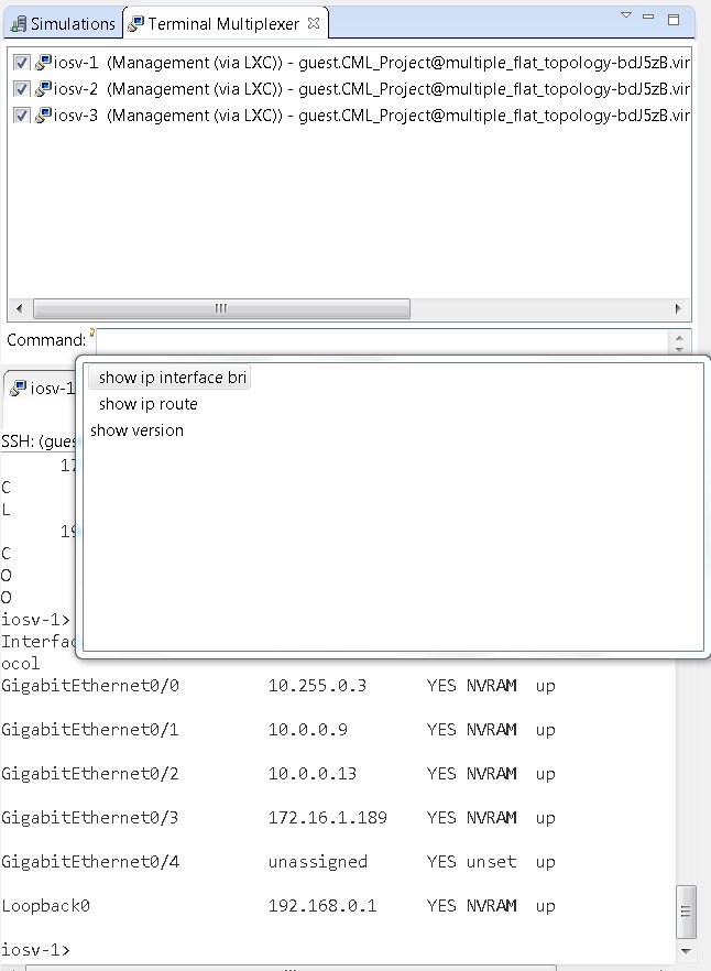
Connect to Multiple Simulation Node Consoles
To connect to all consoles for all nodes in a running simulation, complete the following steps.
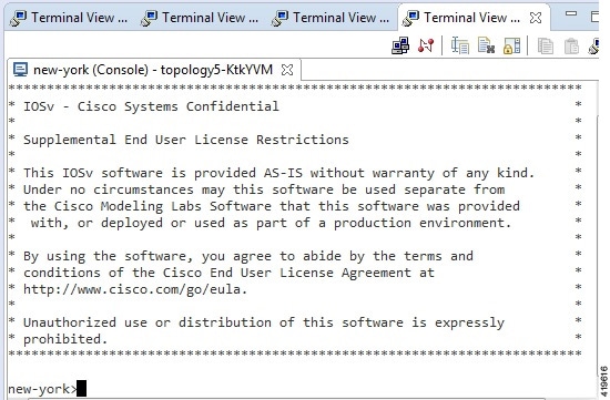
| Step 1 | Right-click the
simulation in the
Simulations view and choose
.
 A new Terminal view opens for all console ports.
 | ||||
| Step 2 | To disconnect a
terminal from the simulation, click
Disconnect in
the
Terminal view toolbar or click the
Close icon in
the
Terminal view.
|
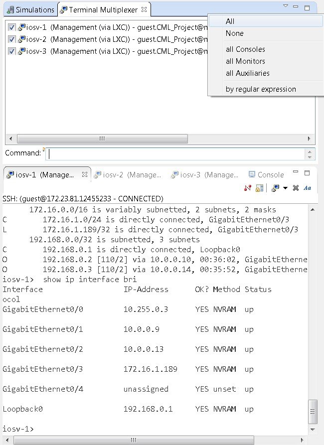
Terminal Multiplexer Functionality
A terminal multiplexer is available for use with the Cisco Modeling Labs client. It permits a number of terminals to be accessed and controlled from a single terminal. Terminals can be detached to run in the background and then reattached later.
The terminal multiplexer is available from .
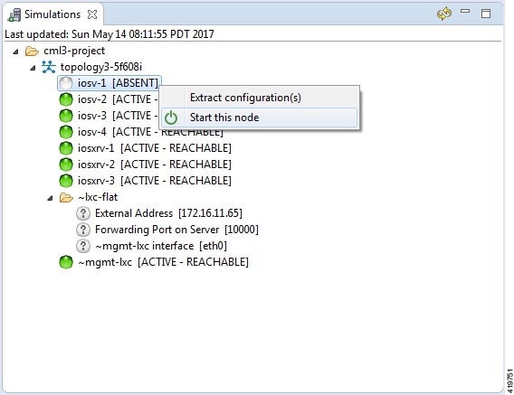
Start a Single Node
To start a single node, complete the following steps.
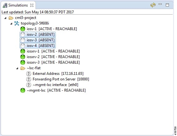
| Step 1 | Right-click a stopped node. When a node is stopped, its status is shown as [ABSENT]. | ||
| Step 2 | Click
Start this node.
  | ||
| Step 3 | Choose one or more
of the following actions:
|
Start a Node in a Running Simulation
In cases where a phased simulation is running, you can later start those nodes not started with the initial simulation. To start a node in a running simulation, complete the following steps.
| Step 1 | In the
Simulations view, right-click the node.
| ||
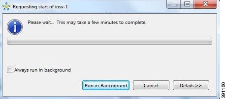
| Step 2 | Click
Start this
node.
The Requesting start dialog box appears.
|
Start Multiple Nodes in a Running Simulation
In cases where a phased simulation is running, you can later start those nodes not started with the initial simulation. To start multiple nodes, complete the following steps.
| Step 1 | In the Simulations view, click the first node in the list to be started. | ||
| Step 2 | Hold down the Shift key and select the remaining nodes. | ||
| Step 3 | Right-click the selected nodes. | ||
| Step 4 | Click
Start nodes.
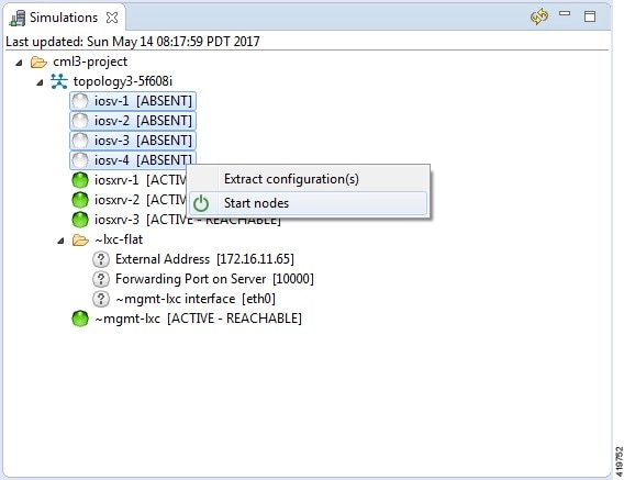
The Requesting start dialog box appears. 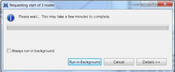
 |
Stop a Simulation
There are several ways to stop a simulation. In addition, you can stop multiple simulations at the same time. These are discussed in the following sections.
Stop a Simulation from the Toolbar
To stop a simulation from the toolbar, complete the following steps.
| Step 1 | In the toolbar,
click the
Stop
Simulations button.
A
Stop
Simulation(s) dialog box appears.
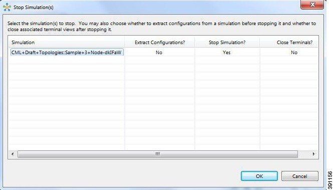 | ||
| Step 2 | In the Simulation column, click once to highlight the simulation to stop. | ||
| Step 3 | (Optional) To
save the configurations, click the adjacent setting in the
Extract
Configurations? column until the prompt changes to
Yes.
| ||
| Step 4 | (Optional) To
close the internal terminals associated with the simulation, click the adjacent
setting in the
Close
Terminals? column until the prompt changes to
Yes.
| ||
| Step 5 | To stop the simulation, click the adjacent setting in the Stop Simulation? column until the prompt changes to Yes. | ||
| Step 6 | Click
OK to stop the
simulation, or click
Cancel to leave
the simulation running.
On OS X, you update the values for Extract Configurations?, Stop Simulation?, and Close Terminals? in the columns directly. You do not need to select the name of the simulation. |
Stop a Simulation from the Simulations View
To stop a simulation, complete the following steps.
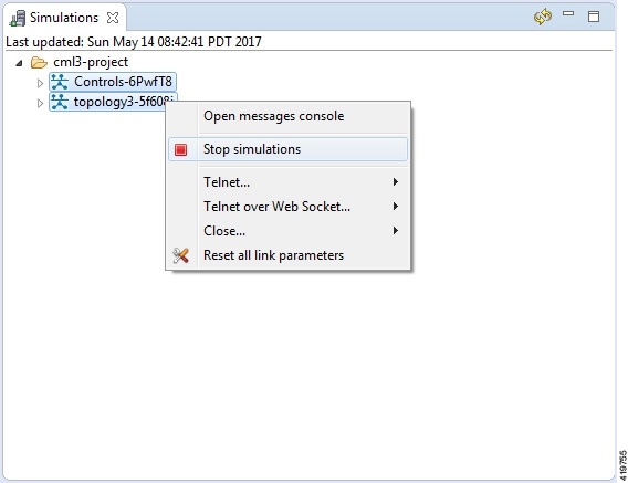
| Step 1 | In the
Simulations view, right-click the simulation name and
select
Stop
Simulation.
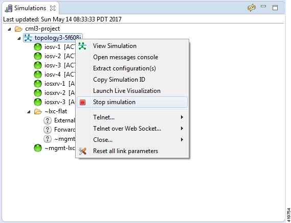 The Stop Simulation Confirmation dialog box appears. 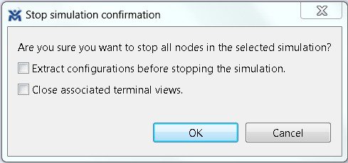
| ||
| Step 2 | Click
OK to stop the
simulation.
Once
selected, all nodes in the simulation start shutting down. It may take a few
minutes for the simulation to shut down completely and to disappear from the
Simulations view.
|
Stop Multiple Simulations from the Simulations View
To stop multiple simulations, complete the following steps.
| Step 1 | In the Simulations view, click the first simulation in the list to stop. | ||
| Step 2 | Hold down the Shift key and select the remaining simulations. | ||
| Step 3 | Right-click the
selected simulations and select
Stop
Simulations.
 The Stop Simulations Confirmation dialog box appears. 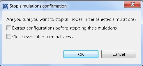
| ||
| Step 4 | Click
OK to stop the
simulations.
Once
selected, all nodes in the simulations start shutting down. It may take a few
minutes for the simulations to shut down completely and to disappear from the
Simulations view.
|
Stop a Single Node
To stop a single node in a simulation, complete the following steps.
| Step 1 | In the
Simulations view, right-click the node to stop and
select
Stop this Node.
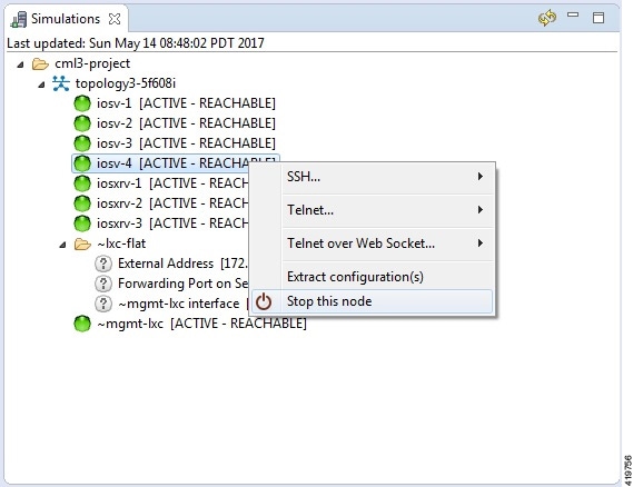 The Are you sure? dialog box appears. | ||
| Step 2 | Click
OK to stop the
node. Alternatively, click
Cancel to abandon
the operation and return to the simulation.
|
Stop Multiple Nodes
To stop multiple nodes in a running simulation, complete the following steps.
| Step 1 | In the Simulations view, click the first node in the list to stop. | ||
| Step 2 | Hold down the Shift key and select the remaining nodes. | ||
| Step 3 | Right-click the selected nodes. | ||
| Step 4 | Click
Stop Nodes.
 The Are you sure? dialog box appears. | ||
| Step 5 | Click
OK to stop the
nodes. Alternatively, click
Cancel to
abandon the operation and return to the simulation.
 |
Modify a Node Configuration in the Simulation
Modify a Node Configuration in the Simulation via SSH
To modify a node configuration in a running simulation via SSH, complete the following steps.
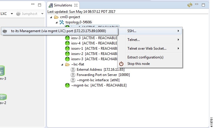
| Step 1 | Right-click the
node in the
Simulations view and choose
SSH > to its
Management (via LXC) port.
 A new Terminal view opens.
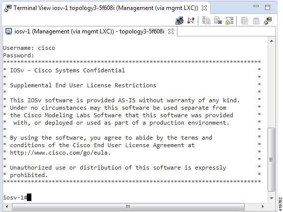 | ||
| Step 2 | If no banner or router prompt is visible, press Enter. You are now working with the operating system running on the node, for example, Cisco IOSv virtual software. | ||
| Step 3 | Use the
operating system commands to view or modify the node configuration.
|
Modify a Node Configuration in the Simulation via Telnet
To modify a node configuration in a running simulation via Telnet, complete the following steps.
| Step 1 | Right-click the
node in the
Simulations view and choose
Telnet > to
its Console port.
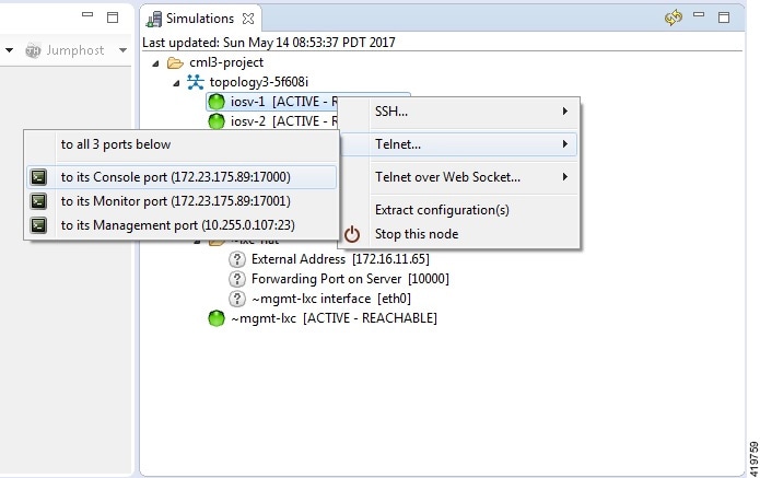 A new Terminal view opens.
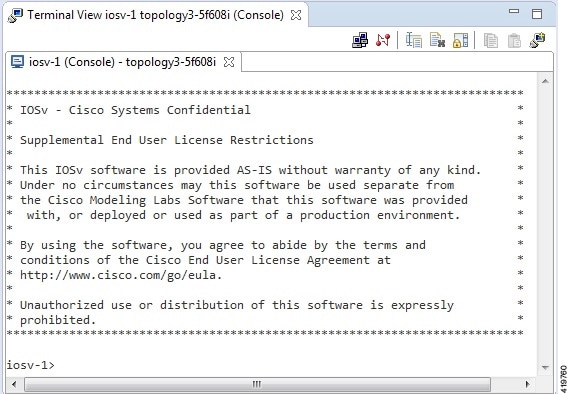 | ||
| Step 2 | If no banner or router prompt is visible, press Enter. You are now working with the operating system running on the node, for example, Cisco IOSv virtual software. | ||
| Step 3 | Use the
operating system commands to view or modify the node configuration.
|
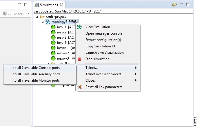
Modify Multiple Node Configurations in the Simulation
To modify multiple node configurations in a running simulation, complete the following steps.
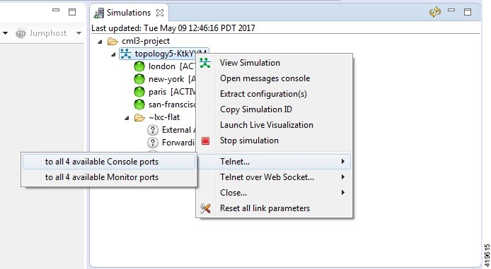
| Step 1 | Right-click the
topology in the
Simulations view and choose
Telnet > to
all <number> available Console ports.
 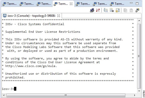 | ||
| Step 2 | If no banner or router prompt is visible, press Enter. You are now working with the operating system running on the node, for example, Cisco IOSv virtual software. | ||
| Step 3 | Use the
operating system commands to view or modify the node configuration.
|
Extract and Save Modified Configurations
To extract and save modified configurations, complete the following steps.
| Step 1 | In the
Simulations view, right-click the topology name,
making sure not to click the node name, and select
Extract
Configurations.
 | ||
| Step 2 | Ensure that all
external Telnet connections to the simulation are closed before proceeding.
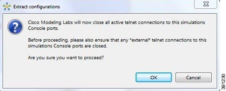 | ||
| Step 3 | Click
OK.
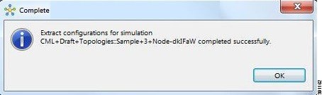
The Extracting Configurations dialog box appears indication that the extraction is in process. When the extraction is complete, a message is displayed.
| ||
| Step 4 | Click OK. |
Partial Configuration Extraction
During a configuration extraction, if the process encounters issues or fails for a particular node, the problem node is identified and reported.
The extraction process then continues for all other nodes in the simulation and returns collected configurations to you.
Linux Server Snapshot Support
When a Linux server is present in a running simulation, you can use the User Workspace Management interface to take a snapshot of the disk content of the server. This newly created user-specific disk image can be used in other simulated sessions.
To take a snapshot of the server's disk contents, complete the following steps.| Step 1 | Log in to the
User Workspace Management interface.
| ||
| Step 2 | On the
Overview page, under
Sessions,
select the applicable running simulation.
 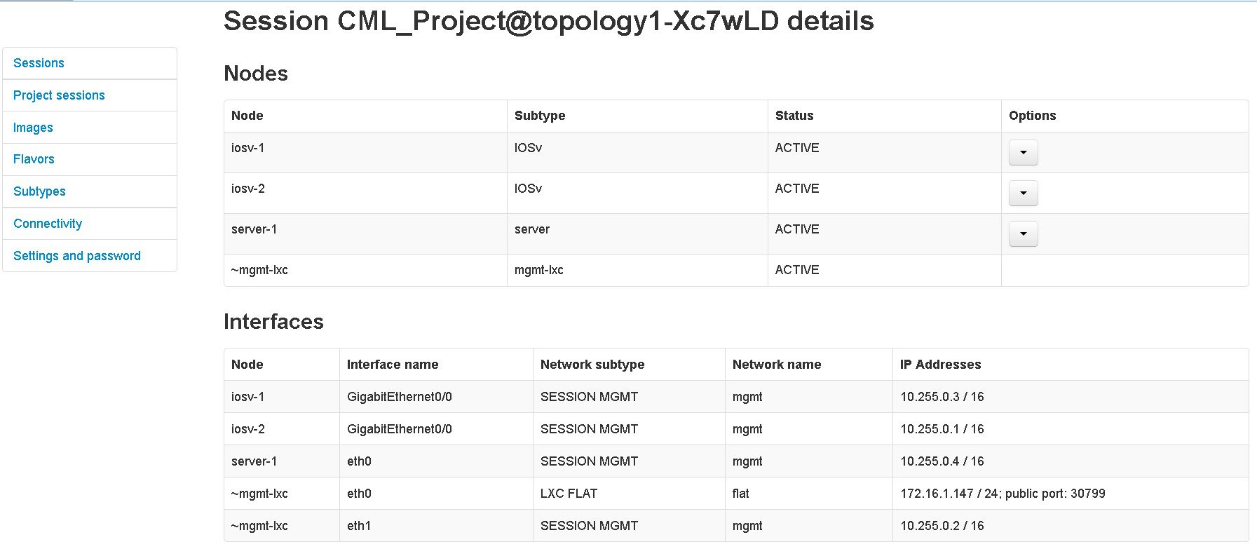 | ||
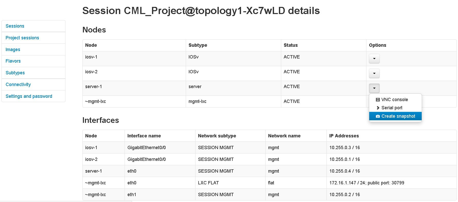
| Step 3 | Select the
applicable Linux server, and from the
Options
drop-down menu, click
Create
snapshot.
 Project details for the newly created snapshot are displayed. 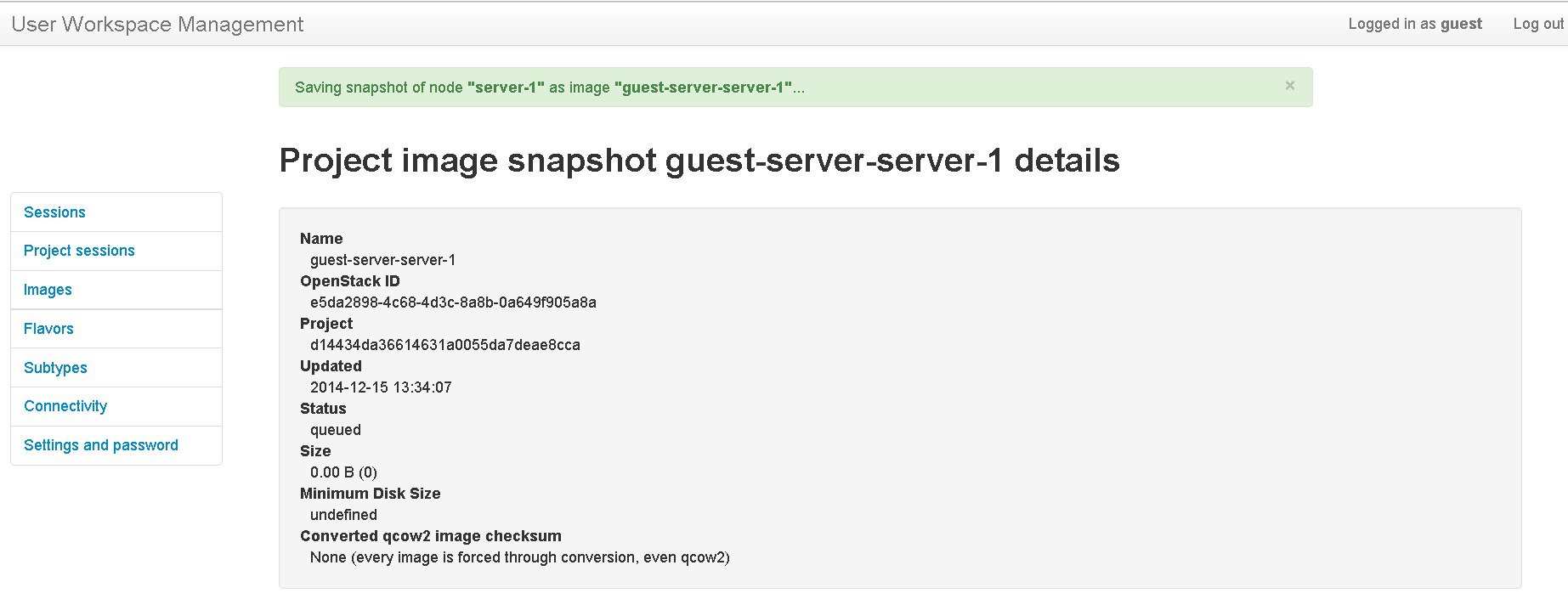 |
Reuse the Image Snapshot
To reuse the image snapshot, complete the following steps.
| Step 1 | Create a new topology or open an existing topology. |
| Step 2 | On the canvas, add a node to the topology. |
| Step 3 | Select the node on the canvas. The sample topology opens in the Topology Editor canvas. |
| Step 4 | In the view, click Browse beside the VM Image field. The Select VM Image dialog box appears. |
| Step 5 | Select the
applicable image snapshot and click
OK.
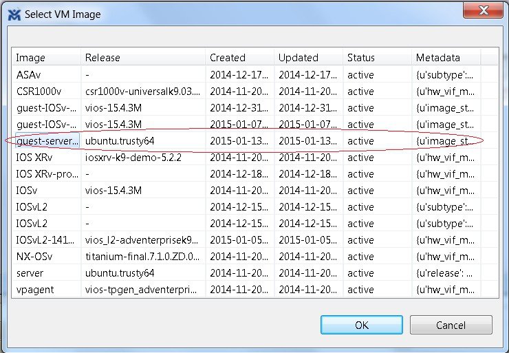 Details for the image snapshot are visible in the VM Image field under view. 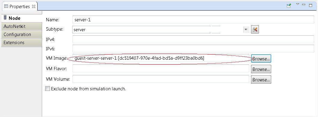 |
Latency, Jitter and Packet Loss Control Options
The availability of link-level parameters allows users to investigate and understand the impact on services of transmission characteristics encountered in the physical world. With a running simulation, you are able to select links between the nodes in the simulation and set latency, jitter and packet-loss values on those links. This enables you to create links that have properties seen in the physical world such as transatlantic or transcontinental latencies or packet-loss.
The link parameters can be applied on any link, except for those connected to a FLAT or SNAT external connector. The values set by the user are applied bi-directionally, meaning that setting a latency value of 100ms results in 100ms from node A to node B and 100ms from node B to node A for the return path. That is 200ms in total. The same is true for packet-loss. Ten packets sent from node A on a link with 10% packet-loss results in 9 packets being received on node B. The packet loss will also be applied on the return path meaning that another packet may be lost between node B and node A.
-
In the Cisco Modeling Labs Client client. Figure 65. Setting Link Parameters in the Cisco Modeling Labs Client 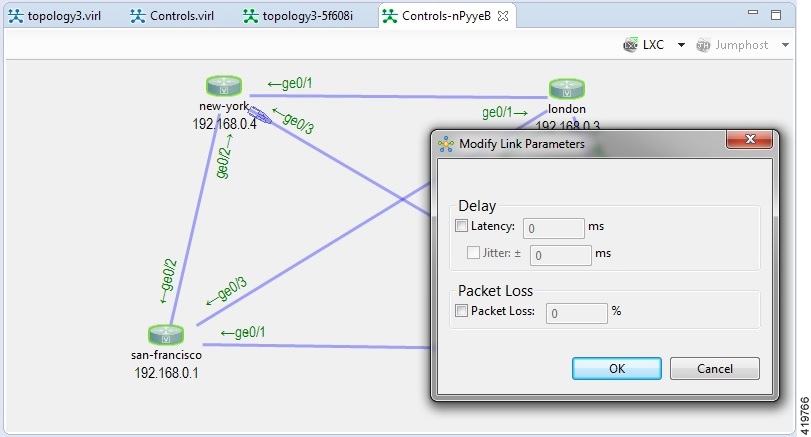
-
In the User Workspace Management interface. Figure 66. Setting Link Parameters in the User Workspace Management Interface 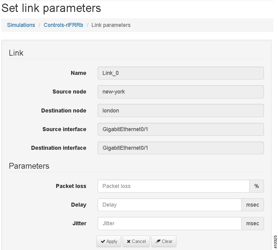
-
In the Live Visualization view of the running simulation.
Figure 67. Setting Link Parameters in the Live Visualization View 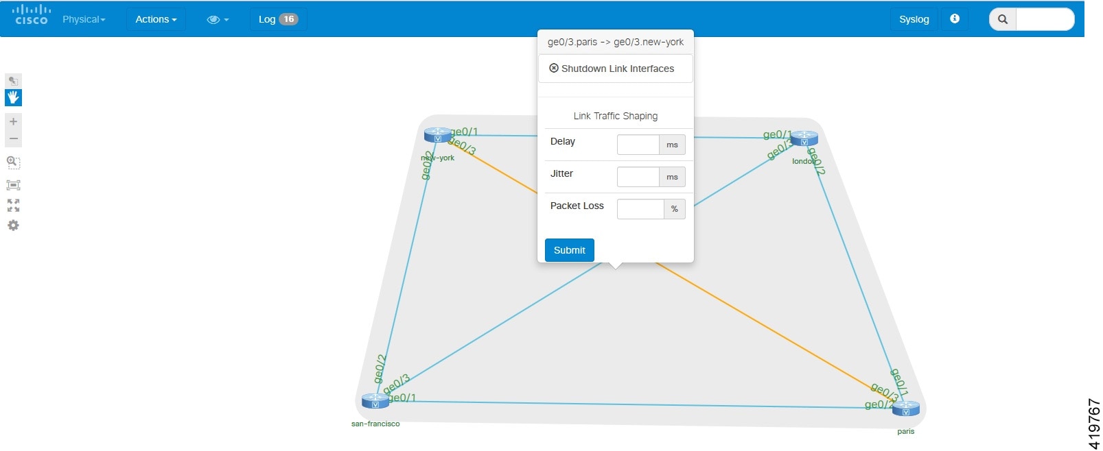
Coordinated Packet Capture
When inspecting traffic passing across the network, it can be valuable to be monitor more than one interface at a time and also to start the packet capture at the same time. Coordinated packet capture capabilities is provided in the User Workspace Management interface. When a simulation is up and running, you can select one or more interfaces and mark them for traffic capture. You are then able to specify the traffic capture parameters including the packets to match (using PCAP filter syntax), the time to run the capture, or the number of packets to capture. You can either start the capture on the marked interfaces immediately, or do so at a later point in time.
Once complete, you can either download the per-interface .PCAP files or output to a .ZIP file containing the .PCAP files for each interface.
Using the Coordinated Packet Capture Feature
To use the coordinated packet capture feature, complete the following steps.
| Step 1 | From the Cisco Modeling Labs client toolbar, click Launch a Simulation to start the simulation. | ||
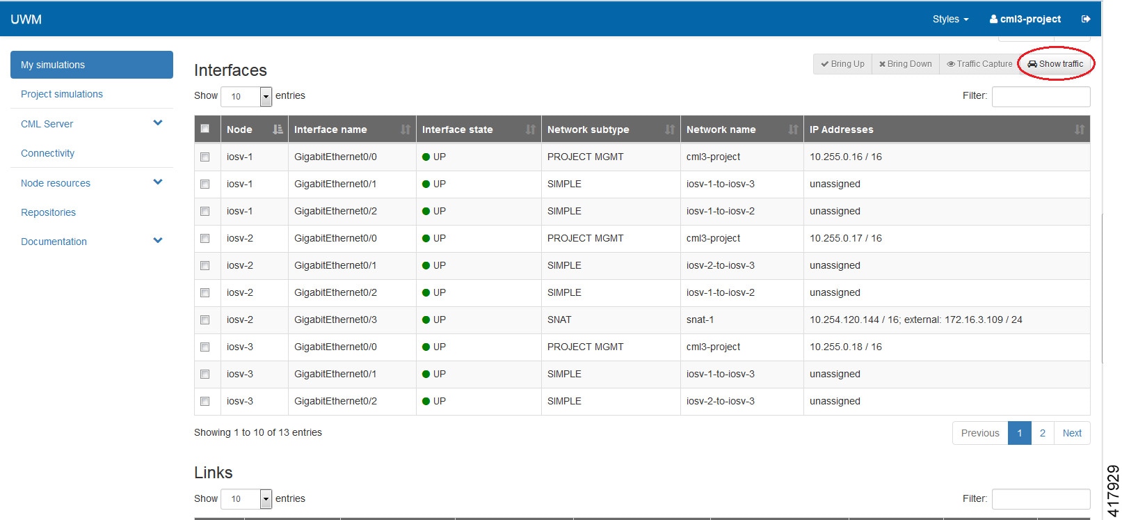
| Step 2 | Log in to the User Workspace Management interface and click the My simulations option as shown. | ||
| Step 3 | Under the
Interfaces
panel, select the applicable interfaces.
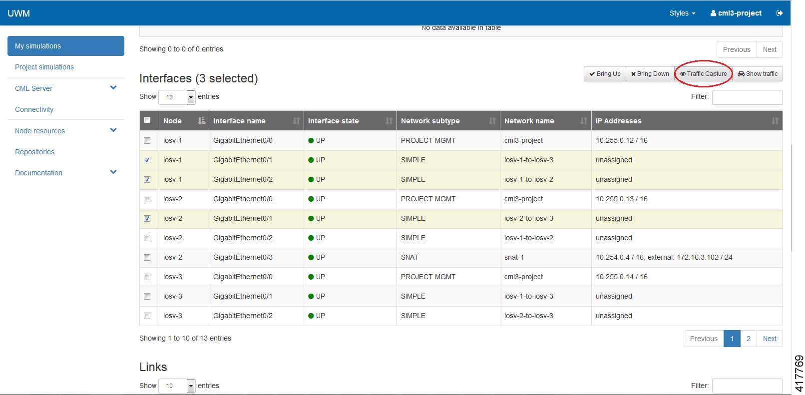
| ||
| Step 4 | Once all
interfaces are selected, click the
Traffic
Capture option.
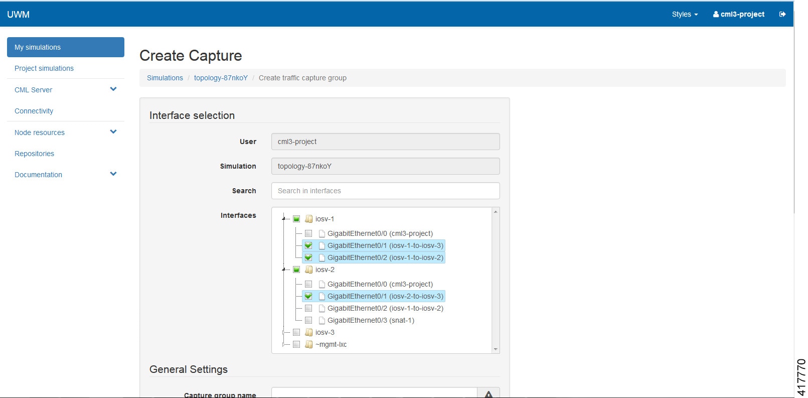
The
Create
Capture page is displayed.
| ||
| Step 5 | Under
General
Settings, provide a name for your capture grouping.
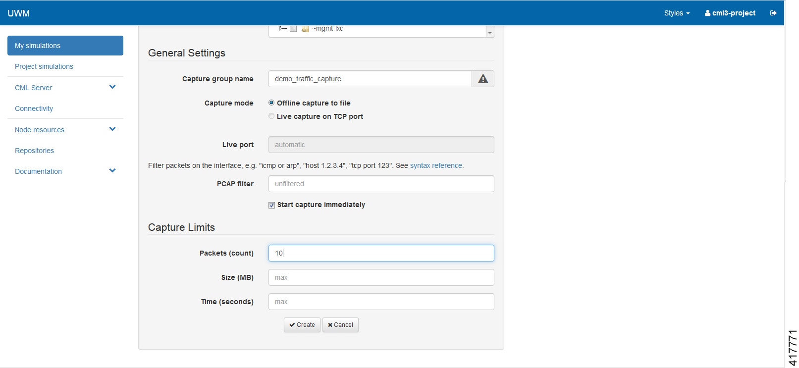 | ||
| Step 6 | Specify any packet capture limits for packets (count), size (MB), and time (seconds) in the Capture Limits panel. | ||
| Step 7 | Click
Create.
A
confirmation message is displayed indicating that the capture group was
successfully created.
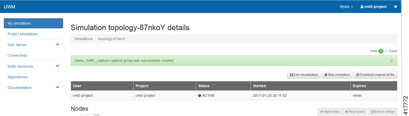 | ||
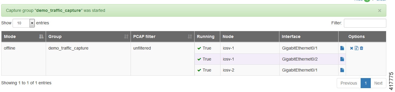
| Step 8 | Under the
Traffic
Captures panel, all entries are listed, with the running status
False, as
shown.
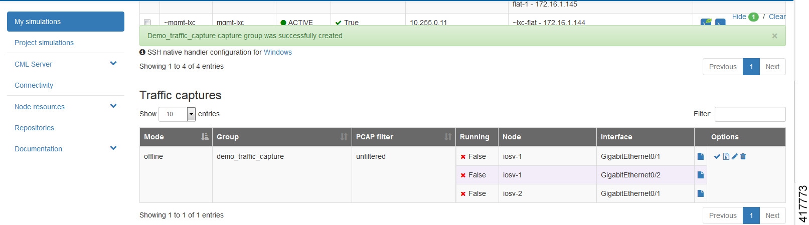 | ||
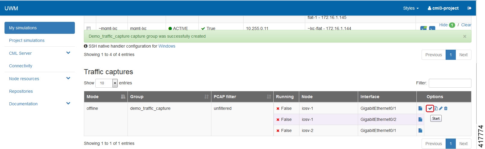
| Step 9 | Click the
Start icon to start the capture.
| ||
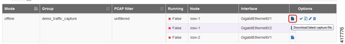
| Step 10 | You have the
option to download each .PCAP file individually or all of them together in a
.ZIP file.
 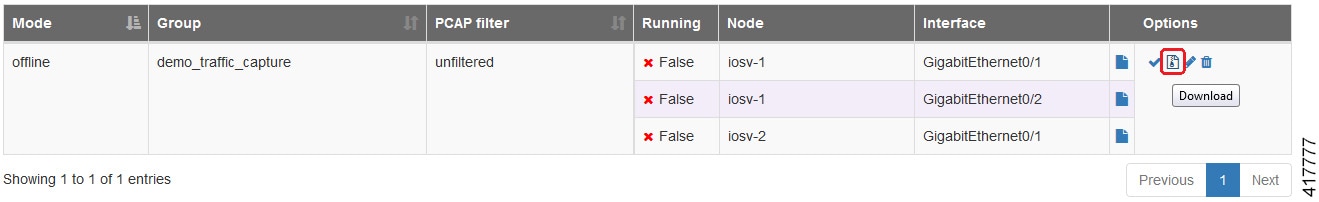 | ||
| Step 11 | For the ZIP file option, you can see the list of packet capture
files, as shown.
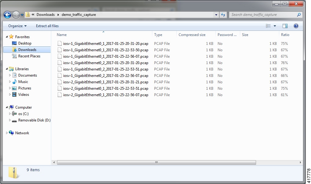 You can view the packet capture details as required. |
Real-time Traffic Visualization
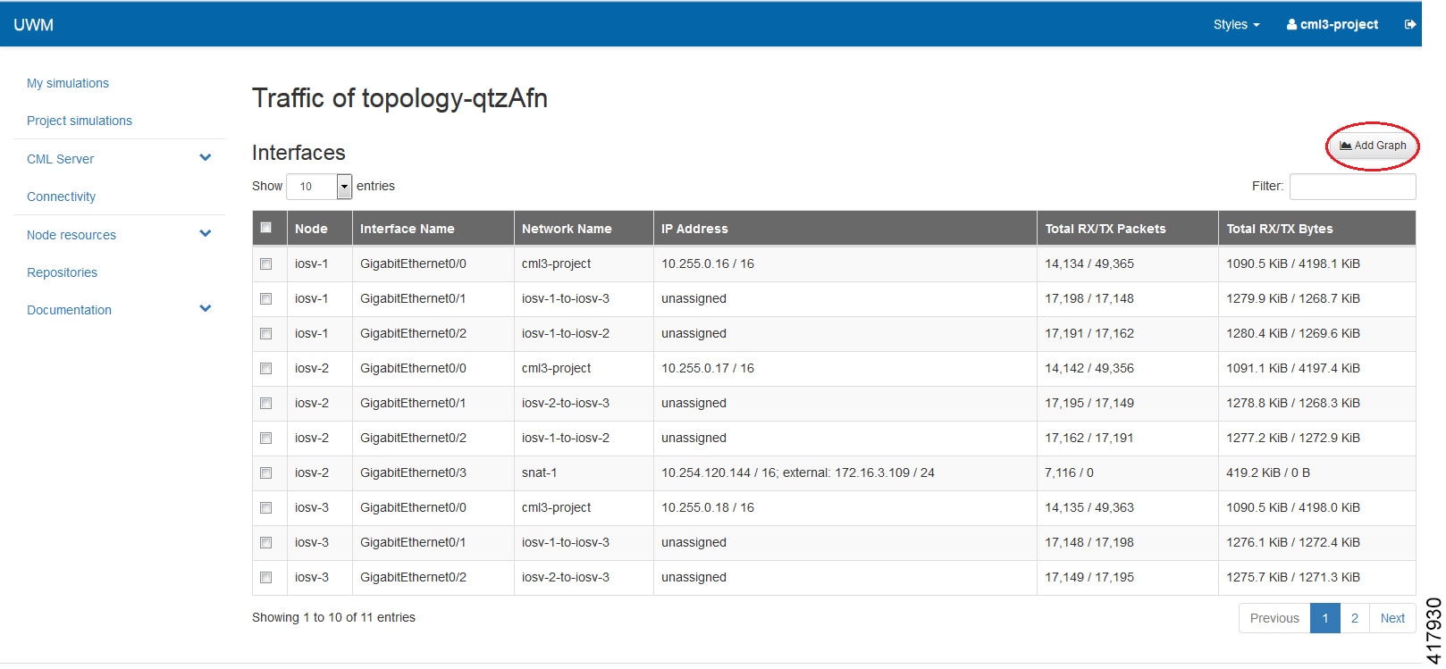
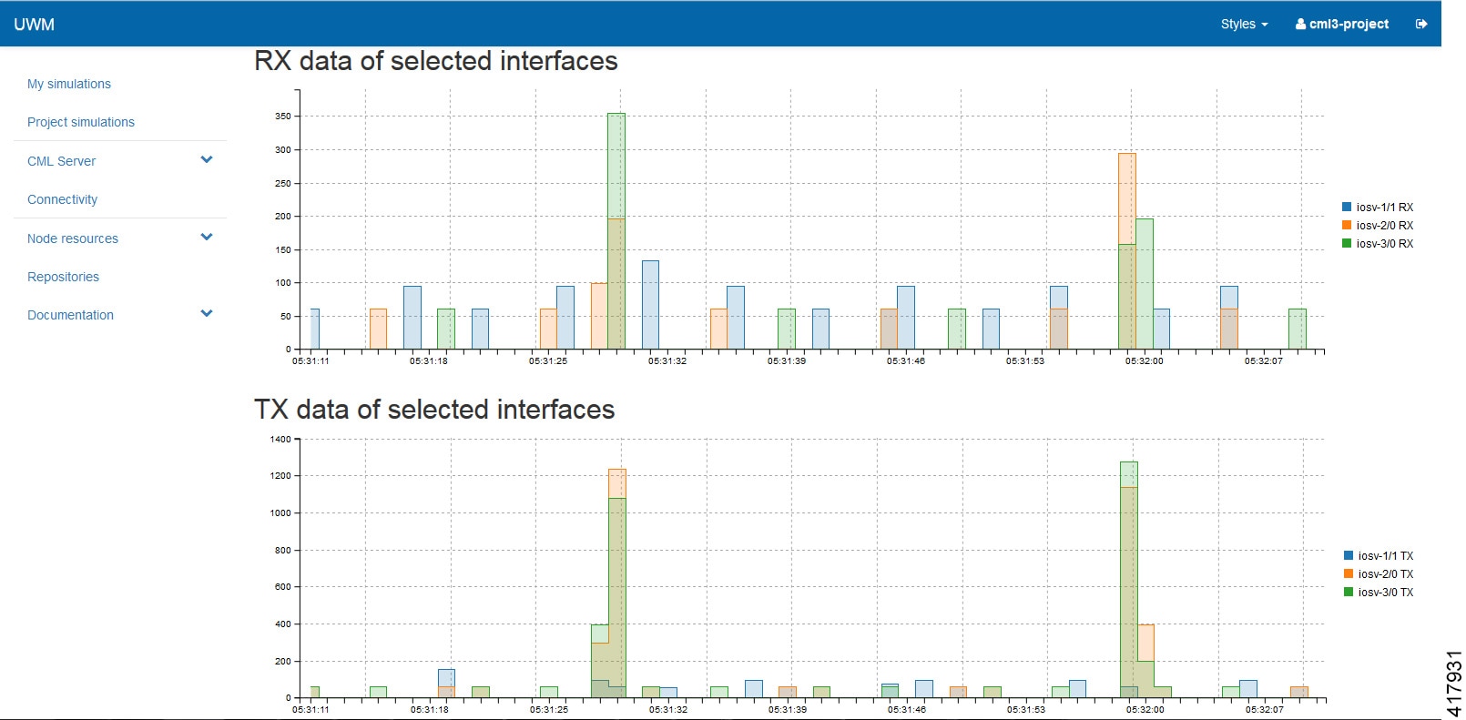
Note | In cases where the RX/TX packet and byte counters report loading and do not populate with values for a running simulation, clearing your browser cache will resolve this issue. |
 Feedback