Design a
Topology
Design a Topology Overview
The design phase is the initial step in creating a network topology. During the design phase, you will perform the tasks described in the following sections.
Topology Nodes and Connections
The topology you design consists of nodes and connection functions. See Navigating Within the Cisco Modeling Labs Client for additional information about how to select and edit nodes and connection functions.
Topology Nodes
|
Node Name |
Node Type |
|---|---|
|
Cisco IOSv |
Router node. Runs a Cisco IOS operating system. |
|
Cisco IOSvL2 |
Router node. Runs a Cisco IOS Layer 2 operating system. |
|
Server |
Server node. Runs a Linux operating system. |
|
Cisco IOS XRv |
Router node. Runs a Cisco IOS XR operating system. |
|
Cisco IOS XRv 9000 |
Router node. Runs a Cisco IOS XR 9000 operating system. (Available separately.) |
|
Cisco CSR1000v |
Router node. Runs a Cisco CSR 1000 operating system. (Available separately.) |
|
Cisco ASAv |
Router node. Runs a Cisco ASAv operating system. |
|
Cisco NX-OSv 9000 |
Router node. Runs a Cisco Nx-OS 9000 operating system. |
A node subtype is a virtual machine that runs on top of OpenStack, which itself is running in a Linux virtual machine that is running on top of VMware software. Because the node is virtual, specific hardware is not emulated. For example, there are no power supplies, no fans, no ASICs, and no physical interfaces. For all router nodes, the interface type is a Gigabit Ethernet network interface. A server node has an Ethernet network interface.
You can choose an image and image flavor for each node type. See the User Workspace Management chapter in the Cisco Modeling Labs Corporate Edition System Administrator Installation Guide, Release 1.3 for information on how to access the VM Image and the VM Flavor choices. In most cases, you need not select an image and flavor. By default, the node subtype is associated with an image and flavor that runs with the topology.
|
VM Image Name |
Used For |
|---|---|
|
server |
Server node |
|
CSR1000v |
Cisco CSR1000 node |
|
IOSv |
Cisco IOS node |
|
IOSvL2 |
Cisco IOS Layer 2 node |
|
IOS XRv |
Cisco IOS XR node |
|
IOS XRv 9000 |
Cisco IOS XR 9000 node |
|
AVAv |
Cisco AVAv node |
|
Nx-OSv 9000 |
Cisco NX-OSv 9000 node |
|
VM Flavor Name |
Used For |
|---|---|
|
m1_tiny |
Linux server |
|
m1_small |
Linux server |
|
m1_medium |
Linux server |
|
m1_large |
Linux server |
|
m1_xlarge |
Linux server |
|
server |
Linux server |
|
CSR1000v |
Cisco CSR 1000 node |
|
IOS XRv |
Cisco IOS XR node |
|
IOS XRv 9000 |
Cisco IOS XR 9000 node |
|
IOSv |
Cisco IOS node |
|
IOSvL2 |
Cisco IOS Layer 2 node |
|
AVAv |
Cisco AVA node |
|
NX-OSv 9000 |
Cisco NX-OS 9000 node |
Each Linux flavor provides a different amount of memory and CPU allocated to the server.
Connection Functions
Cisco Modeling Labs provides the connection functions shown in the following table.
| Connection Type | Description |
|---|---|
| Connection | Creates a connection between two interfaces. Interfaces are created in the node to support a connection. Any unused interfaces present are automatically assigned. All the interfaces in router nodes are represented as Gigabit Ethernet interfaces. Multiple parallel connections are supported. |
| External Router | Creates an
external router connection point.
When the external router is used in conjunction with a Layer 2 External (Flat) network and IOSv instances, AutoNetkit is able to configure an L2TPv3 tunnel to connect simulations to remote devices in a transparent manner. |
| Layer 3 External (SNAT) | Creates a Layer 3 external connection point using static network address translation (SNAT). This external connection point allows connections outside of Cisco Modeling Labs to connect to the topology. |
| Layer 2 External (Flat) | Creates a Layer 2 external connection point using FLAT. This external connection point allows connections outside of Cisco Modeling Labs to connect to the topology. |
Create a Topology
A topology project folder must exist.
There are several methods for creating a topology. These are discussed in the following sections.
Method 1: Create a Topology from the Menu Bar
Method 2: Create a Topology from the Projects View
Method 3: Create a Topology from the Toolbar
What to Do Next
Place the nodes.
Place the Nodes on the Canvas
What to Do Next
Create connections and interfaces.
Create Connections and Interfaces
Nodes must be in place on the canvas of the Topology Editor.
| Step 1 | Click Connection in the Tools view. | ||||
| Step 2 | Click the first node. | ||||
| Step 3 | Click the next node to create the connection.
| ||||
| Step 4 | Repeat Step 2 and Step 3 until all the connections are in place.
|
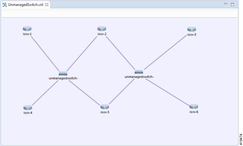
Use Unmanaged Switches
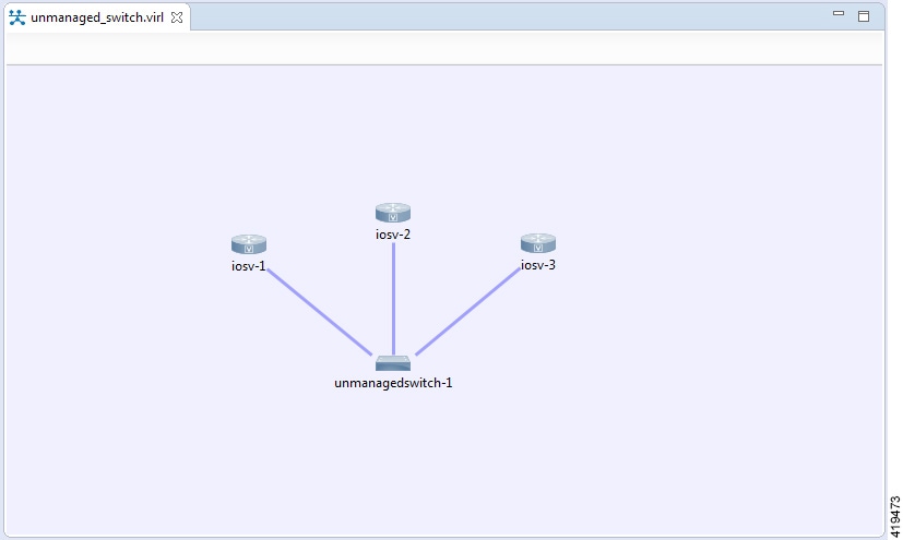
A topology file with the extension .virl must exist. Router nodes or server nodes are placed on the canvas. Optionally, connections may exist between nodes.
| Step 1 | In the Nodes view, click Unmanaged Switch. |
| Step 2 | Click the area on the canvas where you want the unmanaged switch to appear. |
| Step 3 | In the Tool view, click Connect. |
| Step 4 | On the canvas,
click the unmanaged switch node then click an end node. A connection appears.
Continue
clicking unmanaged switch-node combinations until all connections are made.
 |
The Cisco IOSvL2 Switch Image
 Note | All Cisco IOSvL2 switch images in a topology are counted against the licensed node limit. |
A Cisco IOSvL2 switch image provides sixteen Gigabit Ethernet interfaces, reserving interface Gi0/0 for OOB management. It can be configured manually or using AutoNetkit.
Any routers set up to connect to the Cisco IOSvL2 switch will be in switchport access mode. By default, all routers are placed in VLAN 2. You can specify which VLAN to place a port in by setting a VLAN attribute on the router interface. See Assign VLANs for details on how to do this.
Switch to switch connections configured using AutoNetkit are by default set to operate as an 802.1q trunk.
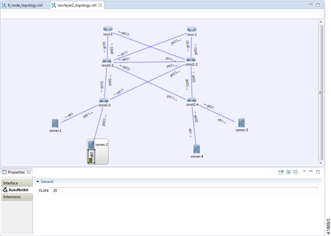
Use the Cisco IOSvL2 Switch Image
| Step 1 | In the Nodes view, click IOSvL2. |
| Step 2 | Click the canvas at each point where you want to place an IOSvL2 node. You can also drag the nodes on the canvas to position them. |
| Step 3 | Add additional node types as required. |
| Step 4 | Use the Connect tool to create connections between the nodes. |
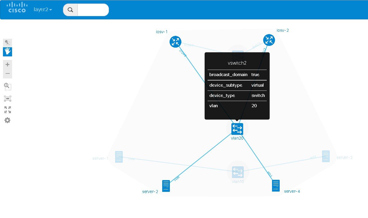
| Step 5 | To specify which VLAN to place a port in, select the interface for the host or router by double-clicking the applicable node. |
| Step 6 | Under
, enter a value for the
VLAN
field, as shown.
 |
| Step 7 | From the
toolbar, click
Build Initial
Configurations to generate a configuration for the topology using
AutoNetkit. When prompted to open AutoNetkit visualization, click
Yes.
AutoNetkit visualization for the topology opens in a browser
window.
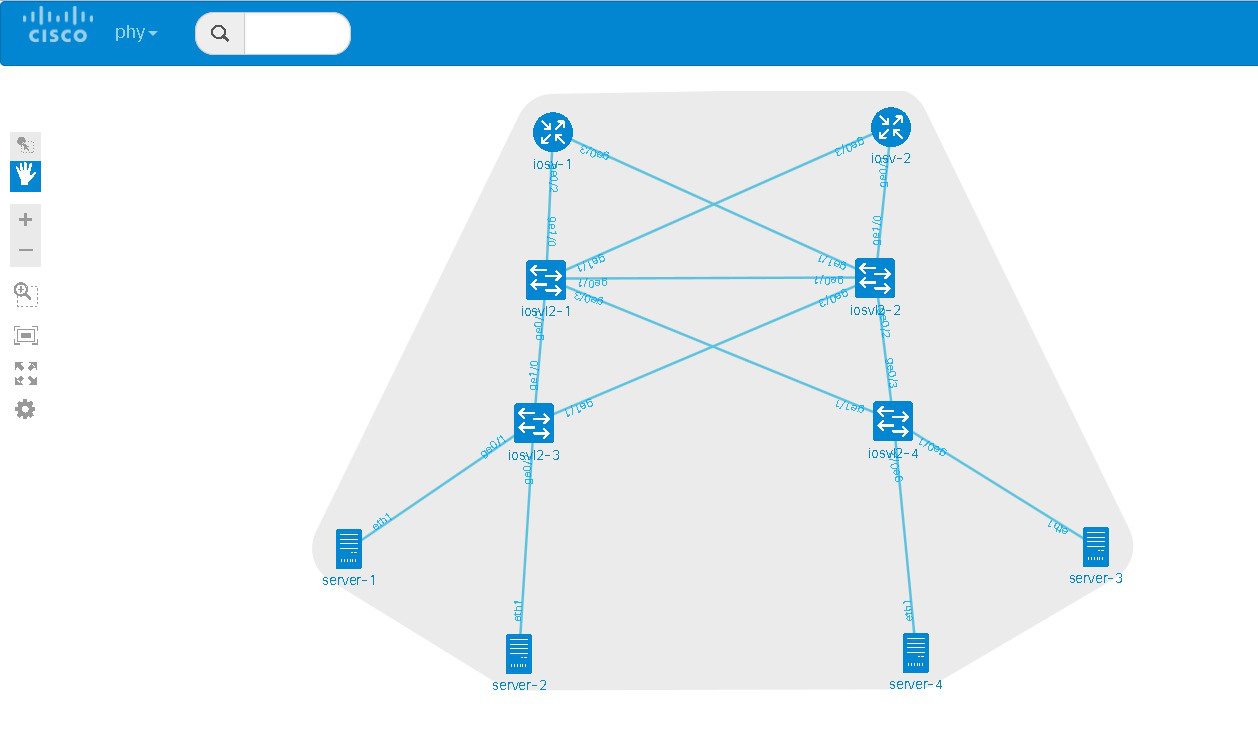 |
| Step 8 | To view all
broadcast domains that are enabled, select
layer2_conn from the
phy
drop-down list. For example, hovering over server-2 in this example shows the
routers and servers that are in the same VLAN. All other devices are greyed
out.
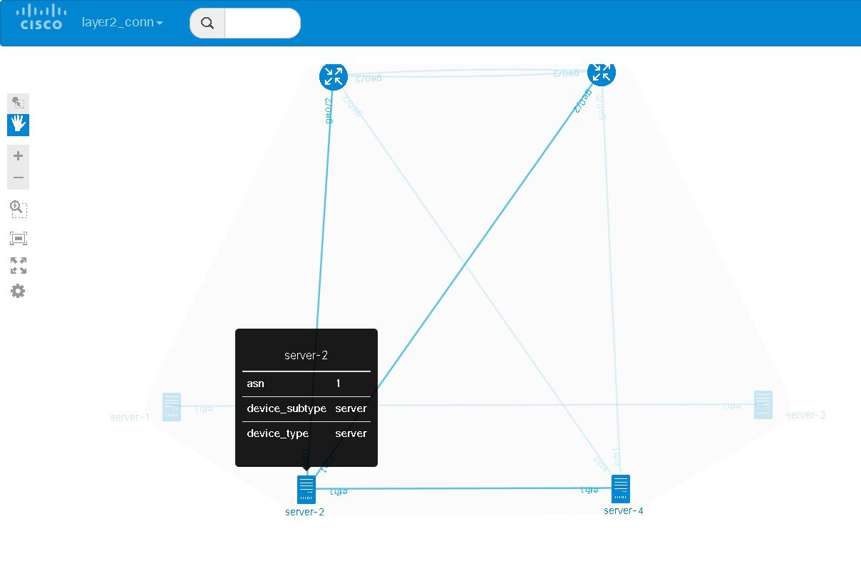  |
| Step 9 | In the Cisco
Modeling Labs client, click
Launch
Simulation to start the simulation.
The
simulation starts and is visible in the
Simulations view.
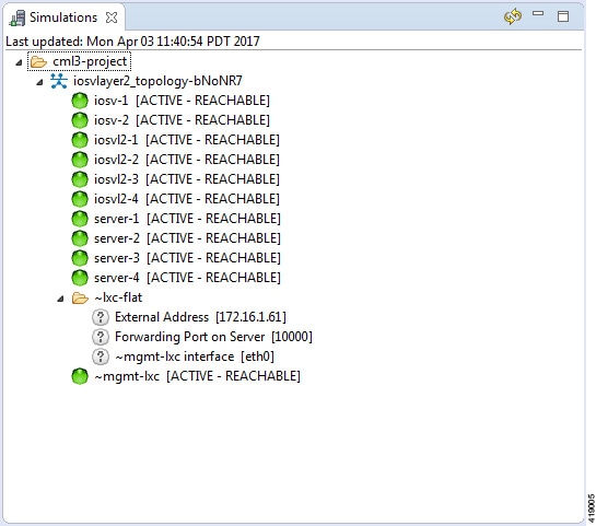 |
Docker Container Support
Cisco Modeling Labs provides the ability to integrate Docker images into Cisco Modeling Labs topologies.
Users are able to select docker images from public repositories (such as hub.docker.com) or private repositories. Once downloaded to your Cisco Modeling Labs server, you are able to design a network topology that will include your docker image.
In Cisco Modeling Labs, docker functionality is placed inside another virtual machine, CoreOS; which acts as a host for running docker instances. This is done for two reasons, for security and to constrain and restrict how many instances you have running by putting in place memory controls around the resources utilizations of the various docker instances.
Note | You must install the CoreOS virtual machine image. This is available for installation from the Cisco Modeling Labs FileExchange. Please contact cml-info@cisco.com if you require access. |
You can have many docker instances but you need to be careful with the amount of memory that docker instances require. Understand that CoreOS is running docker services as well as the docker instances themselves. There is a limit of 22 docker instances running at any one time. This limit is set by the number of interfaces that the KVM supports.
Basic configuration information (interface and routing details) are provided by AutoNetkit using the build initial configurations function. As part of the simulation launch, the CoreOS virtual machine is spun up and the docker instance started within it. The docker instance will appear as if it were directly connected to the other nodes within your simulation. The neighboring devices are unaware of the presence of the CoreOS VM that is hosting the docker instances. Each link that is created in the topology design results in an external tap interface being created on the CoreOS instance. The CoreOS VM is configured to run with 2Gb RAM and 2vCPUs. If the amount of memory is insufficient, it can be adjusted using the Node Resources/Flavors function in the User Workspace Management interface.
There are thousands of docker images available on public repositories. However, not all images will run on Cisco Modeling Labs (or any other docker deployment), so care must be taken when selecting the image.
Using Integrated Docker Containers in Cisco Modeling Labs Topologies
To use integrated docker containers in your topologies, complete the following steps.
| Step 1 | Download the docker image to the Cisco Modeling Labs server. |
| Step 2 | In the User
Workspace Management interface, the list of available subtypes is accessed
using
as shown.
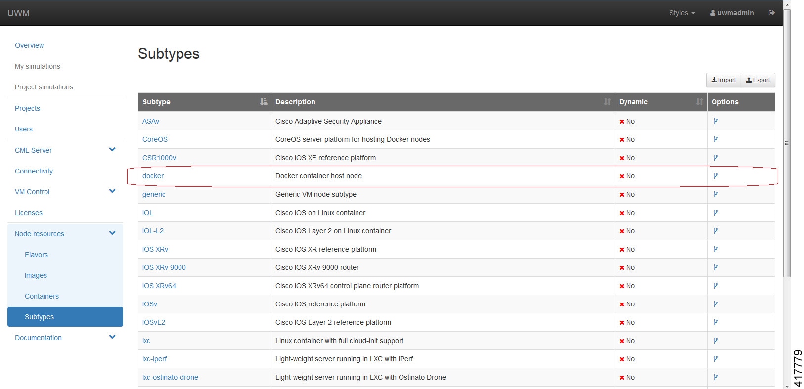
For each docker type that is added, you need to create a subtype using the Specialize option to clone the template provided. 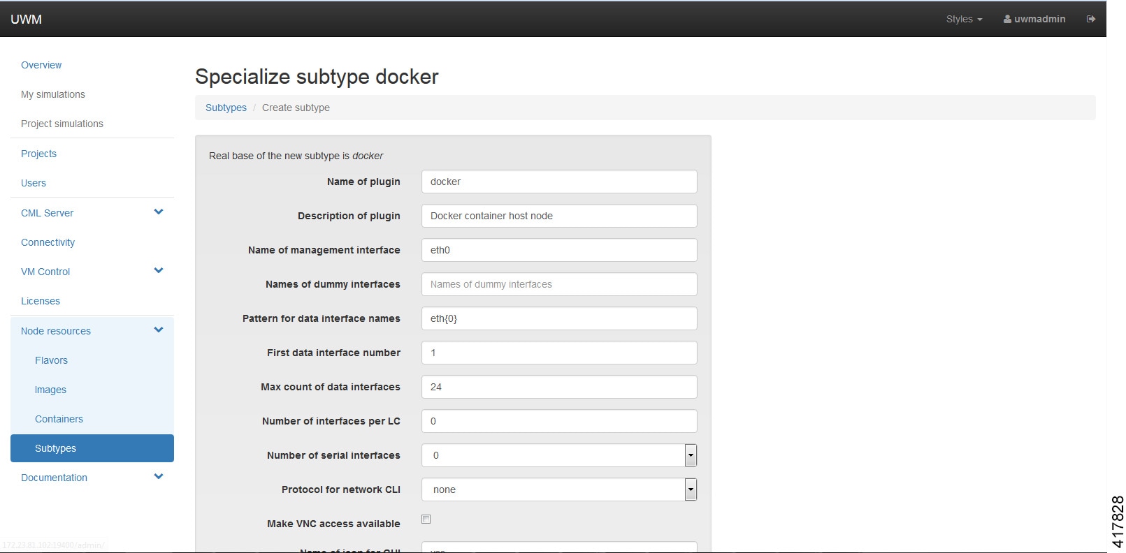 Click Create. The newly created subtype is displayed in the Subtypes list. |
| Step 3 | Under
, click
Add.
Browse the docker repository and search for the applicable image, for example, coreos/apache. Select the option and note down the applicable Docker Pull Command, eg. docker pull coreos/apache. |
| Step 4 | In the
Create
Docker Image page, select the newly created docker subtype from the
drop-down list.
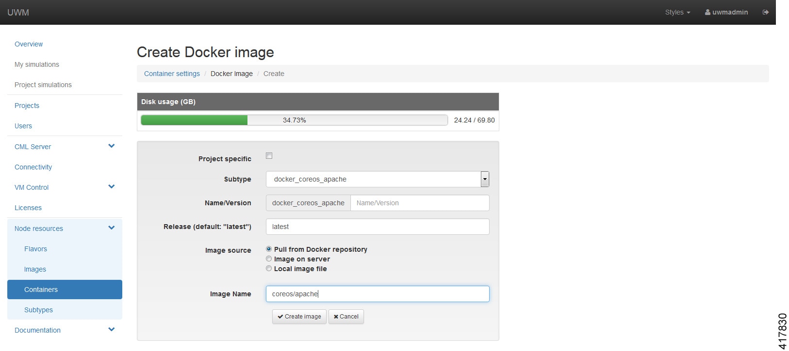 In the Image Name field, enter the docker pull command noted earlier. Click Create Image. The content is now downloaded. The new docker image is displayed in the Docker Images list. |
| Step 5 | To add the docker image for use in Cisco modeling Labs topologies, open the Cisco modeling Labs client. |
| Step 6 | Choose and click Fetch from Server. The newly created docker image is displayed in the Node Subtypes list. Additionally, the docker image icon is also available from the Topology Palette for use in topology design. |
 Feedback