Mitigate Network Congestion


Note

Functionality described within this section is only available as part of the Advanced RTM license package.


Cisco Crosswork can proactively monitor network bandwidth utilization and mitigate congestion to help alleviate the difficult task of tracking and reacting to traffic utilization changes that go above a specified threshold by using one of two tools: Local Congestion Mitigation and Bandwidth Optimization.

Bandwidth Optimization (BWOpt) provides closed-loop traffic engineering by automatically rerouting intent-based traffic dynamically throughout the network in response to congestion. For more information, see Use BWOpt to Optimize the Network

Local Congestion Mitigation (LCM) searches for congestion on a configurable cadence (as opposed to a triggered event) and provides localized mitigation recommendations within surrounding interfaces (local interface-level optimization). You are able to visually preview these recommendations on your network before you decide whether to commit the Tactical Traffic Engineering (TTE) SR policy deployment. LCM performs the collection of TTE SR policy and interface counters via SNMP and does not require the use of SR-TM. For more information, see Use LCM to Mitigate Congestion Locally


Note

LCM allows for a wider applicability of the solution in various network topologies such as that involving multiple IGP areas due to its simpler path computation and limitation to specific network elements. Focusing on the problem locally eliminates the need for simulating edge-to-edge traffic flows in the network through a full traffic matrix.


Use LCM to Mitigate Congestion Locally

Local Congestion Mitigation (LCM) checks the capacity locally, in and around the congested area, at an interface level. LCM computes the shortest paths for one or more tactical policies to divert the minimal amount of traffic on a congested interface to alternate paths with sufficient bandwidth. It attempts to keep as much of the traffic on the original IGP path. If the user approves, LCM performs the mitigation through the deployment of Tactical Traffic Engineering (TTE) SR policies. LCM will not modify paths of existing deployments of SR policies to mitigate congestion.

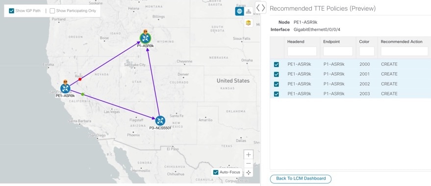
TTE tunnel recommendations are listed in the LCM Operational Dashboard. From the dashboard, you can visually preview the TTE SR policy recommendations before deployment. TTE SR policy deployment to resolve congestion is not automated. You must approve and commit LCM recommended actions. LCM also recommends removal of previous TTE SR policies (instantiated by LCM) if they are no longer needed.

LCM Important Notes

Consider the following information when using LCM:

  • LCM evaluates network utilization on a regular, configurable cadence of 10 minutes or more. The cadence is typically set to be greater than or equal to the SNMP traffic polling interval.

  • LCM leverages ECMP across parallel TTE SR policies and assumes roughly equal splitting of traffic. The degree to which actual ECMP splitting adheres to this assumption depends on the presence of large elephant flows and the level traffic aggregation.

  • Traffic that can be optimized must not be carried on existing SR-TE policies.

Platform Requirements

The following is a non-exhaustive list of high-level requirements for proper LCM operation:

Congestion Evaluation:

  • LCM requires traffic statistics from the following:

    • SNMP interface traffic measurements

    • SNMP headend SR-TE policy traffic measurements

  • Strict SID labels should be configured for SR.

Congestion Mitigation:

  • Headend device should support Equal Cost Multi-Path (ECMP) across multiple parallel SR-TE policies

  • Headend device must support PCE-initiated SR-TE policies with autoroute steering

    Devices should be configued with force-sr-iinclude to enable traffic steering into SR-TE policies with autoroute. For example:

    segment-routing traffic-eng pcc profile <id> autoroute force-sr-include

LCM Calculation Workflow

This example walks you from congestion detection to the calculations LCM performs prior to recommending tactical tunnel deployment.

Figure 1. LCM Configuration Workflow Example
LCM Configuration Workflow Example

Procedure


Step 1

LCM first analyzes the Optimization Engine Model (a realtime topology and traffic representation of the physical network) on a regular cadence.

Step 2

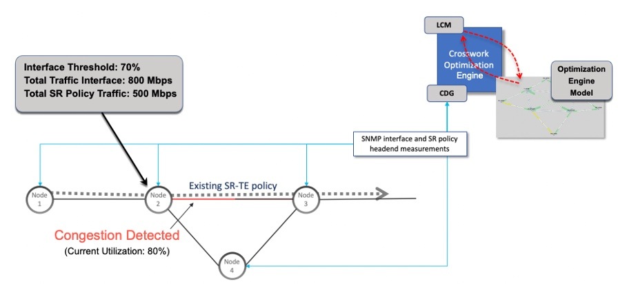
In this example, after a congestion check interval, LCM detects congestion when Node 2 utilization goes above the 70% utilization threshold.

Step 3

LCM estimates how much traffic is eligible to divert.

LCM only diverts traffic that is not on an existing SR policy (for example: unlabeled, IGP routed, or carried via FlexAlgo-0 SIDs). SR-TE policy traffic is not included in LCM calculation as eligible traffic and will continue to travel over the original programmed path.

Eligible traffic is computed by taking the interface traffic stats that account for all traffic on the interface and subtracting the sum of traffic stats for all SR-TE policies that flow over the interface.

Total interface traffic – SR policy traffic = Eligible traffic that can be optimized

This process must account for any ECMP splitting of SR policies to ensure the proper accounting of SR policy traffic. In this example, the total traffic on congested Node 2 is 800 Mbps. The total traffic of all SR policies routed over Node 2 is 500 Mbps.

The total traffic that LCM can divert in this example is 300 Mbps: 800 Mbps – 500 Mbps = 300 Mbps

Step 4

LCM calculates the amount that must be sent over alternate paths by subtracting the threshold equivalent traffic from the total traffic on the interface. In this example, the amount to be diverted is 100Mbps:

800 Mbps – 700 Mbps (70% threshold) = 100 Mbps

LCM must route 100 Mbps of 300 Mbps (eligible traffic) to another path.

Step 5

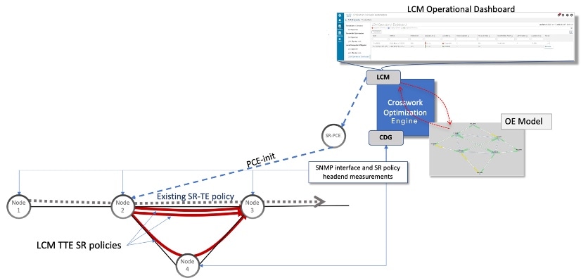
LCM determines how many TTE SR policies are needed and their paths. The ratio of how much LCM eligible traffic can stay on the shortest path to the amount that must be detoured, will determine the number of TTE SR policies that are needed on the shortest versus alternate paths, respectively.

In this example, LCM needs to divert 1/3 of the total eligible traffic (100Mbps out of 300Mbps) away from congested link. Assuming a perfect ECMP, LCM estimates 3x tactical SR-TE policies in total to create this traffic split: 1 tactical SR-TE policy will take the diversion path and 2 tactical SR-TE Policies will take the original path. There is sufficient capacity in the path between Node 2 and Node 4. Therefore, LCM recommends 3 TTE SR policies (each expected to route approximately 100Mbps ) to be deployed from Node 2 to Node 3 via SR-PCE:

  • 2 TTE SR policies to take a direct path to Node 3 (200 Mbps)

  • 1 TTE SR policy takes hop via Node 4 (100 Mbps)

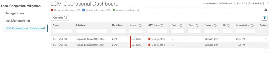
These recommendations will be listed in the LCM Operational Dashboard.

LCM Recommendation Example

Step 6

Assuming you deploy these TTE SR policies, LCM continues to monitor the deployed TTE policies and will recommend modifications or deletions as needed in the LCM Operational Dashboard. TTE SR policy removal recommendations will occur if the mitigated interface would not be congested if these policies were removed (minus a hold margin). This helps to avoid unnecessary TTE SR policy churn throughout the LCM operation.


Mitigate Congestion on Local Interfaces Example

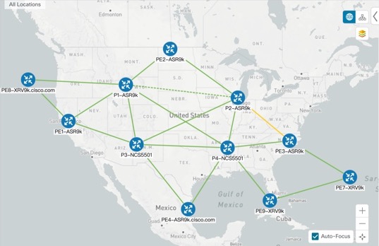
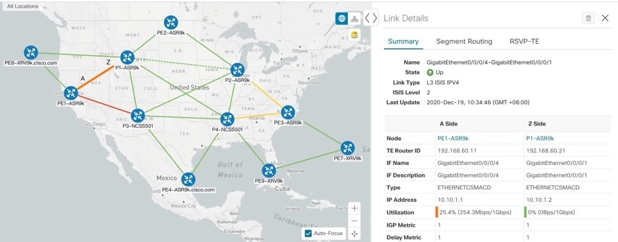
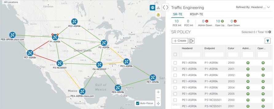
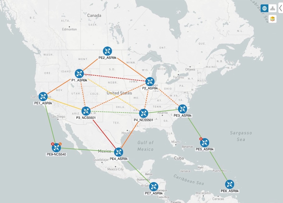
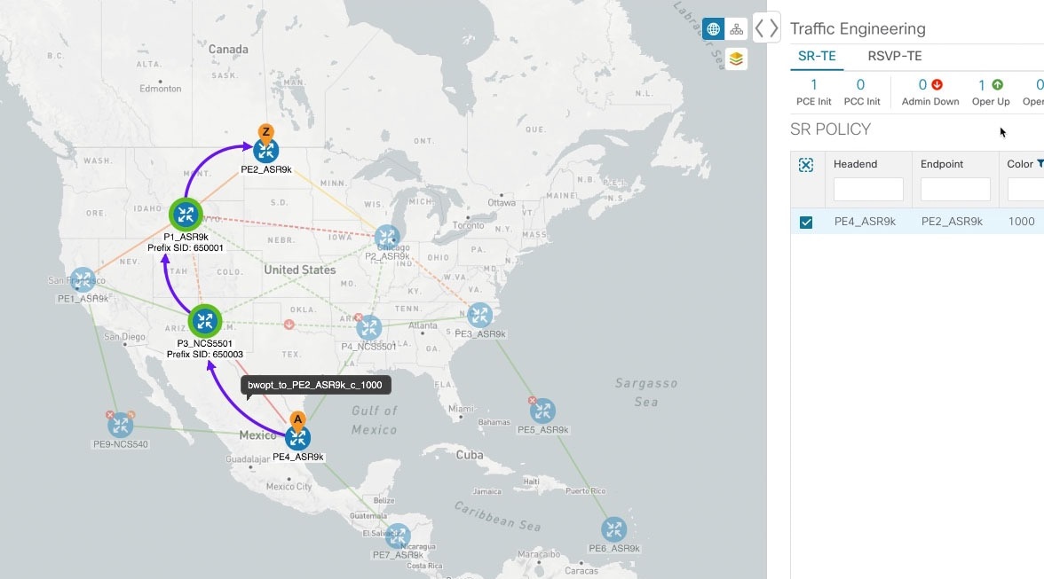
In this example, we will enable LCM and observe the congestion mitigation recommendations to deploy TTE SR polices when utilization surpasses a defined threshold. We will preview the recommended TTE SR policies before committing them to mitigate the congestion. The following image shows the initial topology before congestion occurs.

LCM - Initial Topology

Procedure


Step 1

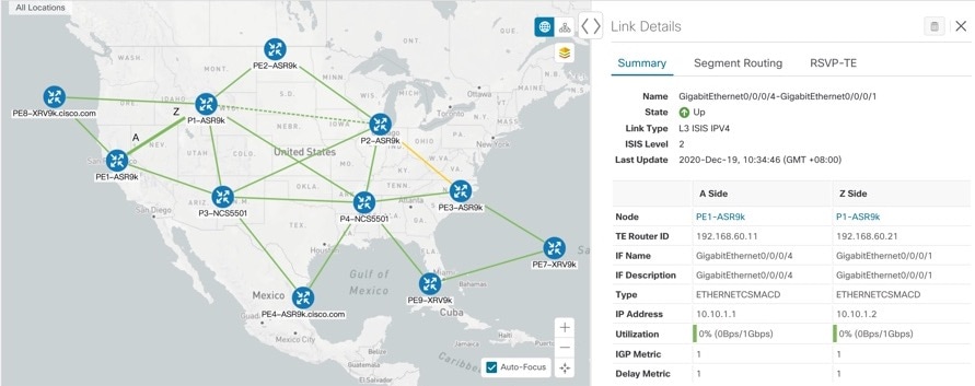
View initial topology and utilization prior to LCM configuration.
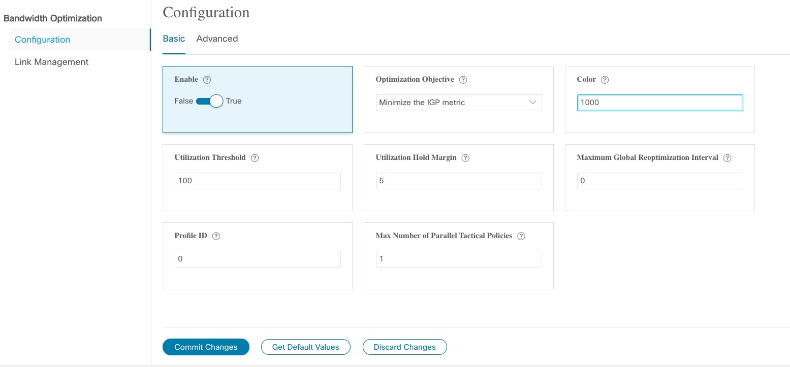
  1. Click on the link between PE1-ASR9k and P1-ASR9k to view link details. Note that there is currently no congestion (0% utlization).

    Initial Link Utilization
Step 2

Enable LCM and configure the global utilization threshold.
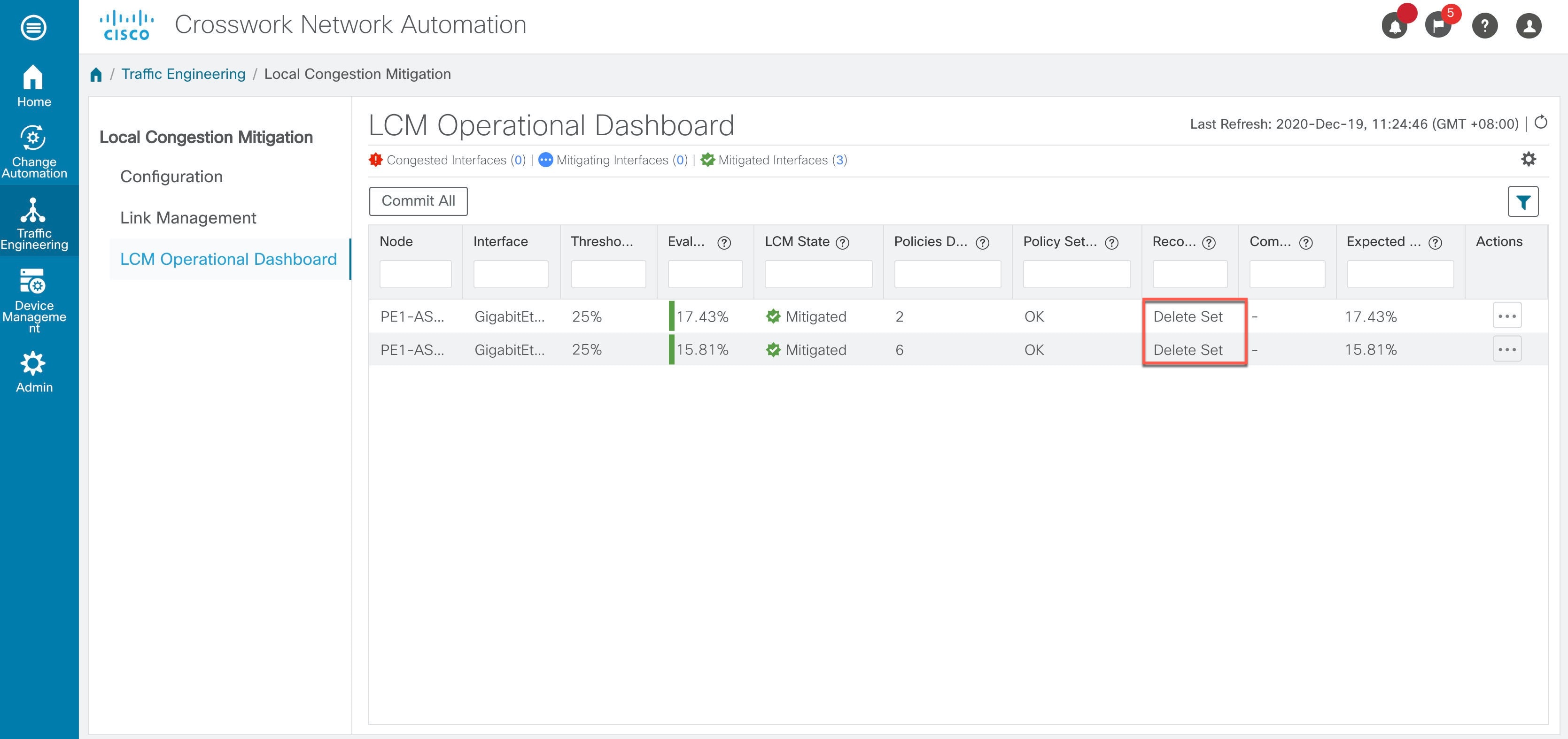
  1. From the main menu, choose Traffic Engineering > Local Congestion Mitigation > Configuration. In this case, the threshold is set at 25%.

    LCM Configuration Window

    If you want to set separate threshold for individual interfaces, toggle the Include All Interfaces to False.

  2. (optional) Define any specific thresholds for individual links by uploading a CSV file (Traffic Engineering > Local Congestion Mitigation>Link Management).

    Note 

    A sample CSV template is available for download.

Step 3

View TTE SR policy recommendations in the LCM Dashboard.
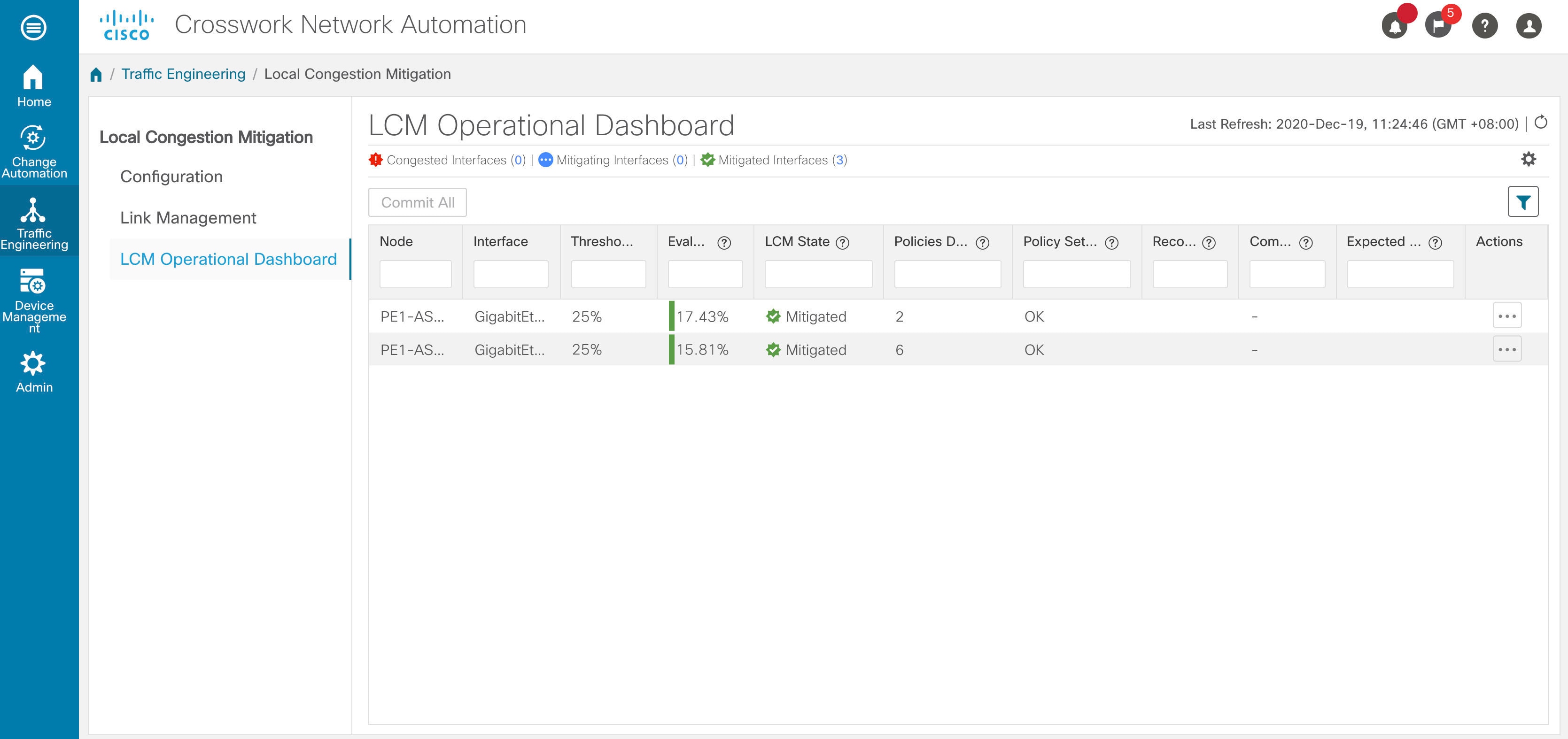
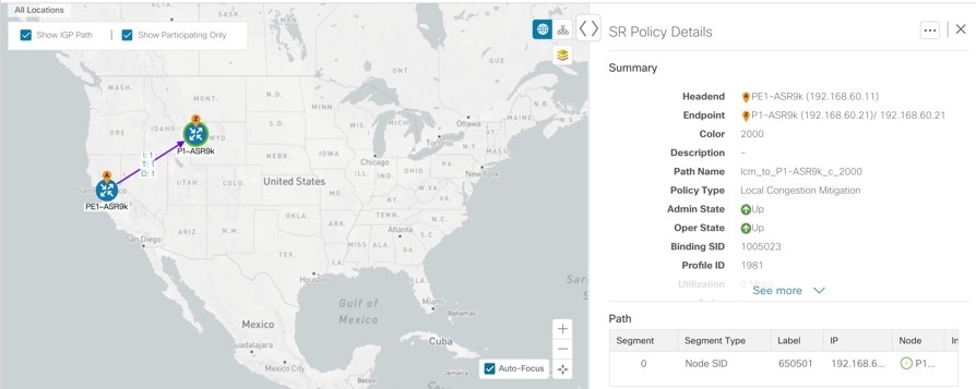
  1. After some time, congestion occurs surpassing the configured LCM threshold. Note that the link is Orange, indicating higher utilization.

    Topology Congestion
  2. Click Show Events icon to view the new event. You can also monitor this window to view LCM events as they occur. You should see events for LCM recommendations, commit actions, and any exceptions.

  3. Open the LCM Operational Dashboard (Traffic Engineering > Local Congestion Mitigation> LCM Operational Dashboard).

    The dashboard shows that the utilization has surpassed 25%. In the Recommended Action colum, there is a recommendation to deploy 2 TTE policy solution sets to address the congestion on each interface. The Expected Util column shows the expected utilization of each of the interface if the recommended action is committed.

    LCM Operational Dashboard Recommendations
  4. To preview the TTE deployment of each TTE policy solution set, click Edit icon and choose Preview. The window displays the node, interface, and the recommended action for each TTE policy. The following figure shows the recommended TTE policies for the interface GigabitEthernet0/0/0/4.

    From the Preview window, you can select the individual TTE policies, and view different aspects and information as you would normally do in the topology map.

    Preview TTE Policies
  5. If you are satisfied with the LCM recommendations, click Commit All. The LCM Status column changes to Mitigating.

    Note 

    All LCM recommendations must be committed in order to mitigate congestion and produce the expected utilization as shown in the LCM Dashboard. The mitigating solution is based on all LCM recommendation being committed because of dependencies between solution sets.

    LCM Operational Dashboard
Step 4

Validate TTE SR policy deployments.

  1. Click Show Events icon to open the Events window and note which LCM events are listed in this window. LCM - Events Wiindow

  2. Return to the LCM Dashboard to see that the LCM state changes to Mitigated for all TTE policy solution sets.

    Note that the LCM state change will take up to 2 times longer than the the SNMP cadence.

    LCM Operational Dashboard - Mitigated
  3. Confirm the TTE policy deployment by viewing the topology map and the SR Policy table (Traffic Engineering > Traffic Engineering > SR-TE tab).

    SR-TE Policy Deployment
    Tip 

    To help narrow the search for the SR-TE policies that were just deployed, click Settings icon from the SR Policy table and click the checkbox to include Policy Type. Then filter the policy type as Local Congestion Mitigation. While it shows all SR-TE policies of this type, the SR-TE policy list should be easier to sort through.

  4. Select one of the new SR-TE policies and view the SR policy details (click Edit icon and choose View).

    SR Policy Details
Step 5

Remove the TTE SR policies upon LCM recommendation.
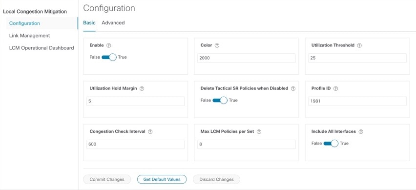
  1. After some time, the deployed TTE SR policies might no longer be needed. This occurs if the utilization will continue to be under the threshold without the LCM-initiated TTE tunnels. In this case, LCM generates new recommended actions to delete the TTE SR policy sets. Click Commit All to remove the deployed TTE SR policies.

    LCM Operational Dashboard - Delete Recommendation
  2. Click Commit All to remove the SR policies.

  3. Confirm the removal by viewing the topology map and SR Policy table.


Configure LCM

To enable and configure LCM:

Procedure


Step 1

From the main menu, choose Traffic Engineering > Local Congestion Mitigation.

Step 2

Toggle the Enable switch to True.

Step 3

Enter the required information. Hover the mouse pointer over Field Help icon to view a description of each field.

The following list describes additional field information:

  • Congestion Check Interval (seconds)—This value determines the interval at which LCM will evaluate the network for congestion. Under a steady state, when there are no recommendation commits, it uses this interval to re-evaluate the network to determine if changes are required to recommendations. For example, if the interval is set to 600 seconds (5 minutes), LCM will evaluate the network every 5 minutes for new congestion and determine whether a new recommendation or modifications to existing recommendations are needed. Examples of modifications can include removal or updates to individual policies that were previously recommended. Since network changes may take time for the information to stabilize and propagate to LCM, set the interval to no less than twice the SNMP collection cadence.

  • Advanced > Congestion Check Suspension Interval (seconds)—This interval determines the time to wait (after a Commit All is performed) before resuming congestion detection and mitigation. Since this interval should allow time for network model convergence, set the interval to no less than twice the SNMP collection cadence.

Step 4

Click Commit Changes.


Monitor LCM Operations
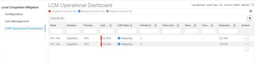
View the LCM Dashboard (Traffic Engineering > Local Congestion Mitigation > LCM Operational Dashboard) to monitor LCM operations. The LCM Operational Dashboard shows congested interfaces as defined by the configured utilization threshold. For each interface, it lists details such as current utilization, recommended action, status, expected utilization after committing recommendations, and so on. Hover the mouse pointer over Field Help icon to view a description of what type of information each column provides. From this dashboard, you can also preview and deploy TTE policy recommendations.

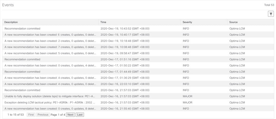
In addition to the LCM Operational Dashboard, you can click Show Events icon to view LCM events.

Use BWOpt to Optimize the Network

Bandwidth Optimization (BWOpt) provides closed-loop tactical traffic engineering (TTE) for segment routed policies by automatically detecting and mitigating congestion in your network. It achieves this through a real-time view of the network topology overlaid with a demand matrix built through telemetry-based Segment Routing Traffic Matrix (SRTM). The intent is to optimize bandwidth resource utilization by setting utilization thresholds on links. BWOpt uses the threshold interface utilization requested by the user and compares it to the actual utilization in the network. When interface congestion is detected by BWOpt, it attempts to reroute intent-based traffic from hot spots through the use of TTE SR policies which are deployed to the network via SR-PCE. As network conditions (topology and/or traffic) change over time, BWOpt continues to monitor interface utilization and manage any TTE SR policies deployed, including changing their paths and/or removing them from the network when deemed no longer necessary.

BWOpt Important Notes

Consider the following information when using BWOpt:

  • BWOpt will not shift traffic in existing SR-TE policies that it did not create. This may prevent it from being able to mitigate congestion if most of the traffic on the congested link is in non-BWOpt SR-TE policies.

  • BWOpt relies on the PCC's autoroute feature to steer traffic into the tactical SR-TE policies it creates. Autoroute is applied to these policies through the proper Profile ID option set in BWOpt (to align with configuration on the PCC associating that Profile ID with autoroute feature). This is critical to tactical SR policies shifting traffic away from congested links.

  • Enable BWOpt on single-level IGP domains only.

  • BWOpt uses simulated traffic based on measured SRTM data to determine link utilizations and when to mitigate congestion. The simulated interface utilization that BWOpt monitors should closely align with the SNMP-based interface utilization that is displayed in the UI. However, due to various factors, including SNMP polling cadence and rate averaging techniques, they may differ at times. This can result in scenarios like a link appearing to be congested in the UI and BWOpt not reacting.

  • BWOpt only creates tactical SR-TE policies on PCCs that are sources of SRTM telemetry data. Only these nodes (typically provider edge routers) provide the telemetry-based data needed to create simulated traffic demands in the internal model representing the traffic from that node to other PE nodes in the network.

  • Only solutions that produce interface utilization below the threshold (set across all interfaces) will be deployed. If BWOpt is unable to mitigate congestion across the entire network, it will not deploy any tactical SR-TE policies and a “Network Congested. BWOpt unable to mitigate.” alarm is raised. This alarm goes away when congestion either subsides on its own or can be addressed successfully through BWOpt tactical SR-TE policy deployments.

  • BWOpt temporarily pauses operation whenever the system is unavailable due to a restart or a rebuild of the topology from Topology Services. When this occurs, an alarm indicating this condition is set by BWOpt. During this time, BWOpt will not evaluate congestion in the network. All currently deployed tactical SR policies are maintained, but will not be modified or deleted. As soon as the model becomes available, the alarm is cleared and BWOpt will resume normal operation.

Automated Network Congestion Mitigation Example

This example demonstrates how Bandwidth Optimization (BWOpt) automatically mitigates network congestion by rerouting intent-based traffic without user intervention. In this example, the optimization intent is set to minimize the IGP metric.

The following BWOpt options are set (Traffic Engineering > Bandwidth Optimization > Configuration):
Figure 2. Bandwidth Optimization Configuration
Bandwidth Optimization Configuration
Below is a network with various devices and links that span the United States. Note that there are no SR-TE policies listed in the SR Policies table.
Figure 3. Example: Current Network
No SR policies displayed
Suppose the link between P3_NCS5501 and P4_NCS5501 goes down. Traffic moves towards other links causing congestion and exceeds the configured utilization threshold.
Figure 4. Example: Link Down Between P3 and P4 Nodes
Link Down
BWOpt recognizes the congestion and immediately calculates and deploys a tactical SR-TE policy. This new tactical SR-TE policy is listed in the SR Policies window.
Figure 5. Example: Tactical SR Policy Deployed
Tactical SR Policy Deployed

BWOpt continually monitors the network. When the links between P3_NCS5501 and P4_NCS5501 are back up, BWOpt will detect that the congestion (based on the defined criteria) has been mitigated. When the congestion falls under the set utilization threshold minus the utilization hold margin, the tactical SR-TE policy is automatically removed from the network.

You can also click Show Events icon to view events relating to instantiation and removal of tactical SR-TE policies created by BWOpt.

Configure Bandwith Optimization


Note

Bandwidth Optimization (BWOpt) is only available as part of the Advance License package.

After BWOpt is enabled, it monitors all interfaces in the network for congestion based on the configured utilization threshold. When the utilization threshold is exceeded, it automatically deploys tactical polices and moves traffic away from the congested links. When congestion is alleviated, BWOpt automatically removes the tactical SR policy.

Procedure


Step 1

From the main menu, choose Traffic Engineering > Bandwidth Optimization.

Step 2

Toggle the Enable switch to True.

Note 

LCM and Bandwidth Optimization cannot be enabled at the same time.

Step 3

Enter the required information. Hover the mouse pointer over Info icon to view a description of each field.

Step 4

Click Commit Changes. BWOpt begins to monitor network congestion based on the threshold and optimization intent that was configured.


Troubleshoot Bandwidth Optimization

BWOpt disables itself and issues an alarm when specific error conditions occur that hinder its ability to manage congestion properly and may lead to instability. The following table defines some of these conditions and possible causes to investigate. Additional details can be obtained for each error condition by referring to the BWOpt logs.

Table 1. Errors

Error Event Message

Possible Causes and Recommended Corrective Action

Optima Engine model error

The network model used by BWOpt from the Optimization Engine is corrupt or is missing key data that is needed to properly support BWOpt. Possible causes include network discovery issues or synchronization problems between the Optimization Engine and Topology Services. Try restarting the Optimization Engine pod to rebuild the model.

This error can also occur if the time required to deploy a tactical policy through SR-PCE, discover it, and add it to the model exceeds the Deployment Timeout option set for BWOpt. The default is 30 seconds which should suffice for small to medium sized networks. However, larger networks may require additional time.

PCE Dispatch unreachable

The deployment of a tactical policy to the network is not confirmed successful before the Deployment Timeout is exceeded. Increase the Deployment Timeout option to allow for additional time for deployments in larger networks.

Unable to deploy a tactical SR policy

A tactical SR policy deployment to SR-PCE was unsuccessful. There could be a variety of reasons for this. BWOpt and/or PCE Dispatch logs can provide some guidance as to the details of the failure. Confirm basic SR policy provisioning capability to the PCC via one of the SR-PCE providers is working.

Add Individual Interface Thresholds

Networks have many different links (10G, 40G, 100G) that require different thresholds to be set. To assign specific threshold values for individual interfaces when using LCM or Bandwidth Optimization, do the following:

Procedure


Step 1

From the main menu, choose one of the following:

  • Local Congestion Mitigation > Link Management

  • Bandwidth Optimization > Link Management

Step 2

Click Import icon.

Step 3

Click the Download sample configuration file link.

Step 4

Click Cancel.

Step 5

Open and edit the configuration file (sampleLcmLinkManagement.csv) you just downloaded. Replace the sample text with your specific node, interface, and threshold information.

Step 6

Rename and save the file.

Step 7

Navigate back to the Link Management window.

Step 8

Click Import icon and navigate to the CSV file you just edited.

Step 9

Click Import.

Step 10

Confirm that the information appears correctly in the Link Management window.