|
Auto repair solution
|
If set to True, LCM will automatically delete any down, failed, or uncommitted LCM TTE policies. This option is mainly to address a failure
in a policy.
If this option is disabled, and the Urgency status of the recommendation shown in the LCM Operational Dashboard is High, then the recommended solution is a candidate for the Auto repair solution. This means that a network failure will most likely occur if the solution is not deployed.
|
|
Stay in area
|
Restricts bypass LSP paths to stay within the mitigated area for OSPF or levels for ISIS.
|
|
Adjacency hop type (seconds)
|
If set to Protected, LCM will create SR policies using protected adjacency SIDs. This allows for Topology-Independent Loop-Free Alternate (TI-LFA)
to compute a path for any adjacency failures.
This option should only be set to Protected if all nodes in the same IGP area as LCM is operating are strict SPF SID capable.
|
| Optimization objective |
LCM calculates tactical SR policies based on the metric type chosen to minimize.
|
| Deployment timeout |
Enter the maximum number of seconds allowed to confirm deployment of tactical SR policies.
|
|
Congestion check suspension interval (seconds)
|
This interval determines the time to wait (after a Commit all is performed) before resuming congestion detection and mitigation. Since this interval should allow time for network model
convergence, set the interval to no less than twice the SNMP collection cadence.
|
|
Over-provisioning factor (OPF)
|
This option helps address unequal ECMP traffic distribution (elephant flows). This value determines the percentage of extra
traffic that should be accounted for when computing a path for a by-pass policy. If LCM needs to divert i amount of traffic due to congestion, then it will search for a path that can support x * (1 + OPF) traffic. For more information, see LCM calculation workflow. The default value is 0.
|
|
Uneven ECMP traffic threshold
|
The percentage of sensitivity to detect uneven amounts of traffic across solution bypass tunnels.
|
|
Debug optimizer
|
Enable debug optimizer to log plan files to the Crosswork Network Controller file system. Files are saved to the maximum number
of files you specify in Debug opt max plan files.
|
|
Maximum segment hops
|
Prior to using this option, you must create device tag groups to which you want to assign certain MSD values. For information
on creating tags and assigning them to devices, see the Cisco Crosswork Network Controller Administration Guide
When calculating bypass TTE policies, LCM uses the effective Maximum SID Depth (MSD) value (as entered here) for specified
device tags. You can assign up to five device tags with specific MSD values.
A 0 value will not result in a solution. Setting a 0 value is equivalent to LCM monitoring and indicating when there is congestion in the network without providing a recommendation.
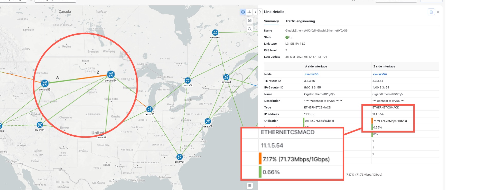
The system learns from SR-PCE the MSD for each platform advertising the hardware limit in the IGP and BGP-LS. It represents
the hardware limit that can be imposed exclusive of any service/transport/special labels. Therefore, you may want to use this
new option to assign less than the advertised MSD value that LCM can use for bypass TTE policy calculation. To view the MSD
value for a device, navigate to the Traffic Engineering topology map and click on the device. From the Device details page, click .
|
|
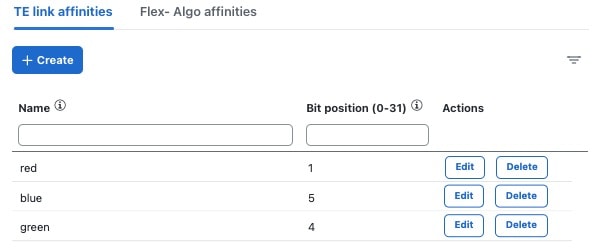
Affinity
|
You can configure LCM to include or exclude links by using affinities to route data based on specific criteria. For example,
if an affinity is excluded, LCM will try to alleviate a congested link by diverting traffic using paths that do not have that
affinity. Affinities must already be configured on devices and then mapped using the Crosswork Network Controller UI in order to see the list of affinity names. See Example: Cisco IOS-XR affinity configuration and Configure link affinities.
|

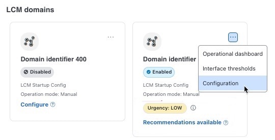
 > Configuration.
 Feedback