SR Circuit-Style Manager (CSM)

SR Circuit-Style Manager (CSM)

The SR Circuit-Style Manager (CSM) provides a bandwidth-aware Path Computation Element (PCE) for computing circuit-style Segment Routing Traffic Engineering (CS SR-TE) policy paths.

The CSM performs centralized bookkeeping of bandwidth resources across the network and computes paths that meet strict bandwidth requirements while adhering to user-specified constraints such as disjointness and latency minimization. Additionally, the CSM allows users to monitor bandwidth resource levels and identify where resources are running low. It manages and visualizes circuit-style SR-TE policies on the network topology map, ensuring that the best failover bidirectional paths are computed with the requested bandwidth and other constraints

Advantages of using circuit-style SR-TE policies

Circuit-style SR-TE policies:

  • are bidirectional, co-routed and designed to carry high-priority or critical services traffic over packet-based networks that require committed bandwidth with protected paths,

  • ensure reliability and no impact on service-level agreements (SLAs) due to changing network loads, and

  • do not require the maintenance of network states at intermediate routers, nor does it require complex multiprotocols to be implemented.

Important considerations for circuit-style SR-TE policies in Crosswork Network Controller

This section outlines the scope of support for circuit-style SR-TE policies within Crosswork Network Controller. It includes the necessary requirements and constraints on policy attributes for each circuit-style SR-TE policy and describes the processing logic used during path reversions.

Access requirements for circuit-style SR-TE policy provisioning

To provision a circuit-style SR-TE policy, you must have write-access to the head-end device based on Device Access Groups and assigned roles. Only circuit-style SR-TE admin users can modify circuit-style SR-TE configuration settings. For more information on Role-based Access Control (RBAC) and task permissions, see the "Cisco Crosswork Network Controller Administration Guide".

Attribute constraints

You set policy attribute values when you create a circuit-style SR-TE policy using either the device's command line interface (CLI) or through Cisco Crosswork Network Controller UI provisioning using Cisco Network Services Orchestration (NSO). To view a device CLI configuration example, see Configure circuit-style SR policies.

This table outlines the requirements for each policy attribute and ow changes affect them. All attributes listed function as constraints. Each attribute aligns with configuration elements that Crosswork Network Controller utilizes to manage the computation of circuit-style path hops. Each value serves as a constraint for path computation or optimization, either defining a necessary path property or eliminating potential path options.

Table 1. Attribute constraints

Attribute

Description

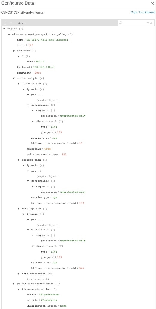
Policy path protection

The path protection constraint is required for both sides of a circuit-style SR-TE policy.

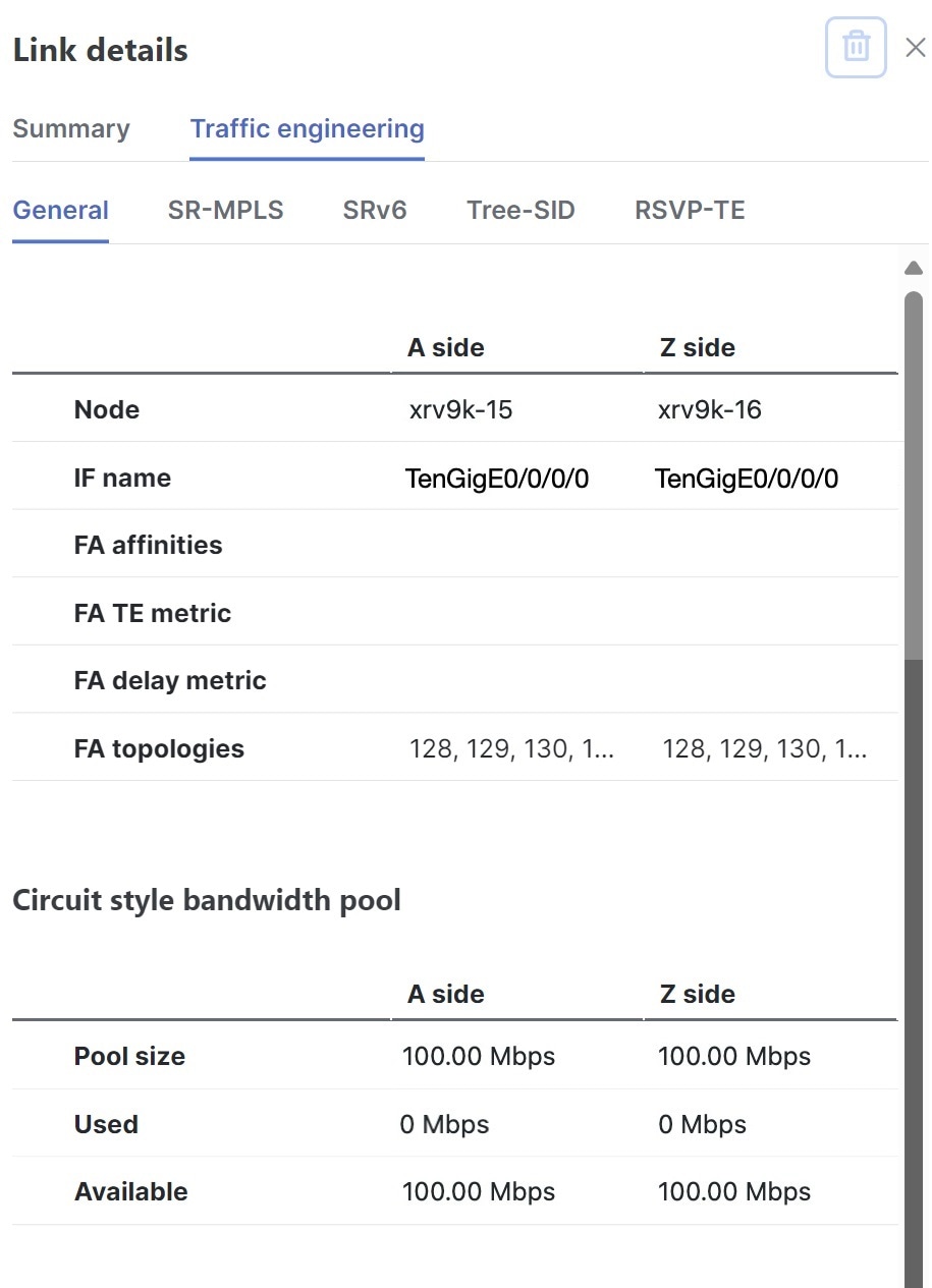
Bandwidth constraint

  • The bandwidth constraint is required and must be the same on both sides of a circuit-style SR-TE policy. Changes to bandwidth can be applied to existing policies with the following outcomes:

    • After configuring the new bandwidth on both sides, the system evaluates the path without recomputing it.

    • If the new bandwidth is higher, the system checks the current path for sufficient resources. If all paths can support the new bandwidth, the same path is returned with the updated bandwidth value, indicating to the path computation client (PCC) that it was successful. If any path cannot support the new bandwidth, the old bandwidth value is returned, indicating failure. This evaluation is only retried if the bandwidth changes again.

    • If the bandwidth is lower, the system returns the same path with the new bandwidth value to indicate to the PCC that it was successful.

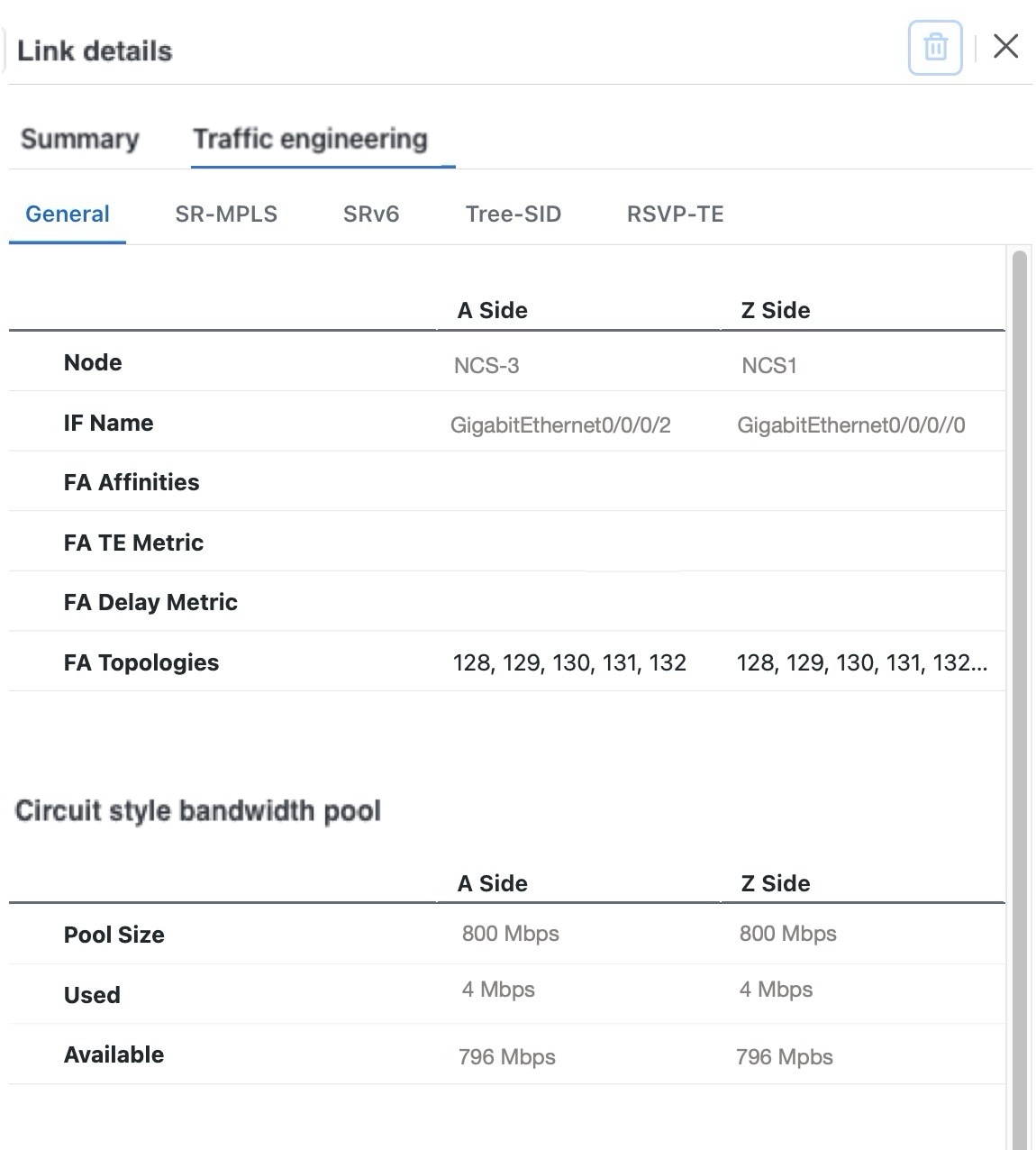
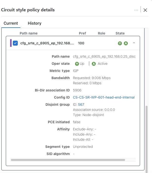
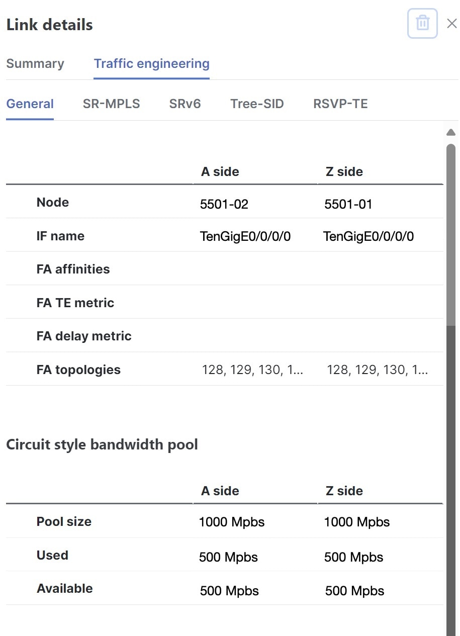
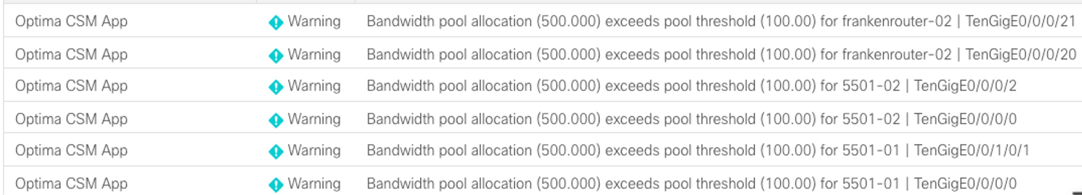
  • When you view the policy details, the user interface shows both the requested and reserved bandwidth under each candidate path. These values can differ if the requested bandwidth is increased but there is insufficient available circuit-style pool bandwidth along one or more paths.

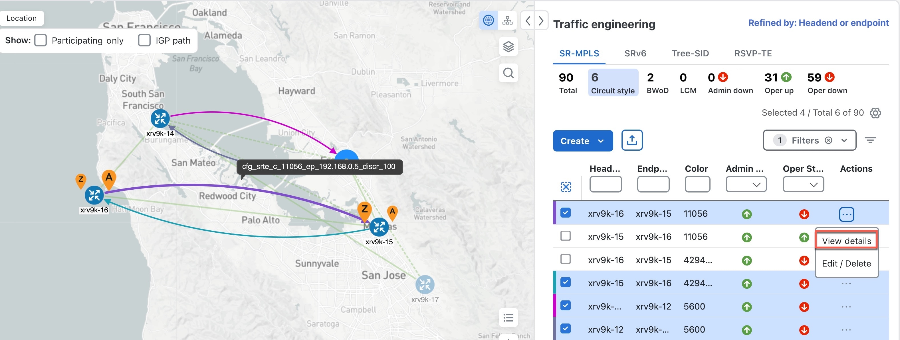
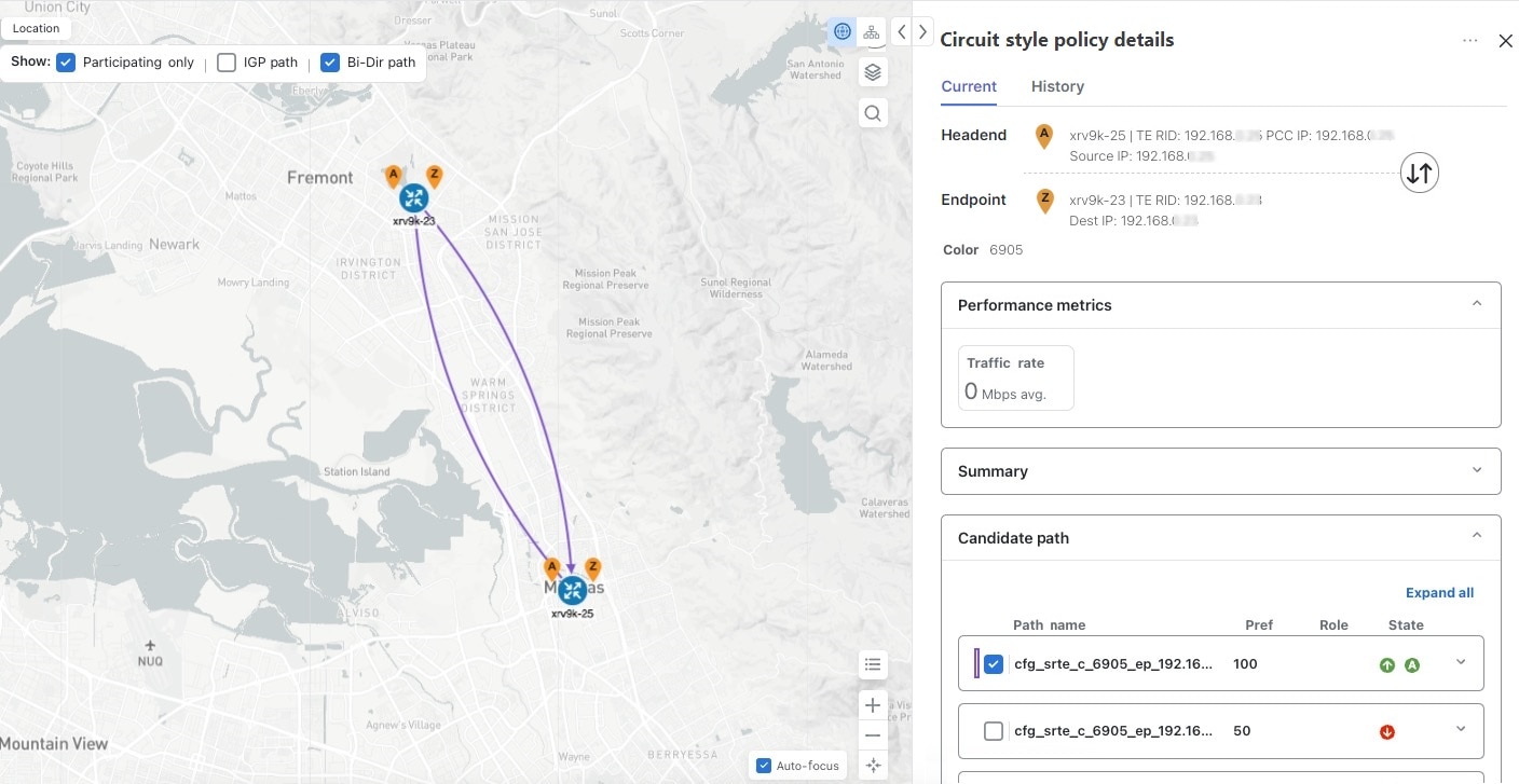
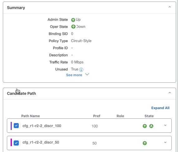
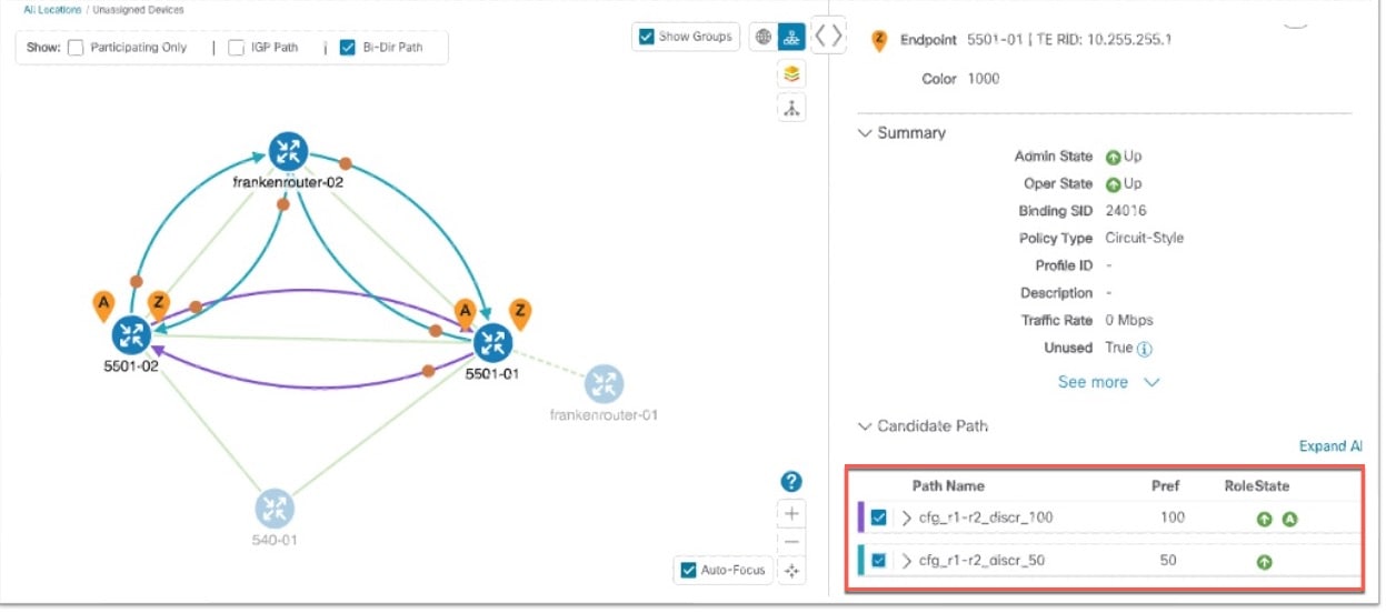
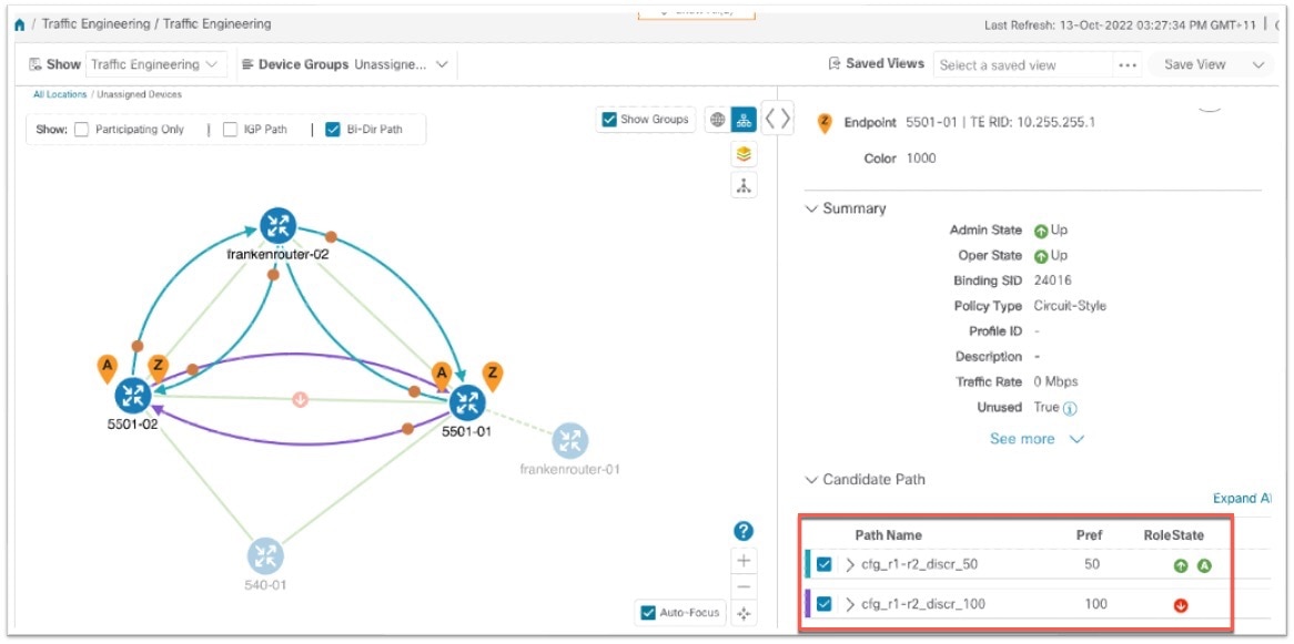
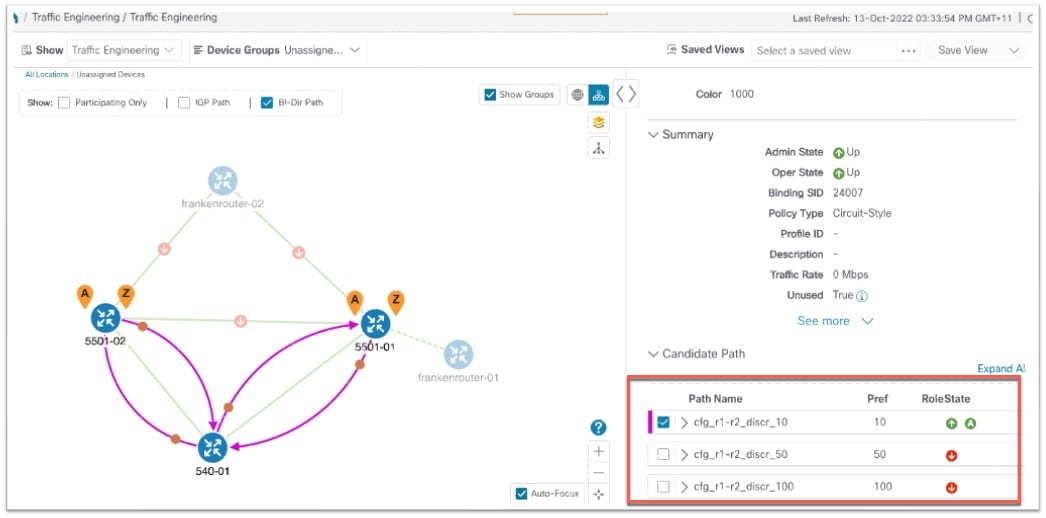
Candidate paths and roles

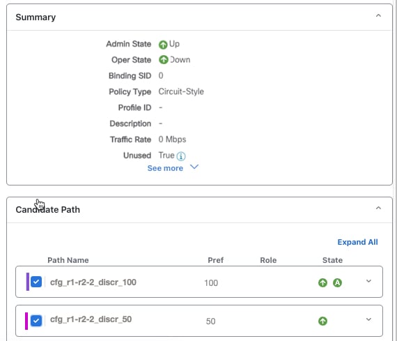
  • The Working path is defined as the highest preference Candidate Path (CP).

  • The Protect path is defined as the CP of the second highest preference.

  • The Restore path is defined as the lowest preference CP. The headend must have backup-ineligible configured.

  • CPs of the same role in each direction must have the same CP preference.

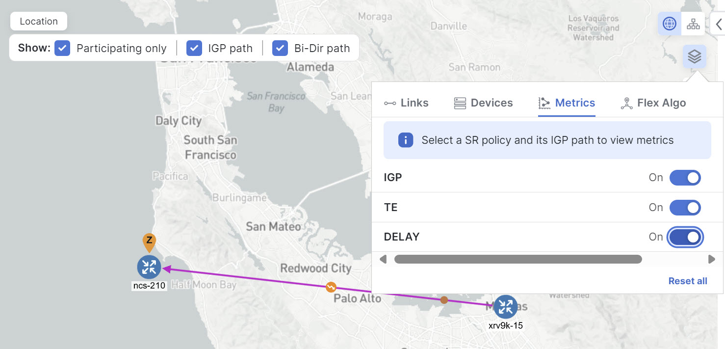
Bi-directional paths
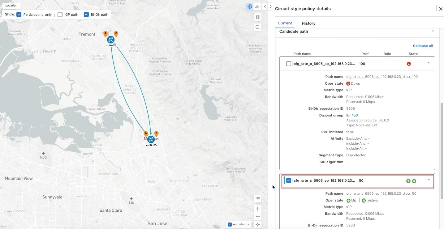
  • All paths must be configured as co-routed.

  • Paths of the same role on both sides must have the same globally unique bi-directional association ID.

Disjointness

The disjoint policy is used to compute two lists of segments that steer traffic from two source nodes to two destination nodes along disjoint paths. The disjoint type refers to the resources the two computed paths should not share.
  • The supported disjoint path types are:

    • Link: Links are not shared on the computed paths.

    • Node: Nodes are not shared on the computed paths.

    • SRLG: Links with the same Share Risk Link Group (SRLG) value are not shared on the computed paths. These links rely on a common resource, making them susceptible to the same potential failures. This setting specifies that the Working and Protect paths cannot use links that are part of the same SRLG.

    • SRLG-node: SRLG and nodes are not shared on the computed paths.

  • The disjoint type used must be the same in both directions of the same policy.

  • Working and Protect paths on the same PCC must be configured with a disjointness constraint using the same disjoint association ID and disjointness type.

  • The disjointness association ID for a Working and Protect path pair in one direction must be unique when compared with the corresponding pair in the opposite direction.

  • The Restore path must not have a disjointness constraint set.

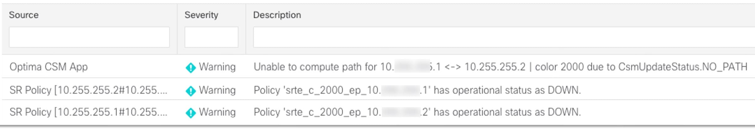
  • Crosswork Network Controller follows strict fallback behavior for all Working and Protect path disjointness computations. This means that if node type disjointness is configured but no path is available, the system makes no automatic attempt to compute a less restrictive link type disjoint path.

Metric type

Only the TE, IGP, hop count, and latency metric types are supported. The metric type must match Working, Protect and Restore paths in both directions.

Segment constraints

  • All Working, Protect, and Restore paths must have the following segment constraints:

    • protection unprotected-only

    • adjacency-sid-only

  • To ensure persistency through link failures, configure static adjacency SIDs on all interfaces that might be used by circuit-style SR-TE policies.

Unsupported configurations

These configurations are not supported:

  • metric bounds,

  • SID-Algo contraints,

  • partial recovery for devices running IOS XR 7.8.x,

  • multiple circuit style SR-TE policies between the same nodes with the same color but different endpoint IP addresses, and

  • state-sync configuration between PCEs of a high availability pair

Path computation behavior

The system computes paths for circuit style policies only after a complete bi-directional, path-protected set of candidate paths has been delegated, including Working and Protect paths on both sides.

Bandwidth availability and path delegation

Path computation relies on bandwidth availability. If insufficient bandwidth prevents path establishment, the SR Circuit-Style Manager will retry every 30 minutes until a solution is found or circuit style SR-TE is disabled.

Restore path computation

The Restore path is computed only after the Working and Protect paths go down. Use the configurable delay timer to set the wait period post-delegation, allowing topology and policy state changes to propagate before computation.

Path optimization and limitations

Automatic path re-optimization is unavailable for topology or LSP state changes and periodic events. Path configurations must be manually adjusted as needed.

Supported path computation scenarios

Path computation supports Intra/Inter-area and Intra/Inter IGP Domain scenarios. Inter-AS path computation is not supported, requiring manual configuration for such cases.

Path reversion

Reversion behavior

Reversion behavior is controlled by the configuration of the WTR lock timer option under the Protect and Revert paths (it is not relevant for the Working path):

  • No lock configuration: Revert after a default 5-minute lock

  • Lock with no duration specified: No reversion

  • Lock duration <value>: Revert after the specified number of seconds

Reversion logic

Path reversion depends on the initial state of the Working, Protect, and Restore paths and the events affecting each path. The scenarios in the following table provide examples of typical reversion behavior.

Table 2. Path reversion scenarios

Initial State

Events

Behavior

Working path is down, Protect path is up/active

Working path comes back up

  1. Working path recovers to up/standby state.

  2. Each PCC moves the Working path to active after the WTR timer expires.

  3. Protect path moves to up/standby.

Working path is down, Protect path is down, Restore path is up/active

Working path comes back up, then Protect path comes back up

  1. Working path recovers and goes to up/active state

  2. Restore path is removed

  3. Protect path recovers and goes to up/standby

Working path is down, Protect path is down, Restore path is up/active

Protect path comes back up, then Working path comes back up

On side A: The Working path failure is local (the first Adj SID in the SegList is invalid):

  1. Protect path recovers and goes to up/active.

  2. Restore path is removed.

  3. Working path recovers and goes to up/standby.

  4. Each PCC moves the Working path to active after the WTR timer expires, Protect path goes to up/standby.

On side Z: Working path failure is remote (first Adj SID in SegList is valid):

  1. Protect path recovers but is not brought up, Restore path remains up/active.

  2. Working path recovers and goes up/active.

  3. Restore path is removed.

  4. Protect path goes to up/standby.

Set up CS SR-TE policy visualization workflow

Complete these steps to view circuit style Segment Routing Traffic Engineering (CS SR-TE) policies on the topology map.

Procedure


Step 1

Enable SR Circuit-Style Manager

Step 2

Configure circuit-style SR policies on the device.

Step 3

Verify that the CS SR-TE policies appear in the Traffic engineering table.

Choose Services & Traffic Engineering > Traffic Engineering > SR-MPLS > Circuit-style.

Step 4

From the topology map, click a participating CS SR-TE node and verify that the reserved bandwidth pool settings you defined in the first step are configured properly.

Choose Links > link-type-entry > Traffic engineering > General. See Review circuit-style SR-TE policy bandwidth utilization.


Enable SR Circuit-Style Manager

To manage and visualize circuit-style SR-TE policies on the topology map, you must first enable the SR Circuit-Style Manager (CSM) and set bandwidth reservation settings.

When enabled, the CSM computes the best failover bidirectional paths with the requested bandwidth and other constraints defined in the circuit-style SR policy configuration between two nodes.

Complete these steps to enable SR Circuit-Style Manager.

Procedure


Step 1

From the main menu, choose Traffic Engineering > Circuit Style SR-TE > Configuration.

Step 2

Set Enable to True.

Step 3

Enter the required bandwidth pool size and threshold information. Additional field information is listed in this table. See Effects of surpassing bandwidth reservation limits.

Field Description

Basic

Link CS BW Pool Size

The percentage of each link's bandwidth reserved for circuit-style SR-TE policies.

Link CS BW Min Threshold

The Link CS BW Pool utilization percentage beyond which a threshold crossing event notification will be generated.

Advance

Validation Interval

This is the interval that the CSM policy will wait before the bandwidth that is reserved for an undelegated policy is returned to the circuit-style SR-TE policy bandwidth Pool.

Timeout

The duration until which the CSM will wait for the delegation request, to generate a notification.

Restore Delegation Delay

The duration until which the CSM will pause before processing a restore path delegation.

Step 4

To save the configuration, click Commit Changes.


What to do next

Configure circuit-style SR policy configurations either manually on the device (see Configure circuit-style SR policies) or through Cisco Crosswork Network Controller.

Configure circuit-style SR policies

A circuit-style SR policy configuration must include the destination endpoint, the amount of requested bandwidth, and the bidirectional attribute (see Important considerations for circuit-style SR-TE policies in Crosswork Network Controller for additional requirements or notable constraints). The configuration should also include a Performance Measurement Liveness (PM) profile. A PM profile enables proper detection of candidate path liveness and effective path protection. PCCs do not validate past the first SID, so without PM, the path protection will not occur if the failure in the circuit-style SR policy candidate path is not the first hop in the segment list. For more information, see Configuring SR Policy Liveness Monitoring.

This section provides guidance on how to manually configure a circuit-style SR policy and a PM profile on a device.

Procedure


Step 1

If applicable, enable the hardware module on the device for PM configuration.

Example:

hw-module profile offload 4

reload location all

Step 2

Configure the PM profile.

Example:

performance-measurement
 liveness-profile sr-policy name CS-active-path
  probe
   tx-interval 3300
  !
npu-offload enable   !! Required for hardware Offload only
  !
 !
 liveness-profile sr-policy name CS-protect-path
  probe
   tx-interval 3300
  !

npu-offload enable   !! Required for hardware Offload only
  !
 !
!

Step 3

Configure the Circuit Style SR policy with the PM profile. All configurations shown in the example are required in order for CSM to manage the circuit-style SR-TE policy. Entries that are defined by the user are italicized. See Important considerations for circuit-style SR-TE policies in Crosswork Network Controller for additional requirements or notable constraints.

Example:

segment-routing
 traffic-eng
  policy cs1-cs4

   performance-measurement
    liveness-detection
     liveness-profile backup name CS-protect      !! Name must match liveness profile defined for Protect path
     liveness-profile name CS-active               !! Name must match liveness profile defined for Active path
    !
   !
   bandwidth 10000
   color 1000 end-point ipv4 192.168.20.4
   path-protection
   !
   candidate-paths
    preference 10
     dynamic
      pcep
      !
      metric
       type igp
      !
     !
     backup-ineligible
     !

     constraints
      segments
       protection unprotected-only
       adjacency-sid-only
      !
     !
     bidirectional
      co-routed
      association-id 1010
     !
    !
    preference 50
     dynamic
      pcep
      !
      metric
       type igp
      !
     !
     constraints
      segments
       protection unprotected-only
       adjacency-sid-only
      !
      disjoint-path group-id 3 type node, srlg, or link
     !
     bidirectional
      co-routed
      association-id 1050
     !
    !
    preference 100
     dynamic
      pcep
      !
      metric
       type igp
      !
     !
     constraints
      segments
       protection unprotected-only
       adjacency-sid-only
      !
      disjoint-path group-id 3 type node, srlg, or link
     !
     bidirectional
      co-routed
      association-id 1100
     !
    !

   !
  !

 !
!

Review circuit-style SR-TE policy bandwidth utilization

Complete these steps to verify that the reserved bandwidth pool settings (defined when enabling CSM, see Enable SR Circuit-Style Manager) are correctly configured. You can also view current circuit-style SR-TE bandwidth utilization and how much is still available for use.

Procedure


Step 1

From the main menu, choose Services & Traffic Engineering > Traffic Engineering > SR-MPLS and click Circuit style. The Traffic engineering table lists all circuit-style SR-TE policies.

Step 2

Check the check box next to the circuit-style SR-TE policy you are interested in.

Step 3

From the topology map, click a participating circuit-style SR-TE policy node.

Step 4

From the Device details page, choose Links > link-type-entry > Traffic engineering > General.

Under Circuit Style bandwidth pool, you can see

  • the reserved bandwidth pool size,

  • the amount of bandwidth currently being used, and

  • amount of bandwidth, allocated to circuit-style SR-TE policies, that is still available.

This example shows the reserved bandwidth pool size as 800 Mbps for NCS-3 and NCS1. The configured settings were earlier defined as 80% for the bandwidth pool size. Since the interface is 1 Gbps, we can confirm that CSM has correctly allocated 80% of the bandwidth for circuit-style SR-TE policies for these interfaces.
Figure 1. CS SR policy bandwidth pool

CS SR Policy Bandwidth Pool

View circuit-style SR-TE policy information

Complete these steps to view circuit-style SR-TE these policy details such as the endpoints, bandwidth constraints, IGP metrics, and candidate (Working and Protect) paths.

Procedure


Step 1

From the main menu, choose Services & Traffic Engineering > Traffic Engineering > SR-MPLS and click Circuit style.

Figure 2. Select Circuit style tab

Select Circuit Style Tab

The table lists all circuit-style SR-TE policies.

Step 2

From the Actions column, choose More icon > View Details for one of the circuit-style SR-TE policies.

Note


You cannot edit or remove circuit-style SR-TE policy configurations that have been created directly on the device.

Figure 3. View circuit-style SR-TE policy details

View Circuit Style SR-TE Policy Details

The Circuit style policy details page is displayed on the side panel. By default, the candidate path with an "active" state is displayed in the topology map. An active state is designated with a green "A" icon under State, indicating it is currently the operational active path. The map also has the Bi-Dir path checkbox checked by default, showing the bidirectional paths. The Candidate path list displays the candidate path with an active status (path that takes traffic) and other candidate paths.

Figure 4. CS-SR policy details summary

CS-SR Policy Details Summary

Note


The Bandwidth Constraint value can differ from the bandwidth you requested if the value is increased and insufficient resources exist to satisfy demand on all Working and Protect candidate paths.

Step 3

View Candidate path configuration details.

  1. The Circuit style policy details window allows you to drill down to view more information about the candidate paths. You can also copy the URL and share this information with others.

    The Working path (highest preference path) with an operational state (Oper state) "Up" will always have an active state indicating that it takes traffic (see CSM path failure management). If the Working path goes down, the Protect path is activated. In this example, the Protect path (with preference 50) is active and displayed on the topology map. Click Expand all to view more information about both paths.

    Figure 5. Candidate path on topology map

    Candidate Path on Topology Map

    Note

     
    • First preference paths are shown as purple links.

    • Second preference paths are shown as blue links.

    • Third preference paths are shown as pink links.

    If the circuit-style SR-TE policy configuration was done through Cisco Crosswork Network Controller, you have the option to view the circuit-style SR-TE policy configuration. To see the configuration, click the link next to Config ID. For example:
    Figure 6. View Candidate path details

    View Candidate Path Details
    Here is a sample of a circuit-style policy configuration. See Configure circuit-style SR policies.
    Figure 7. Circuit-style policy configuration example

    Circuit Style Policy Configuration Example

Step 4

To view the physical path and metrics between endpoints of the selected circuit-style SR-TE policies, click Display Preferences icon to turn applicable metrics on and check the IGP path checkbox.

Figure 8. IGP metrics

IGP Metrics

Trigger CSM to recalculate a circuit-style SR-TE Policy

Circuit-style SR-TE policies are static in nature, meaning once the paths are computed, they will not be automatically reoptimized based on topology or operational status changes that may affect their paths. You can reoptimize a Working and Protect path (not a Restore path) after the policy's operational status went from down to up or if bandwidth size and requirement changes have been configured.

Complete these steps to manually trigger CSM to recalculate a CS SR-TE policy.

Procedure


Step 1

From the main menu, choose Services & Traffic Engineering > Traffic Engineering > SR-MPLS and click Circuit style. The Traffic engineering table lists all circuit-style SR-TE policies.

Step 2

From the Actions column, choose More icon > View Details for the circuit-style SR-TE policies you want CSM to recalculate a path for again.

Step 3

From the top-right corner, choose More icon > Reoptimize.


Effects of surpassing bandwidth reservation limits

CSM discovers and updates the available and reservable bandwidth in the network. CSM maintains an accounting of all bandwidth reservations provided for CS SR policies to ensure that the total reserved bandwidth on all interfaces remains at or below the network-wide resource pool (bandwidth pool size).

This topic provides examples of how CSM handles policies that exceed the bandwidth pool size or bandwidth alarm threshold set on the CSM Configuration page.

Example: Bandwidth utilization surpasses defined threshold

  • Link CS Bandwidth Pool Size: 10%

  • Link CS Bandwidth Minimum Threshold: 10%

In this example, the bandwidth pool size for the 10 Gbps ethernet interfaces is 1Gbps and the alarm threshold is set at 100 Mbps (10% of pool size).

  1. A circuit-style SR-TE policy from node 5501-02 to node 5501-01 (r02 - r01) is created with a bandwidth of 100 Mbps.

    Figure 9. CS-SR policy 10 Mbps up

    CS-SR Policy 10 Mbps Up
  2. Later, the requested bandwidth configured for the policy is increased to 500 Mbps. CSM determines the additional bandwidth along the existing path is available and reserves it.

    Figure 10. CS-SR policy 500 Mbps up

    CS-SR Policy 500 Mbps Up
  3. Since the bandwidth utilization (500 Mbps) with the updated policy is above the configured pool utilization threshold (100 Mbps), an event is triggered.

    Figure 11. Threshold alerts

    Threshold Alerts

Example: Bandwidth pool size and utilization exceeded

  • Link CS Bandwidth Pool Size: 10%

  • Link CS Bandwidth Minimum Threshold: 90%

In this example, the bandwidth pool size for the 10 Gbps ethernet interfaces is 1Gbs and the alarm threshold is set for 900 Mbps.

  1. An existing circuit-style SR-TE policy from node 5501-02 to node 5501-01 (r02 - r01) uses a bandwidth of 500 Mbps.

  2. Later, a new policy requiring a bandwidth of 750 Mbps with a path from node 5501-02 to node 5501-01 to 5501-2 (r02 - r01- r2) is requested. The only paths available between these two nodes are the paths computed for the first CS policy.

    • CSM cannot compute a path for the new circuit-style SR-TE policy r02 - r01 - r2 and remains operationally down. CSM will try again every 30 minutes to find a path that meets the bandwidth requirements.

      Figure 12. CS-SR policy exceeds bandwidth pool size

      CS-SR Policy Exceeds Bandwidth Pool Size
    • Alerts are triggered.

      Figure 13. Threshold alerts

      Threshold Alerts
  3. Later, the circuit-style SR-TE policy r02 - r01- r2 is updated and only requires 10 Mbps. The following behaviors occur:

    • Since the total bandwidth required for the two policies (10 Mbps + 500 Mbps = 510 Mbps) now requires less than the bandwidth pool size (1Gbps), circuit-style SR-TE policy r02 - r01 - r2 receives a path computed by CSM and becomes operationally up.

      Figure 14. Updated CS-SR policy - operational

      Updated CS-SR Policy Operational
    • Since the second circuit-style SR-TE policy with the reduced bandwidth is now provided a path by CSM, alerts are cleared.

      Figure 15. Cleared alerts

      Cleared Alerts

CSM path failure management

Cisco Crosswork computes paths for circuit-style SR-TE policies only after a complete bidirectional, path-protected set of candidate paths has been delegated. Three types of candidate paths are used during path failures:

  • Working—This candidate path has the highest preference value.

  • Protect—This candidate path has the second-highest preference value. If the Working path goes down, the Protect path (with the lower preference value) is activated. After the Working path recovers, the Protect path remains active until the default lock duration expires.

  • Restore—This candidate path has the lowest preference value. Crosswork computes the Restore path only after the Working and Protect paths are down. You can control how long after Restore paths are delegated from both sides to wait before the path is computed (see Enable SR Circuit-Style Manager). This delay allows topology and policy state changes to fully propagate to Crosswork in cases where these changes triggered the Restore path delegation.

You can configure Performance Measurement (PM) to address path failures effectively and switch from the Working path to the Protect path. For more information, see Configure circuit-style SR policies.

Examples


Note


Illustrations are for demonstration purposes only and may not always reflect the exact UI or data described in the workflow content. If you are viewing the HTML version of this guide, click the images to view them in full size.


The following image shows that the Working and Protect paths of the circuit-style SR-TE policy are operational. The active path is indicated by the "A" icon.
Figure 16. Initial Candidate Paths

Initial Candidate Paths
When a Working path having an active status goes down, the Protect path immediately becomes "active." When the Working path recovers, the Protect path moves to up/standby, and the Working path (with preference 100 in the example) becomes active.
Figure 17. Protected Path Becomes Active

Protected Path Becomes Active
When both the Working and Protect paths go down, CSM calculates a Restore path, which becomes active. The Restore path only appears in this specific scenario. Note that the Restore path has the lowest preference value of 10 in the example. If the Working or Protected paths become operational again, the Restore path will no longer be visible on the topology map and will be removed from the Candidate path list.
Figure 18. Restore Path

Restore Path