Integrate SR-PCE

This chapter contains the following topics:

SR-PCE Integration Workflow

This section explains the steps in integrating Cisco SR-PCE with Crosswork Network Controller.

The compatible versions of SR-PCE are Cisco IOS XR 7.11.1.

1. Install the compatible version of Cisco SR-PCE

Select the type of SR-PCE (for VMware ESXi or AWS) and follow the relevant install instructions in the Cisco IOS XRv 9000 Router Installation Guide.

2. Configure SR-PCE

Follow the instructions in Configure SR-PCE.

3. Add SR-PCE provider and verify connectivity

Follow the instructions in Add Cisco SR-PCE Providers.

Configure SR-PCE

This section explains how to configure SR-PCE after you have installed it.


Note


The Cisco IOS XRv 9000 is the recommended platform to act as the SR-PCE.


Table 1. Configure SR-PCE

Step

Command or Action

Description

1

configure

Example:

RP/0/RP0/CPU0:router# configure

Enters mode.

2

pce

Example:

RP/0/RP0/CPU0:router(config)# pce

Enables PCE and enters PCE configuration mode.

3

address ipv4 address

Example:

RP/0/RP0/CPU0:router(config-pce)# address ipv4 192.168.0.1

Configures a PCE IPv4 address.

4

state-sync ipv4 address

Example:

RP/0/RP0/CPU0:router(config-pce)# state-sync ipv4 192.168.0.3

Configures the remote peer for state synchronization.

5

tcp-buffer size size

Example:

RP/0/RP0/CPU0:router(config-pce)# tcp-buffer size 1024000

Configures the transmit and receive TCP buffer size for each PCEP session, in bytes. The default buffer size is 256000. The valid range is from 204800 to 1024000.

6

password {clear | encrypted} password

Example:

RP/0/RP0/CPU0:router(config-pce)# password encrypted pwd1

Enables TCP MD5 authentication for all PCEP peers. Any TCP segment coming from the PCC that does not contain a MAC matching the configured password will be rejected. Specify if the password is encrypted or clear text.

Note


TCP-AO and TCP MD5 are never permitted to be used simultaneously.

7

tcp-ao key-chain [include-tcp-options] [accept-ao-mismatch-connection]

Example:

RP/0/RP0/CPU0:router(config-pce)# tcp-ao pce_tcp_ao include-tcp-options

Enables TCP Authentication Option (TCP-AO) authentication for all PCEP peers. Any TCP segment coming from the PCC that does not contain a MAC matching the configured key chain will be rejected.

  • include-tcp-options—Includes other TCP options in the header for MAC calculation.

  • accept-ao-mismatch-connection—Accepts connection even if there is a mismatch of AO options between peers.

Note


TCP-AO and TCP MD5 are never permitted to be used simultaneously.

8

segment-routing {strict-sid-only | te-latency}

Example:

RP/0/RP0/CPU0:router(config-pce)# segment-routing strict-sid-only

Configures the segment routing algorithm to use strict SID or TE latency.

Note


This setting is global and applies to all LSPs that request a path from this controller.

9

timers

Example:

RP/0/RP0/CPU0:router(config-pce)# timers

Enters timer configuration mode.

10

keepalive time

Example:

RP/0/RP0/CPU0:router(config-pce-timers)# keepalive 60

Configures the timer value for locally generated keep-alive messages. The default time is 30 seconds.

11

minimum-peer-keepalive time

Example:

RP/0/RP0/CPU0:router(config-pce-timers)# minimum-peer-keepalive 30

Configures the minimum acceptable keep-alive timer that the remote peer may propose in the PCEP OPEN message during session establishment. The default time is 20 seconds.

12

reoptimization time

Example:

RP/0/RP0/CPU0:router(config-pce-timers)# reoptimization 600

Configures the re-optimization timer. The default timer is 1800 seconds.

13

exit

Example:

RP/0/RP0/CPU0:router(config-pce-timers)# exit

Exits timer configuration mode and returns to PCE configuration mode.

What to do next:

Return to the installation workflow:

Sample SR-PCE config

This is a sample SR-PCE configuration:

pce
address ipv4 1.1.1.98
api
  user cisco                              {This is the username and password that the credential profile used for the PCE will need to have for HTTP}
   password encrypted 032752180500701E1D48
!

Add Cisco SR-PCE Providers

Cisco Segment Routing Path Computation Elements (Cisco SR-PCE) providers supply device discovery, management, configuration-maintenance and route-calculation services to the Cisco Crosswork applications. At least one SR-PCE provider is required in order to learn and discover SR policies, Layer 3 links, and devices. You have the option to configure a second SR-PCE as a backup. Both SR-PCE devices must be connected to the same network as Crosswork Network Controller does not support managing more than one domain.


Note


To enable Cisco Crosswork application access to an SR-PCE as an SDN controller on the management domain, SR-PCE needs to be added as a provider.


Follow the steps below to add (through the UI) one or more instances of Cisco SR-PCE as providers.

Before you begin

You will need to:
  • Configure a device to act as the SR-PCE. See SR configuration documentation for your specific device platform to enable SR (for IS-IS or OSPF protocols) and configure an SR-PCE (for example: Segment Routing Configuration Guide for Cisco NCS 540 Series Routers).

  • Create a credential profile for the Cisco SR-PCE provider. This should be a basic HTTP text-authentication credential (currently, MD5 authentication is not supported). If the Cisco SR-PCE server you are adding does not require authentication, you must still supply a credential profile for the provider, but it can be any profile that does not use the HTTP protocol.

  • Know the name you want to assign to the Cisco SR-PCE provider. This is usually the DNS hostname of the Cisco SR-PCE server.

  • Know the Cisco SR-PCE server IP address.

  • Know the interface you want to use to communicate between Cisco SR-PCE and the Cisco Crosswork application server.

  • Determine whether you want to auto-onboard the devices that Cisco SR-PCE discovers and, if so, whether you want the new devices to have their management status set to off, managed or unmanaged when added.

  • If you plan to auto-onboard devices that the Cisco SR-PCE provider discovers, and set them to a managed state when they are added to the database:

    • Assign an existing credential profile for communication with the new managed devices.

    • The credential profile must be configured with an SNMP protocol.

  • For high availability, ensure that you set up two separate Cisco SR-PCE providers with unique names and IP addresses, but with matching configurations.

Procedure


Step 1

From the main menu, choose Administration > Manage Provider Access.

Step 2

Click Add icon.

Step 3

Enter the following values for the SR-PCE provider fields:

  1. Required fields:

    • Provider Name: Name of the SR-PCE provider.

    • Credential Profile: Select the previously created Cisco SR-PCE credential profile.

    • Family: Select SR_PCE. All other options should be ignored.

    • Protocol: Select HTTP.

    • IP Address/ Subnet Mask: Enter the IP address (IPv4 or IPv6) and subnet mask of the server.

    • Port: Enter 8080 for the port number.

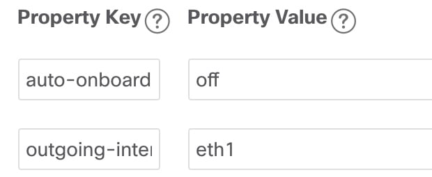
    • Provider Properties: Enter one of the following key/value pairs in the first set of fields:

      Property Key

      Value

      auto-onboard

      off

      Note

       
      Use this option if you plan to manually (via UI or CSV import) enter all of your network devices.

      When devices are discovered, the device data is recorded in the Cisco SR-PCE database, but is not registered in Cisco Crosswork Inventory Management database.

      auto-onboard

      unmanaged

      If this option is enabled, all devices that Cisco Crosswork discovers will be registered in the Cisco Crosswork Inventory Management database, with their configured state set to unmanaged. SNMP polling will be disabled for these devices, and no management IP information will be included. To get these devices into the managed state later, you will need to either edit them via the UI or export them to a CSV make modifications and then import the updated CSV. You can also assign credential profiles by adding them to the device CSV file before import (the credential profiles must already exist).

      auto-onboard

      managed

      If this option is enabled, all devices that Cisco SR-PCE discovers will be registered in the Cisco Crosswork Inventory Management database, with their configured state set to managed. SNMP polling will be enabled for these devices, and Cisco SR-PCE will also report the management IP address (TE Router ID for IPv4, or IPv6 Router ID for IPv6 deployment). The devices will be added with the credential profile associated with the device-profile key in the SR-PCE provider configuration.

      device-profile

      The name of a credential profile that contains SNMP credentials for all the new devices.

      Note


      This field is necessary only if auto-onboard is set to managed or unmanaged.

      outgoing-interface

      eth1

      Note


      You have to set this only if you want to enable Cisco Crosswork application access to SR-PCE via the data network interface when using the two NIC configuration.

      topology

      off or on.

      This is an optional property. If not specified, the default value is on.

      If value is specified as off, it means that L3 topology is not accessible for the SR-PCE provider.

      pce

      off or on.

      This is an optional property. If not specified, the default value is on.

      If value is specified as off, it means that LSPs and policies are not accessible for the SR-PCE provider.

      Figure 1. Provider Property Key and Value Example
      Provider Property Key and Value Example

      Note


      If managed or unmanaged options are set and you want to delete a device later, you must do one of the following:.

      • Reconfigure and remove the devices from the network before deleting the device from Cisco Crosswork. This avoids Cisco Crosswork from rediscovering and adding the device back.

      • Set auto-onboard to off, and then delete the device from Cisco Crosswork. However, doing so will not allow Cisco Crosswork to detect or auto-onboard any new devices in the network.

  2. Optional values:

    • Timeout: The amount of time (in seconds) to wait before timing out the connection to the SR-PCE server. The default is 30 seconds.

Step 4

When you have completed entries in all of the required fields, click Save to add the SR-PCE provider.

Step 5

Confirm that the SR-PCE provider shows a green Reachability status without any errors. You can also view the Events window (Administration > Events) to see if the provider has been configured correctly.

Step 6

Repeat this process for each SR-PCE provider.


Note


It is not recommended to modify auto-onboard options once set. If you need to modify them, do the following:

  1. Delete the provider and wait until deletion confirmation is displayed in the Events window.

  2. Re-add the provider with the updated auto-onboard option.

  3. Confirm the provider has been added with the correct auto-onboard option in the Events window.


What to do next

  • If you entered the auto-onboard/off pair, navigate to Device Management > Network Devices to add a devices.

  • If you opted to automatically onboard devices, navigate to Device Management > Network Devices to view the device list. To add more node information such as geographical location details, export the device list (.csv), update it, and import it back. If geographical location data is missing, you will only be able to see device topology using the logical map.

Return to the installation workflow: