Cisco Remote PHY Shelf 7200 Overview

Introduction

Driven by market evolution towards triple-play services, cable operators in emerging markets are seeking standardized solutions for economical and future proof access technologies. Much of the demand is driven by the need to provide higher bandwidth packet transport for Internet connectivity, video and voice services.

Data Over Cable Systems Interface Standard (DOCSIS®) is a standardized technology for services over cable and thus has strong interoperability between system providers. It also provides robust Quality of Service (QoS) methods, ensuring packet delivery during periods of network congestion.

The Cisco Remote PHY Shelf 7200 is designed to provide a dense, high availability DOCSIS upstream and downstream PHY solution. Cisco Remote PHY Shelf 7200 works in conjunction with a CCAP Core, such as a cBR-8 or cnBR, to create a distributed CMTS. The Cisco Remote PHY Shelf 7200 is fully interoperable with existing HFC infrastructure. The Cisco Remote PHY Shelf 7200 is fully DOCSIS 3.1 compliant.

Benefits

The Cisco Remote PHY Shelf 7200, in conjunction with a CCAP Core, or cnBR, implements a cost-effective, fully D3.1 compliant distributed CMTS solution.

  • Reduced investment cost including capital and operational expenditure.

  • Greater flexibility in mapping MAC thru-put to service groups.

  • CCAP Core or cnBR need not be co-located with HFC optics, reducing local power and space requirement.

  • No restriction on Converged Interconnect Network (CIN) network.

  • Future-proof architecture. Easy to migrate as the hardware and control functions are on separate layers.

  • End-to-end QoS assurance provided by DOCSIS.

  • Support for all DOCSIS services.

  • Support for existing DOCSIS network provisioning system.

  • High access bandwidth.

  • High availability.

Architecture Overview

Modular Headend Architecture version 2 (MHAv2) is a set of specifications for Remote-PHY solutions. The Cisco Remote PHY Shelf 7200 acts as the remote PHY system. On one side, the Cisco Remote PHY Shelf 7200 connects to a CCAP Core or V-CMTS via Ethernet. On the other side, it connects to an HFC network via co-ax.

Protocols that form this architecture include:

  • Downstream External PHY Interface Decapsulation—Downstream External PHY Interface (DEPI) is a L2TPv3-based protocol that is defined for downstream DOCSIS MAC management and data packets decapsulation. It is unidirectional, that is, from CMTS to Cisco Remote PHY Shelf 7200 system.

    DEPI supports:

    • IP/User Datagram Protocol (UDP).

    • DOCSIS MPT Mode (D-MPT)/Packet Streaming Protocol (PSP).

  • Upstream External PHY Interface Encapsulation—Upstream External PHY Interface (UEPI) is a L2TPv3-based protocol that is defined for upstream DOCSIS MAC management and data packets encapsulation. It is unidirectional, that is, from Cisco Remote PHY Shelf 7200 system to CMTS.

    UEPI:

    • Does not support UDP.

    • Supports PSP mode only.

    • Supports multiple pseudowires for RNG/BW-REQ/SPECTRUM-MGMT/MAP.

  • GCP—Generic Control Protocol, sets up a control plane tunnel over a generic transport protocol such as TCP or UDP. GCP is used to program the Cisco Remote PHY Shelf 7200 system upstream and downstream parameters from the CMTS. It is also used to control the Cisco Remote PHY Shelf 7200 system.

    GCP supports:

    • TCP/UDP

    • DS/US PHY configuration and CMC provisioning/configuration

    • Register mode and type, length, value (TLV) mode

    • Notification

Cisco Remote PHY Shelf 7200

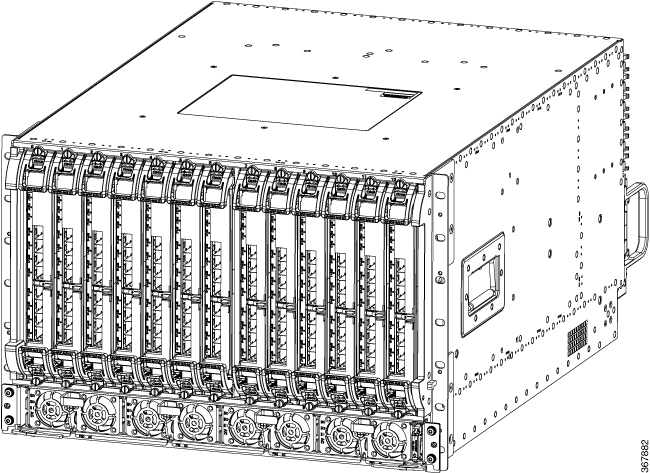
The Cisco Remote PHY Shelf 7200 is a 7 rack unit (RU) chassis. It supports 13 RPD modules and 6 RF PICs.

Figure 1. Cisco Remote PHY Shelf 7200

Below are some of the features of the Cisco Remote PHY Shelf 7200:

  • Full spectrum DOCSIS 3.0 support

  • Full spectrum DOCSIS 3.1 support

  • Converged broadcast, narrowcast, and VOD video support

  • Out of Band (OOB) signaling support

  • Eight 10 GBE SFP + backhaul connectivity (for each RPD line card), can be configured as 4+4 or 6+2 redundant model

  • CCAP support

For the Cisco Remote PHY Shelf 7200 described in this document is located at a Headend, Hub or VHUB (Virtual Hub). The output of the Cisco Remote PHY Shelf 7200 feeds a conventional HFC network with analog optical nodes and RF amplifier cascades. The Cisco Remote PHY Shelf 7200 is designed to connect to a CCAP Core or cnBR.

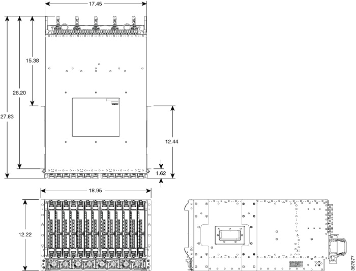
Figure 2. Cisco Cisco Remote PHY Shelf 7200 dimensions

The features of the Cisco Remote PHY Shelf 7200 are as follows:

Table 1. Cisco Remote PHY Shelf 7200 features

Feature

Feature Description

Functionality

  • 72 Service Groups (1x2 ratio)

  • 1 DS + 2 US per Service Group

  • 12+1 RF Redundancy

Chassis Size

  • 72 SG (1x2 ratio) 7RU, 19” Rack Mount Chassis (12.25” H x 17.45” W x 28.83” D)

  • 13 slots for RPD modules, 72 SG with 12+1 redundancy.

  • Front optics inputs and rear RF outputs

Power Supplies

  • Chassis facility power requirement – 4200 W

  • 2 + 2 redundancy for AC and DC applications

Environment

  • 0 to 40℃, -60 m to 3048 m (Normal Operation)

  • 0 to 50℃, -60 m to 4175 m (Extended Operation)

Simple Software Functions

Higher Availability

SUPless Design

The shelf has no supervisor card; rather one RPD, determined thru arbitration, will provide shelf manager functionality.

RPD Line Card (6x12)

  • CIN (Converged Interconnect Network) interface: 40G (1+1 redundant) using 8 SFP+ modules

  • RF interface: 6 DS x 12 US RF ports

  • Downstream DOCSIS

    • 6 downstream RF ports

    • Up to 160 QAM narrowcast channels per port

    • Up to 6 OFDM 192 MHz channels per port

  • Upstream DOCSIS

    • 12 upstream RF connectors

    • Up to 12 single-carrier QAM channels per port (5 MHz to 85 MHz)

    • Up to two 96 MHz OFDMA operations per port (5 MHz to 204 MHz)

PIC Cards (RF Switch)

Provide US/DS RF switching function between dedicated-protect and active RPD Line Card. Simplified to maximize the MTTF (Mean Time To Failure): no SW, firmware or programmable images; just solid state switches, amps and off the shelf I2C chips.

Power Shelf

  • Utilizes the same cBR8 AC and DC power supply modules

  • 4200W 2+2 redundant AC/DC Shelf with 4 PEMs

Fan Controller Card (FCC)

  • Hot swappable module

  • Five 80 mm fan modules capable of cooling entire shelf with one fan failure.

  • System can withstand the temporary fan shelf removal of one minute if fan shelf replacement is needed.

  • 13 port GE Managed Ethernet Switch [MES] providing inter-RPD connections and misc. system functions e.g. PIC cards control, FAN PWM (Pulse-Wide Modulation) control and more.

  • Fans can operate without active PWM control – defaults to open loop (fastest speed)

  • RPD shelf manager arbitration function

  • Must be present for system to bootup, but once up system can run without the card for limited replacement durations (High availability is not supported as MES is removed).

High Availability

SUPless design, any RPD Line Card (not dedicated protect) can be the shelf manager

No service interruption upon:

  • Working RPD Line Card failure – software or hardware

  • Switch back after software crashes

  • Replacing bad RPD Line Card

  • OIR of the working RPD Line Card

Consider the following points before getting started:

  • Service interruption is expected upon replacement of PIC card. Plan your work accordingly.

  • One designated slot for protect module, which can be used as a working slot.

Midplane based design

  • RPDs, PICs, Fan Control Card and integrated power shelf

  • Cable Once Capable: No re-cabling RF during RPD module replacement.

Front and Rear View

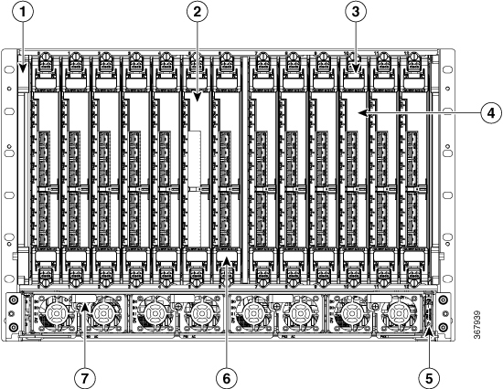
The following figure shows the front view of Cisco Remote PHY Shelf 7200.

Figure 3. Cisco Remote PHY Shelf 7200 Front View

1

Cisco Remote PHY Shelf 7200 Chassis

2

Cisco Remote PHY Shelf 7200 LC Blank

3

Cisco Remote PHY Shelf 7200 6X12 LC

4

Cisco Remote PHY Shelf 7200 Filter (RPD Air Filter Replacement)

5

System Power ON/OFF switch on the Cisco Remote PHY Shelf 7200-AC-SHLF or Cisco Remote PHY Shelf 7200-DC-SHLF

6

Slot 6 is designated as the redundant RPD

7

CBR-AC-PS

Or,

CBR-DC-PS

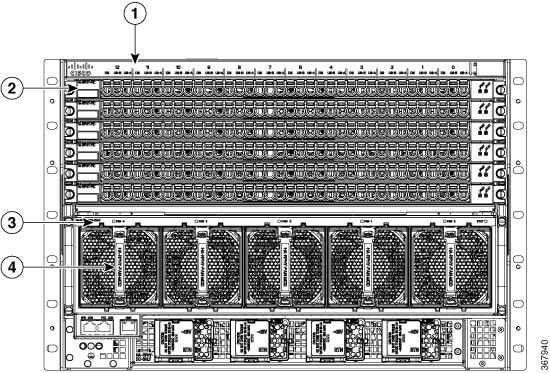
The following figure shows the rear view of Cisco Remote PHY Shelf 7200.

Figure 4. Cisco Remote PHY Shelf 7200 Rear View

1

Cisco Remote PHY Shelf 7200 Chassis

2

Cisco Remote PHY Shelf 7200 PIC

3

Cisco Remote PHY Shelf 7200 Fan Tray

4

Cisco Remote PHY Shelf 7200 Fan Module

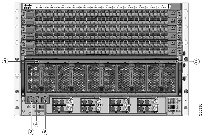
Figure 5. Cisco Remote PHY Shelf 7200 LED's and ports

1

Cisco Remote PHY Shelf 7200 Fan Status LED

2

Cisco Remote PHY Shelf 7200 Fan Control Card Status LED

3

Cisco Remote PHY Shelf 7200 RPD Console

4

Cisco Remote PHY Shelf 7200 Fan Control Card Console

5

Cisco Remote PHY Shelf 7200 1 Gbs Network Port

The chassis has a front-to-rear airflow. Five rear fans modules draw cooling air into the front RPD's in the chassis and across internal components to maintain an acceptable operating temperature. The fans are numbered from 0 to 4, right to left. The fans are hot-swapable.

Four power supplies (AC or DC) are accessed from the front of the chassis and are hot-swappable.

Physical Characteristics

Be familiar with the physical characteristics of the Cisco Remote PHY Shelf 7200 Device Shelf to assist you in placing the system at a proper location.

The following table shows the weight and dimensions of the Cisco Remote PHY Shelf 7200 Device Shelf:

Table 2. Physical Characteristics of the Cisco Remote PHY Shelf 7200

Characteristic

Cisco Cisco Remote PHY Shelf 7200 Device Shelf

Height

12.25 in. (31.12 cm) - 7RU

Width

  • 17.45 in. (44.32 cm) without rack mounts, or mounts reversed

  • 17.65 in. (44.83 cm) with front rack mounts

Depth

  • 27.83 in. (70.69 cm) overall excluding cables

  • 26.20 in. (66.55cm) from front rack mount excluding cables

Weight

271 lbs (123 kg) Maximum Capacity

Airflow

Front-to-back

Power Shelf

The Cisco Remote PHY Shelf 7200 supports AC or DC power supply options. The modular chassis configurations support the installation of four power supplies for 2+2 redundancy, the current sharing feature is supported when two or more power suppliers are installed in the system. When a power supply module fails, or is removed, the other power supply provides power requirements for the chassis. This allows you to hot-swap the power supply modules without impacting the functionality of the system.


Caution

Cisco Remote PHY Shelf 7200 system can support up to four power supply modules, 2+2 redundant. Mixed AC and DC power supply units are not supported in the same chassis and the slots are keyed for AC or DC only depending on the configuration.


The Power Shelves provide the power conversion, filtering, and conditioning from facility input power to the required -54 V midplane power that is used within the chassis. Both AC and DC Power Shelves are available depending on the facility input voltage. These modules have internal fans for cooling.

The Power Shelves are installed in the front of the chassis.

Power System

The Cisco Remote PHY Shelf 7200 Solution chassis is powered using AC or DC power inputs.

The Cisco Remote PHY Shelf 7200 power system supports:

  • 2+2 redundancy for the DC power systems and AC power systems

  • Online Insertion and Removal (OIR)

Redundancy

  • For the DC-powered Cisco Remote PHY Shelf 7200 with 2+2 redundancy, the chassis must have at least two operational DC Power Modules to be functional.

  • For the AC-powered Cisco Remote PHY Shelf 7200 with 2+2 redundancy, the chassis must have at least two operational AC Power Modules to be functional.

The physcial spcifications of the AC and DC shelves are as follows:

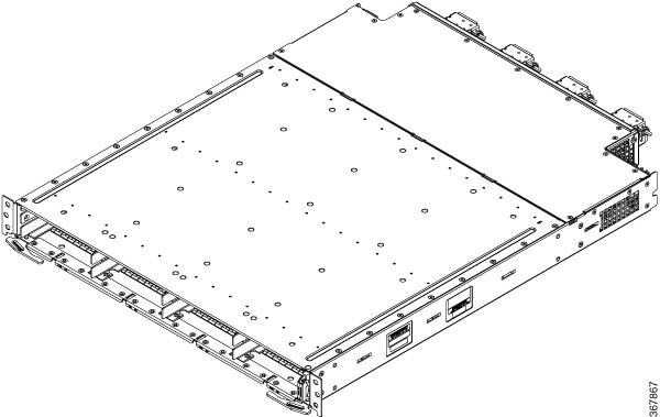
Figure 6. AC Power Shelf
Table 3. Physical Specifications of the AC Power Shelf

Unit

Dimensions

Width

18.59 in (47.21cm)

Height

1.94 in (4.92cm)

Depth

23.72 in (60.24cm)

Weight

14.7 lb (6.67 Kg)

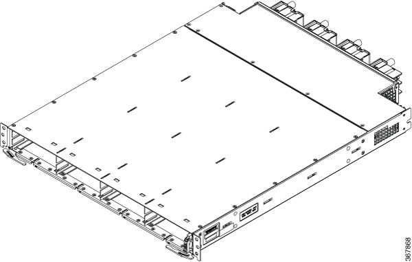
Figure 7. DC Power Shelf
Table 4. Physical Specifications of the DC Power Shelf

Unit

Dimensions

Width

18.59 in (47.21cm)

Height

1.94 in (4.92cm)

Depth

23.72 in (60.24cm)

Weight

15.1 lb (6.85 Kg)

Power Supply LEDs

Both AC and DC Power Modules have the following LEDs:

  • Input power LED—Power input status LED

  • Output power LED—Power output status LED

  • Fault LED—Fault status LED

The following table describes the power supply LEDs.

Table 5. Power Module LEDs

Function Label

Color

Description

Default State

Input OK

Green

Green when input power is ok, off otherwise. Set by module logic.

Off

Output OK

Green

Green when output power is ok, off otherwise. Set by module logic.

Off

Fault

Red

Red when fault occurs, off otherwise. Set by module logic.

Off

Power Supply Fans

The fans in the power supply module are used for cooling the power supply module. The system-level cooling is provided by fans within the chassis. The power supplies do not depend on the system-level fans for cooling. Fan failure is determined by fan-rotation sensors.


Note

The fans in the power supply modules will run when the power supply is plugged in, and even when the chassis power switch is turned-off.


Power Cords

The following table lists the supported power cords.

Power Cord Item Number

Description

PWR-CAB-AC-BLK

Power Cord, 20A, C20-C21, BLK

PWR-CAB-AC-ARG

Power Cord for AC Power Module - Argentina, 10A, 250V, 2500mm, -40°C to +85°C

PWR-CAB-AC-AUS

Power Cord for AC V2 Power Module Australia, 10A, 250V, 2500mm, -40°C to +85°C

PWR-CAB-AC-BRA

Power Cord for AC V2 Power Module - Brazil, 10A, 250V, 2500mm, -40°C to +85°C

PWR-CAB-AC-CHN

Power Cord for AC V2 Power Module - China, 10A, 250V, 2500mm, -40°C to +85°C

PWR-CAB-AC-EU

Power Cord for AC V2 Power Module - Europe, 16/10A, 250V, 2500mm, -40°C to +85°C

PWR-CAB-AC-ISRL

Power Cord for AC V2 Power Module - Israel, 16/10A, 250V, 2500mm, -40°C to +85°C

PWR-CAB-AC-ITA

Power Cord for AC V2 Power Module - Italy, 10A, 250V, 2500mm, -40°C to +85°C

PWR-CAB-AC-SUI

Power Cord for AC V2 Power Module - Swiss, 10A, 250V, 2500mm, -40°C to +85°C

PWR-CAB-AC-UK

Power Cord for AC V2 Power Module - UK, 13/10A, 250V, 2500mm, -40°C to +85°C

PWR-CAB-AC-USA

Power Cord for AC V2 Power Module - USA, 20A, 250V, 2500mm, -40°C to +85°C

PWR-CAB-AC-JPN

Power Cord for AC V2 Power Module - Japan

PWR-CAB-AC-SA

Power Cord for AC V2 Power Module - South Africa

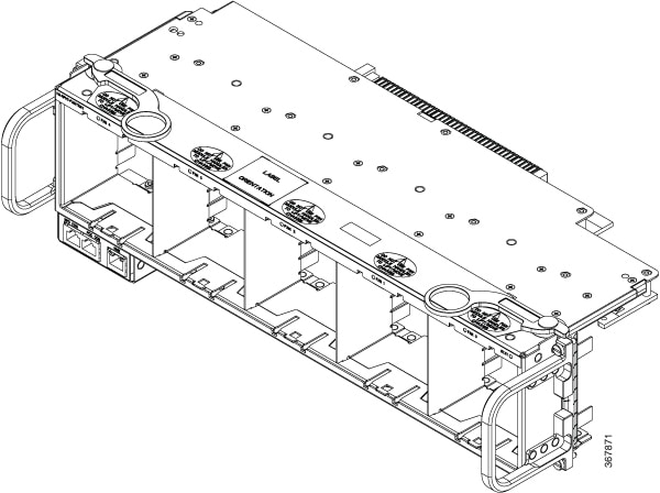
Fan Tray

The Fan Tray is installed at the rear of the Cisco Remote PHY Shelf 7200 and is comprised of the Fan Control Card and associated support enclosure for installation of five fan modules for system level cooling. The fan bays are numbered from 0 to 4 (right to left).

Figure 8. An empty Fan Tray

The faceplate of the Fan Tray has the following LEDs:

Table 6. Fan Tray LEDs:

Function Label

Color

Description

Default State

Fan 0-4

Green

Fan is running ok.

Off

Yellow

Fan is not running ok.

Off

Status

Green

FCC is up and running (Nemo watchdog is touched).

Off

Yellow

FCC has detected a fault. Watchdog has timed out setting LED or software crashed with core-dump and sets the LED.

Off

Table 7. Physical Specifications of the Fan Tray (Empty)

Unit

Dimensions

Width

17.45 in (44.32cm)

Height

4.98 in (12.64cm)

Depth

8.38 in (21.28cm)

Weight

5.9 lb (2.68 Kg)

Fan Module

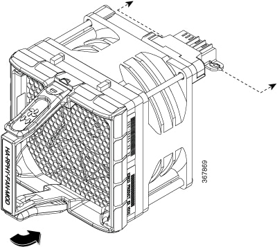
The Cisco Remote PHY Shelf 7200 has five modular Fan Modules installed in the rear Fan Tray to supply cooling air to the system. The bays are numbered from 0 to 4.

The following image shows a Fan Module.

Figure 9. Fan Module
Table 8. Physical Specifications of the Fan Module

Unit

Dimensions

Width

3.38 in (8.58cm)

Height

3.38 in (8.58cm)

Depth

5.14 in (13.05cm)

Weight

0.625 lb (0.28 Kg)

Each Fan Module is comprised of a fan, a handle support structure, EMI containment, and the interface connector to the FCC card. The fans in each module operate at variable speeds as set by the FCC based on inlet air temperature to the system after bootup. Fan speed during bootup are fixed to a default RPM value until the system has properly booted up and the RPDs are able provide temperature data. The multi-Fan Module cooling architecture permits one fan failure or removal at any time during normal operational conditions. All the remaining fans are capable of changing to full speed operation to compensate for the failed fan module.


Warning

When the Fan Tray is OIR’d all the Fan Module are removed with it which results in a total loss of cooling air to the system. If a Fan Tray is removed, replace it with a functioning Fan Tray within one minute of the removal in order to avoid critical thermal alarms relating to overheating of individual components.

Shelf Manager

Every RPD in a Cisco Remote PHY Shelf 7200 runs a Shelf Manager service on its local CPU. Each Shelf Manager provides services including software upgrade, configuration download, and status monitor.

A Master Shelf Manager is elected among all RPDs in an arbitration process that is facilitated by the Fan Control Card (FCC) that is located in the Fan Tray. The Master Shelf Manager is responsible for all Shelf communication with external devices, as well as interaction with Fan Control Card. The FCC keeps a coherent copy of each RPDs Shelf Manager state at all times.

Keep alive messages are passed between RPD Shelf Managers through EOBC (Ethernet Out-Of-Band Communications). If an RPD goes offline, the other RPDs will be made aware of this by the absence of these periodic keep alive messages. If the RPD hosting the Master Shelf manager goes offline, a new Master Shelf Manager will be elected among the remaining Shelf Managers.

The Master Shelf Manager election protocol essentially promotes the RPD with the lowest IP address to Master Shelf Manager status. This election process is dependent on EOBC via the Fan Control Card.

When an RPD is inserted, the Shelf Manager on the newly installed RPD will detect the system elected Master Shelf Manager by monitoring keep alive messages from master Shelf Manager. If there is no existing Master Shelf Manager on chassis, this new inserted Shelf RPD Shelf Manager will be the Master Shelf Manager.

All RPDs monitor the presence of the Fan Control Card through a dedicated presence pin. If the Fan Control Card is removed, all RPDs will be aware of this event. In this situation, IPC connections between Shelf Managers will fail and each RPD will continue to operate independently. LCHA failover is not supported in this condition.

The following functions need to be met for the Shelf Manager:

  • Keep alive: After IPC communication between shelf line cards and Fan Control Card setup, there will be keep alive messages between shelf managers, and keep alive between master shelf manager and Fan Control Card manager. This keep alive message is software process level message used to tracking IPC connections between shelf line cards and Fan Control Card. It also used for master shelf manager role notification. If keep alive messages between master shelf manager to shelf managers are lost, master shelf manager election function will be executed and a new master shelf line card manager will be elected.

  • Software upgrade: There are two methods for a software upgrade. One is through CLI, another is through SSD. For CLI upgrading, only the Master Shelf Manager located on the Shelf Line Card CLI will accept software upgrade operation. Upgrade operations on other Shelf Line Card CLI will be redirected to the Master Shelf Manager located shelf line card CLI. Master shelf manager will get the bundle image from CCAP or server side depend on configuration, then dispatch the bundle image to Fan Control Card. The Fan Control Card will power off the shelf line cards and reload self to achieve software upgrade operation.

  • Status collection: Master Shelf Manager collects the status information on all Shelf Line Cards, RPDs and Fan Control Cards.

  • Reload shelf line cards: After the Master Shelf Manager receives the reload command from CLI, the Master Shelf Manager will send IPC to all cards including the Fan Control Card. The Fan Control Card will reload all cards after 30 seconds.

  • Configuration download: The shelf chassis-related configuration is stored on each shelf line card. The Master Shelf Line Card will collect Shelf Line Cards configuration and Fan Control Card related settings. Every time the Shelf Line Card has a configuration change, it will trigger the Shelf Manager by sending IPC to the Master Shelf Manager to do the configuration sync, and the configuration will send a copy to Fan Control Card through Master Shelf Manager.
Digital Midplane

The Digital Midplane provides connections between the RPDs, Fan Control Card, PICs and the Power Shelf cable harness. It also provides the -54V and 5V AUX voltage distribution. Unlike other cable chassis, there is no ACT2 on the Midplane storing MAC addresses. The Midplanes highest signal rate is just 1Gbps, and no RF goes through the Digital Midplane.

RPD

The Remote PHY Device (RPD) is a DOCSIS 3.1 PHY with logic allowing it to operate remotely from the MAC. RPD controls the power, clock, data-plane, control, and the dejitter buffer.

The Cisco Remote PHY Shelf 7200 Line Card has the following features:

  • Compliance to DOCSIS 3.1 specification

  • 12 US RF ports

    • US Frequency Range 5 MHz – 204 MHz

    • Support up to 12 ATDMA /8 ATDMA+4 SCDMA per port

    • Support up to 2 OFDMA (96 MHz) Receivers per port

    • Spectrum management (FFT)

  • 6 DS RF ports

    • DS Frequency Range: 54 MHz - 1.218 GHz

    • 160 QAM per port

    • 6 OFDM min 24 MHz and max 192 MHz channel width per port

    • RF Monitoring: D3.0 Tuner/demod with RF power, MER, BER report

    • DOCSIS/Video de-jitter buffer (20 ms (+/-10 ms) at 60 Gbps)

The RPD Data-plane provides a connection between the WAN side 10Gbs Ethernet and the HFC side RF ports.

Up to 40 Gbps of DS data enters through four of the SFP+ modules. The remaining four modules provide 1+1 redundancy. Their output is R-DEPI Ethernet packets which are forwarded to a de-jitter FPGA, providing buffering and rate shaping of video stream packets.

The R-DEPI packets are sent to the DS PHY chip which preforms interleaving, FEC, symbol mapping, RF modulation and upconversion. Finally, the DS RF is amplified and filtered by the DS RF block at which point it exits the RPD to the RF PIC. For the US path, the RF enters the card from the PIC and is then filtered and amplified by the US RF circuitry. It is then demodulated by the PHY chip and converted to R-UEPI packets. These packets are sent to the dejitter buffer providing buffering for the SFP+ interfaces. Finally, the four active SFP+ transmit the packets to the remote MAC across the network.

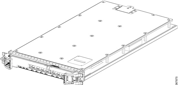
The following image shows an RPD.

Figure 10. RPD
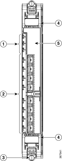
Figure 11. RPD Front view

1

Status LED's

2

8x SFP + Ports

3

Captive Screws

4

Ejector

5

Field Replaceable Air Filter (HA-RPHY-FILTER)

The following table provides information on the RPD LED's.

Table 9. RPD Section LED’s

Nomenclature

Color

Indication

STAT-Status

Off

U-boot corrupted or no power.

Blinking green

U-boot is booting kernel.

Solid green

Card is operational.

Blinking yellow

Card is in U-boot.

Solid yellow

Card is up, but HA fault has been detected.

PROT-Protect

Off

Line card is not a protection card, or no power.

Solid green

Line card is a protection card, and is actively protecting (passing live traffic).

Solid blue

Line card is a protection card, and the card is standing by to protect.

RPLC-Replace

Off

Line card does not require replacement.

Solid white

Line card requires replacement.

SFP+ 0~7

Off

Link not up & SFP + module present or no power.

Solid green

10G link is up

Solid yellow

No SFP + module present

PIC

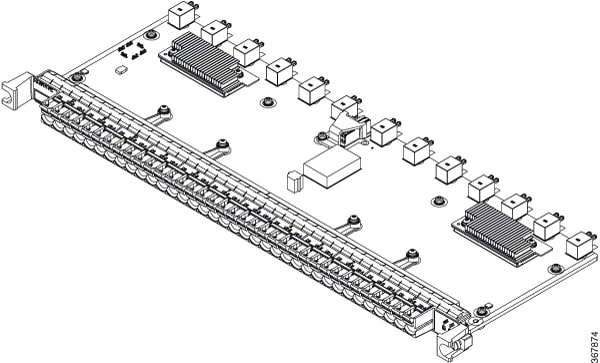
The PIC card uses solid-state switch to create a switching path between the dedicated protect RPD in slot 6 and the 12 other RPDs in the Cisco Remote PHY Shelf 7200 chassis. This is for US and DS. The switching path is configured by the shelf as part of the HA process. For example, a failure of RPD_4 would cause the Shelf Manager to configure the PIC switches to replace its RF I/O with that from the dedicated protect RPD. The PIC also has hardware to help check RF signal path integrity by both monitoring the DS and inserting an RF test signal on the US.

The PIC has a single point of failure. To maximize the MTTF of the PIC, it must be kept as simple as possible. The Cisco Remote PHY Shelf 7200 PIC uses solid-state switches in place of the mechanical relays used on previous generation PICs. Also, it does not have any programmable devices nor CPUs, but rather simple I2C I/O expanders. The new PIC has no firmware images to support.

Figure 12. Cisco Remote PHY Shelf 7200 PIC
Table 10. Physical Specifications of the PIC

Unit

Dimensions

Width

17.36 in (44.09cm)

Height

0.82 in (2.08cm)

Depth

6.56 in (16.66cm)

Weight

3.1 lb (1.41 Kg)

The features of the Cisco Remote PHY Shelf 7200 PIC are:

  • Surge protector

  • Demodulator

  • Power meter

  • US test signal

  • Solid-state switches 2:1, 6:1

  • DS RF amp for better return loss matching

  • MES in control of all PIC functions through I2C control

  • Simplified power design and power sequencer

  • DS at MCX connector meets the DOCSIS 3.1 RF specification

  • ACT2 PID

  • FLASH holding calibration data

  • No firmware upgradeable images

  • US and DS ports accept 75 Ohm compression type MCX connectors

Table 11. PIC Section LED’s

Function Label

Color

Description

Default State

Status

Green

Board is operating normally, no faults detected.

Off

Status

Amber

Card is up, but fault has been detected.

Off

Protect

Blue

Card is in Protect (failover) mode whereby the RF from the protect RPD is connected to the cable plant.

Off

PIC RF connections connect directly to the RPDs. The digital connections come from the MES through the Digital Midplane.

Air Filter

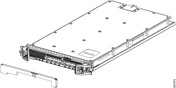
The Air Filter is a field replaceable unit on the Line Cards. It removes dust in the air that is drawn into the router by the cooling fans. We recommend that you examine the air filter at least once a month, or more frequently if required. Do not clean and re-use the Air Filters. They must be replaced when they are clogged or worn out.

Figure 13. Air Filter

Note

You can remove and install an Air Filter (HA-RPHY-FILTER) when the Cisco Remote PHY Shelf 7200 is powered-on and working. The air filters are located on the front of each RPD module.


NEBS Level 3 Compliance

The Cisco Remote PHY Shelf 7200 is designed to meet Network Equipment Building System (NEBS) Level 3 compliance.

How and What to Order

Table 12. Ordering Information for Cisco Remote PHY Shelf 7200 Router

Part Number

Product Description

HA-RPHY

Container PID for configuring the Cisco Remote PHY Shelf 7200

HA-RPHY-6X12-LC

RPD Line Card for Cisco Remote PHY Shelf 7200

HA-RPHY-CHASSIS

Cisco Remote PHY Shelf 7200 Chassis

HA-RPHY-FAN-MOD

Fan Module for Cisco Remote PHY Shelf 7200

HA-RPHY-FAN-TRAY

Fan Tray

HA-RPHY-PIC

RF-PIC for Cisco Remote PHY Shelf 7200 RPD Line card

HA-RPHY-FILTER

Air Filter for the Cisco Remote PHY Shelf 7200

HA-RPHY-AC-SHLF

AC Power Shelf for Cisco Remote PHY Shelf 7200

HA-RPHY-DC-SHLF

DC Power Shelf for Cisco Remote PHY Shelf 7200

HA-RPHY-LC-BLANK

RPD Line Card Blank for Cisco Remote PHY Shelf 7200

CBR-AC-PS

Cisco Remote PHY Shelf 7200 AC Power Supply

CBR-DC-PS

Cisco Remote PHY Shelf 7200 DC Power Supply

HA-RPHY-CBLMG-KIT

Rear cable management kit for Cisco Remote PHY Shelf 7200

HA-RPHY-OCMG-KIT

Front optical cable management kit for Cisco Remote PHY Shelf 7200

HA-RPHY-PS-BLANK

Power supply blank for Cisco Remote PHY Shelf 7200

HA-RPHY-ACC-KIT

Accessory kit for Cisco Remote PHY Shelf 7200

HA-RPHY-CABLE-RF

RF cable kit for one RPD of the Cisco Remote PHY Shelf 7200

How to Order

To place an order, visit the Cisco Ordering Home Page.