Installing the Chassis
The Cisco Remote PHY Shelf 7200 can be either mounted on the rack at the front or in the middle. Also, the router can be either mounted on a standard 19-inch wide four-post equipment rack unit or a two-post rack unit.
 Note |
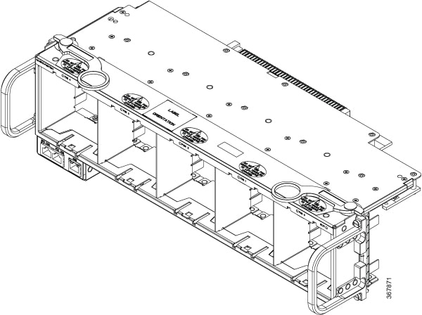
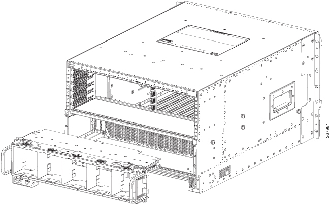
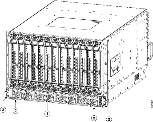
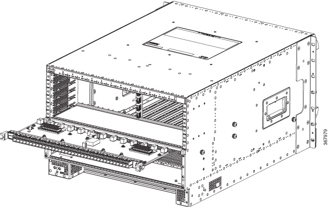
The Cisco Remote PHY Shelf 7200 fully configured system can weigh up to 271 lbs, components must be removed from the chassis to make the chassis lighter for rack installation. Remove all front power modules and front RPD cards for rack mounting to reduce the weight. The PIC cards and Fan Tray can remain in the system during rack mounting. For instructions on how to remove the components, see the monitoring sections. Make sure that you place the cards and modules in an anti-static bag until you install the chassis in the rack. Proceed with the installation if you have already unpacked your chassis and read all the site requirements for your new equipment. Required Tools and Equipment
|
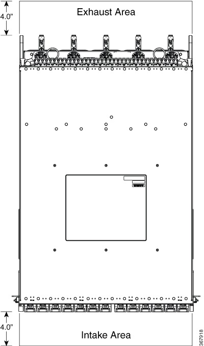
Verifying Rack Dimensions
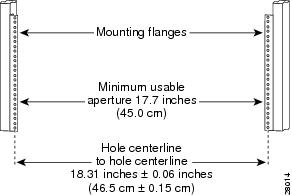
Before you install the chassis, measure the space between the vertical mounting flanges (rails) on your equipment rack to verify that the rack conforms to the measurements shown in the following figure.
Procedure
| Step 1 |
Mark and measure the distance between two holes on the left and right mounting rails. The distance should measure 18.31 inches ± 0.06 inches (46.5 cm ± 0.15 cm).
|
||
| Step 2 |
Measure the space between the inner edges of the left front and right front mounting flanges on the equipment rack. The space must be at least 17.7 inches (45 cm) to accommodate the chassis. |
Installing the Chassis Installation Brackets
Each chassis is shipped with two chassis installation brackets in the accessory kit. These brackets aid in installing a chassis into a 19-inch rack. These brackets are used as a support base to vertically position and set the chassis before installing the rack mount screws.
Procedure
| Step 1 |
Determine the position in the rack where you want to mount the chassis. If you are mounting more than one chassis in the rack, start from the bottom or the center of the rack. Hold the chassis installation bracket, where the bottom of the chassis will be positioned vertically in the rack. |
||||
| Step 2 |
Secure the chassis installation bracket to the front rails with rack-mount screws. If a second internal rack rail is present which is not more than 23 inches from the front rail, position the second installation bracket to create a rear support for the chassis during installation. 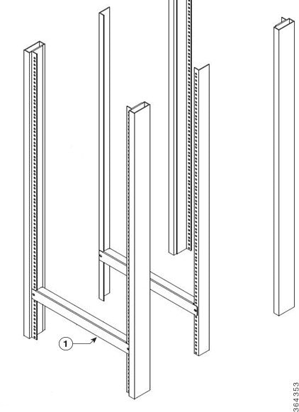
|
Attaching the Chassis Rack-Mount Brackets
The chassis is shipped with the rack mount brackets pre-installed in the front position. The rack mount brackets can be removed and reversed in the mid-mounting location on the chassis.
Note |
After you install the chassis in the rack, the rear RF cable-management brackets can be installed on the chassis. |
Attach the rack-mounting brackets either in the front or the middle of the chassis.
-
Front Rack-Mounting the system: The chassis is shipped with the rack-mount brackets installed in the front. Proceed to Installing the Cisco Remote PHY Shelf 7200 in a Rack.
-
Mid Rack-Mounting the system: Install the mounting bracket in the middle of the chassis, so that you can recess the chassis in the rack or install the chassis in a two-post rack unit.
To install the rack-mount brackets in the middle of the chassis, complete the following steps:
Before you begin
Required Tools and Equipment
-
#2 Phillips torque screwdriver
Procedure
| Step 1 |
Remove the rack-mount brackets installed in the front of the chassis by unscrewing the M5 undercut flat-head screws using a #2 Phillips screwdriver. |
||
| Step 2 |
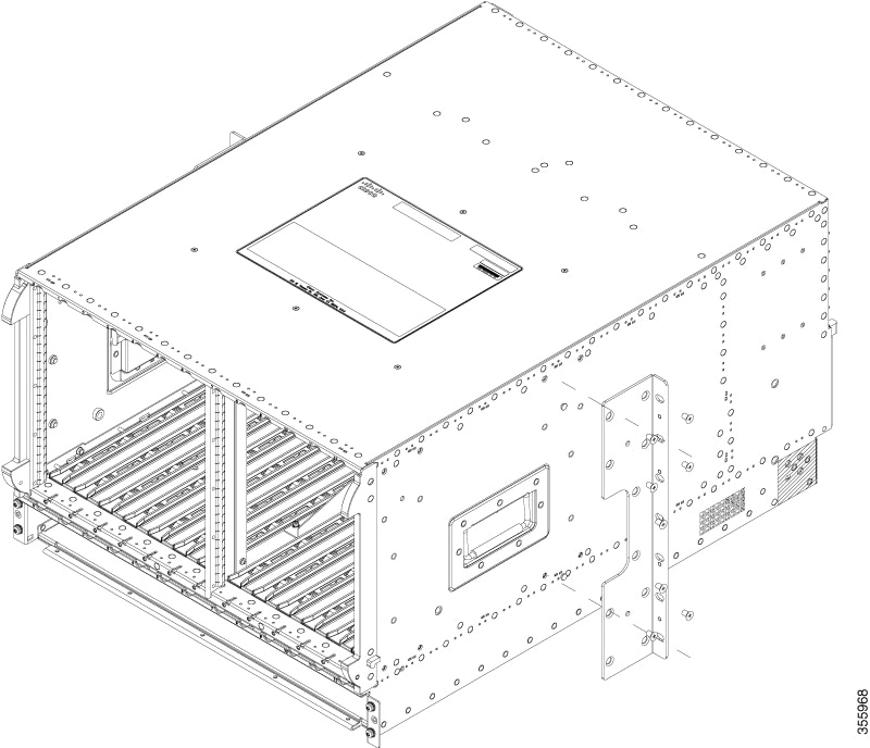
Locate the threaded holes at the middle on the side of the chassis that align with the holes in the rack-mount bracket. 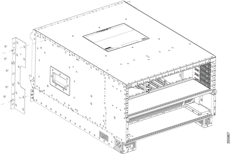 |
||
| Step 3 |
Install the 8 M5 undercut flat-head screws to secure each rack-mounting bracket to the chassis.
 |
||
| Step 4 |
Repeat the steps 1, 2, and 3 on the other side of the chassis. |
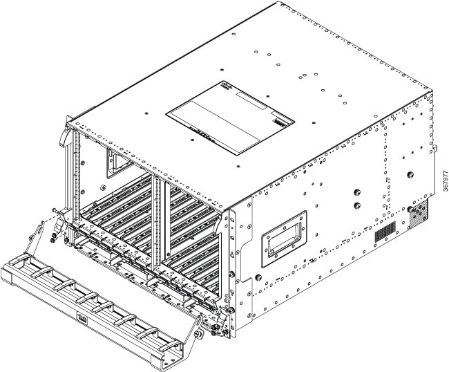
Installing the Cisco Remote PHY Shelf 7200 in a Rack
You can install the chassis in either a four-post rack unit or a two-post rack unit.
Before you begin
-
Verify rack dimensions.
-
Install chassis installation brackets.
-
Attach the chassis rack-mount brackets.
 Warning |
To prevent physical injury when mounting or servicing this unit in a rack, you must take special precautions to ensure that the system remains stable. The following guidelines are provided to ensure your safety:
|
Procedure
| Command or Action | Purpose |
|---|---|
|
Rack mount the chassis by securing the rack-mount brackets to two posts or mounting strips in the rack. |
Use at least four rack-mount screws on each side to fasten the two rack-mount brackets to the rack posts because the rack-mount brackets support the weight of the entire chassis. |
Installing the Cisco Remote PHY Shelf 7200 in a Four-Post Rack
Procedure
| Step 1 |
Ensure that all screw-fasteners on the installed components are securely tightened on the chassis. It is recommended to remove the front Power Supplies and RPD’s to lighten the chassis weight prior to installation. |
||
| Step 2 |
Ensure that your path to the rack is unobstructed. If the rack is on wheels, ensure that the brakes are engaged or the rack is stabilized. |
||
| Step 3 |
With two or more people, lift the chassis (partially unloaded) into position between the rack posts and rest it on the chassis installation bracket.
|
||
| Step 4 |
After the rear weight of the chassis is resting on the installation bracket, one person can hold it in place when the second person moves to the rear of the rack to slide it into place and hold the weight while the rack mount screws are tightened. 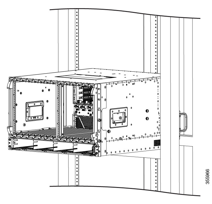 |
||
| Step 5 |
Position the chassis until the rack-mounting flanges are flush against the mounting rails on the rack. 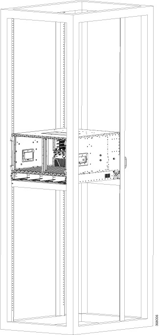 |
||
| Step 6 |
Hold the chassis in position against the mounting rails and do the following: |
What to do next
-
If necessary, remove the chassis installation brackets after ensuring that all screws are tightly secured to the rack unit.
Installing the Cisco Remote PHY Shelf 7200 in a Two-Post Rack
You can install the Cisco Remote PHY Shelf 7200 in a two-post 19-inch (48.26 cm) rack either as a front mount or a mid-mount if the spacing between rails is at least 17.70 inches (44.96cm) wide. If the rack rail opening is narrower than this you can only use the mid mount option for mounting the chassis into the two post rack.
The procedure for front mounting a chassis in a two-post rack is similar to the procedure for front mounting in a four-post rack, except that you cannot use the second chassis installation bracket.
 Caution |
If you are using a two-post rack, secure the rack to the floor surface to prevent tipping and physical injury, and avoid damage to the component. |
To mid-mount the chassis, follow these steps:
Procedure
| Step 1 |
Ensure that all screw-fasteners on the installed components are securely tightened on the chassis. It is recommended to remove the front Power Supplies and RPD’s to lighten the chassis weight prior to installation. |
||
| Step 2 |
Ensure that your path to the rack is unobstructed. If the rack is on wheels, ensure that the brakes are engaged or the rack is otherwise stabilized. |
||
| Step 3 |
Install the chassis installation bracket into the rack to support the chassis during installation when you secure it to the rack. |
||
| Step 4 |
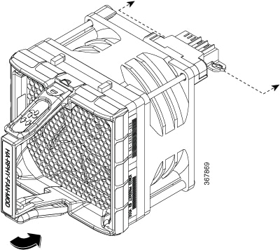
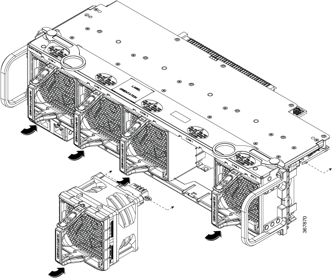
With two or more people, lift the chassis (partially unloaded) into position between the rack posts and rest it on the chassis installation bracket. The chassis can be lifted using the two large side handles and the rear Fan Tray Handles.
|
||
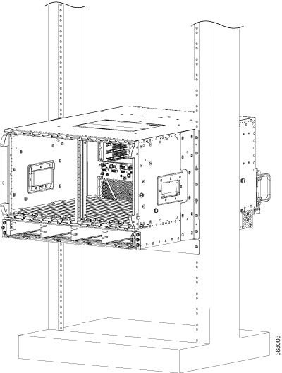
| Step 5 |
After the rear weight of the chassis is resting on the installation bracket, one person can hold it in place while the second person moves to the rear of the rack to help slide it into place and hold the weight while the rack mount screws are tightened. |
||
| Step 6 |
Position the chassis until the rack-mounting flanges are flush against the mounting rails on the rack. 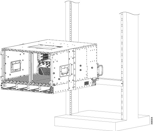 |
||
| Step 7 |
Hold the chassis in position against the mounting rails and do the following:
 |
||
| Step 8 |
Ensure that all screws on each of the side rack-mount brackets are tightened to the equipment rack before the chassis installation bracket is removed from the rack. |
What to do next
Attaching the Cable-Management Bracket
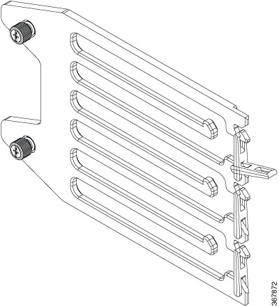
Note |
The chassis will not fit through a 19-inch rack rail opening with the cable management system pre-installed. |
Complete the following steps to install the Cable-Management Bracket:
-
Install the chassis into the rack.
-
Align the RF left side RF cable management to a set of holes on the side of the chassis. There are three mounting positions on the chassis depending on the number of cables that are required to be supported.
-
Secure the left side RF cable management using the thumb screws on the bracket.
-
Repeat steps 1-3 for the right side RF management bracket.
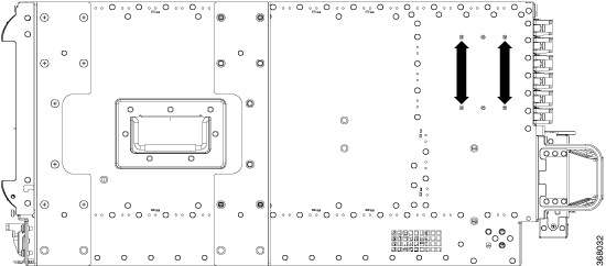
The Cisco Remote PHY Shelf 7200 has 216 ports, and the coax cable routing was designed for half the cables that are routed to either side of the system.
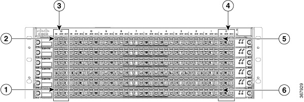
|
1 |
Slot12/DS5 |
2 |
Slot12/DS0 |
|
3 |
Slot 12 |
4 |
Slot 0 |
|
5 |
Slot0/DS0 |
6 |
Slot0/DS5 |
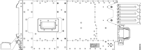
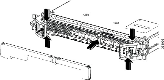
After routing the RF cables through the cable management, latches can be closed for retention of the cables. See the following image.
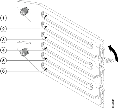
|
1 |
Cables from PIC0 |
2 |
Cables from PIC1 |
|
3 |
Cables from PIC2 |
4 |
Cables from PIC3 |
|
5 |
Cables from PIC4 |
6 |
Cables from PIC5 |
Attaching a Chassis Ground Connection
Before you begin
Warning |
This equipment must be grounded. Never defeat the ground conductor or operate the equipment in the absence of a suitably installed ground conductor. Contact the appropriate electrical inspection authority or an electrician if you are uncertain that suitable grounding is available. Statement 1024 |
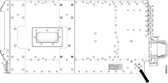
Before you connect the power or turn on the power to the chassis, you must provide an adequate chassis ground (earth) connection for the chassis. A chassis ground connector is available at the rear, left side of each Cisco Remote PHY Shelf 7200 chassis.
Caution |
The grounding wire is always the first to be installed or connected and the last to be removed or disconnected. |
Required Tools and Equipment
-
Phillips Screwdriver
-
¼-20 Phillips pan head with a square cone lock washer (available in the accessory kit)
-
2 hole 4-AWG dual crimp compression lug (available in the accessory kit)
-
4 or 2 AWG grounding wire—The ground wire and lug must be always as large as the input gauge. For example, to use 2 AWG for the DC inputs, the ground lug and wire must be 2 AWG or bigger.
-
Crimping tool for the ground lug
Procedure
| Step 1 |
Use the wire stripper to strip one end of the AWG #4 wire approximately 1.12 inches (28.4 mm). |
||
| Step 2 |
Insert the AWG #4 wire into the wire receptacle on the grounding lug. |
||
| Step 3 |
Use the crimping tool to carefully crimp the wire receptacle around the wire; this step is required to ensure a proper mechanical connection. |
||
| Step 4 |
Locate the chassis ground area on the rear lower left-side panel of your chassis. |
||
| Step 5 |
Insert the two ¼-20 screws (available in the accessory kit) through the holes in the grounding lug, and tighten until the grounding lug is held firmly to the chassis.
|
||
| Step 6 |
Connect the opposite end of the grounding wire to the appropriate grounding point at your site to ensure an adequate chassis ground. |
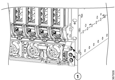
Installing the Optical Cable Management Kit (Optional)
To install the optional Optical Cable Management (OCMG) Kit, complete the following steps:
-
Remove the top two screws from the power shelf flange ears. Keep the screws safe.
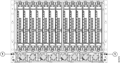
1
T15 Drive Screws
-
Align the Optical Cable Management Kit to the chassis.
-
Install the right and left cable management support brackets onto the power shelf flanges as shown in the following image. Secure the bracket with four T15 Torx screws. Tighten to 6-8 Lb-In torque.
1
T15 Drive Screws
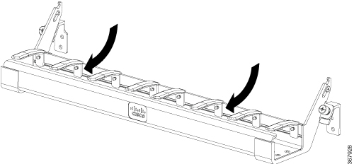
-
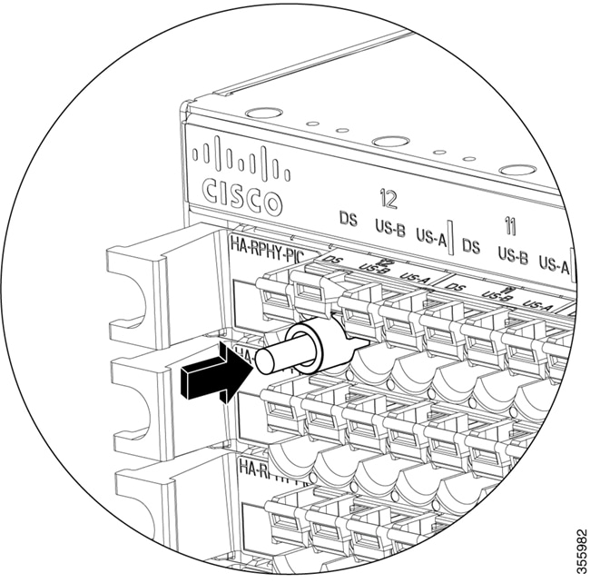
Install the shoulder screws through the cable management tray slots and into the chassis side bezel threaded holes. Secure the shoulder screw using a T10 Torx screwdriver, tighten to 5-6 Lb-In torque.
Figure 5. 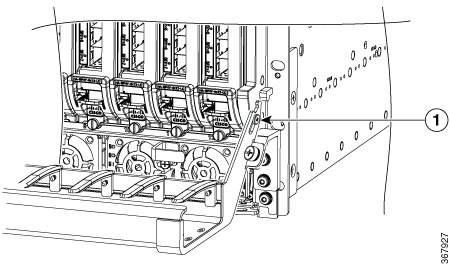
1
Shoulder Screw
-
Orient the cable tray and secure the two captive screws to the support brackets by hand.

 Feedback