- Cable Modem Upstream RF Adaptation
- Configuring Downstream Cable Interface Features on the Cisco CMTS Routers
- Configuring Upstream Cable Interface Features on the Cisco CMTS Routers
- Cable Modem Steering on the Cisco CMTS Routers
- DOCSIS 2.0 A-TDMA Modulation Profiles for the Cisco CMTS Routers
- DOCSIS 3.0 Downstream Bonding for Bronze Certification
- Downstream Channel ID Assignment on the Cisco CMTS Routers
- Downstream Resiliency Bonding Group
- IGMP-Triggered Dynamic Channel Change Load Balancing for DOCSIS 2.0 Cable Modems
- IGMP-Triggered VDOC Broadcast Support on the Cisco CMTS Routers
- Load Balancing, Dynamic Channel Change, and Dynamic Bonding Change on the Cisco CMTS Routers
- M-CMTS DEPI Control Plane
- Restricted/General Load Balancing and Narrowband Dynamic Bandwidth Sharing with Downstream Dynamic Load Balancing
- RSVP-Based Video on Demand Support Over DOCSIS
- S-CDMA and Logical Channel Support on the Cisco CMTS Routers
- Spectrum Management and Advanced Spectrum Management for the Cisco CMTS
- Support for Extended Upstream Frequency Ranges
- Upstream Bonding Support for D-PON on the Cisco CMTS Routers
- Upstream Channel Bonding
- Upstream Scheduler Mode for the Cisco CMTS Routers
- Upstream Utilization Optimization on the Cisco CMTS Routers
- Wideband Modem Resiliency
- Downgrading Channel Bonding in Battery Backup Mode
- Index
- Prerequisites for Configuring VDOC Broadcast
- Restrictions for Configuring VDOC Broadcast
- Information About Configuring VDOC Broadcast
- How to Configure VDOC Broadcast
- How to Configure Inter Line Card RF Spanning
- Configuration Examples for VDOC Broadcast
- Configuration Examples for Inter Line Card RF Spanning
- Verifying VDOC Broadcast and Inter Line Card RF Spanning
- Additional References
- Feature Information for Configuring VDOC Broadcast
IGMP-Triggered VDOC Broadcast Support on the Cisco CMTS Routers
First Published: December 17, 2008
Last Updated: May 27, 2013
The Cisco universal broadband router supports the Video over DOCSIS (VDOC) Broadcast feature enabling multiple service operators (MSOs) to broadcast video content on RF-spanned downstream signals.
Finding Feature Information
Your software release may not support all the features documented in this module. For the latest feature information and caveats, see the release notes for your platform and software release. To find information about the features documented in this module, and to see a list of the releases in which each feature is supported, see the Feature Information Table at the end of this document.
Use Cisco Feature Navigator to find information about platform support and Cisco software image support. To access Cisco Feature Navigator, go to http://tools.cisco.com/ITDIT/CFN/. An account on http://www.cisco.com/ is not required.
Contents
- Prerequisites for Configuring VDOC Broadcast
- Restrictions for Configuring VDOC Broadcast
- Information About Configuring VDOC Broadcast
- How to Configure VDOC Broadcast
- How to Configure Inter Line Card RF Spanning
- Configuration Examples for VDOC Broadcast
- Configuration Examples for Inter Line Card RF Spanning
- Verifying VDOC Broadcast and Inter Line Card RF Spanning
- Additional References
- Feature Information for Configuring VDOC Broadcast
Prerequisites for Configuring VDOC Broadcast
The table below shows the hardware compatibility prerequisites for the VDOC broadcast feature.
 Note | The hardware components introduced in a given Cisco IOS Release are supported in all subsequent releases unless otherwise specified. |
|
CMTS Platform |
Processor Engine |
Cable Interface Cards |
|---|---|---|
|
Cisco uBR10012 Universal Broadband Router |
Cisco IOS Release 12.2(33)SCA and later releases Cisco IOS Release 12.2(33)SCB and later releases Cisco IOS Release 12.2(33)SCH and later releases
|
Cisco IOS Release 12.2(33)SCB and later releases
Cisco IOS Release 12.2(33)SCC and later releases
Cisco IOS Release 12.2(33)SCE and later releases
|
|
Cisco uBR7246VXR Universal Broadband Router |
Cisco IOS Release 12.2(33)SCA and later releases
|
Cisco IOS Release 12.2(33)SCA and later releases
Cisco IOS Release 12.2(33)SCD and later releases
|
|
Cisco uBR7225VXR Universal Broadband Router |
Cisco IOS Release 12.2(33)SCA and later releases
Cisco IOS Release 12.2(33)SCB and later releases
|
Cisco IOS Release 12.2(33)SCA and later releases
Cisco IOS Release 12.2(33)SCD and later releases
|
- The Cisco uBR10012 router must have the M-CMTS setup.
- The Cable Modem Termination System (CMTS) and the cable modem must have the latest DOCSIS 3.0 setup with the Multicast DSID-based Forwarding (MDF) and Dynamic Bonding Change (DBC) capability.
- The cable modem software must support the channel change capability via Receive Channel Configuration (RCC) TLV (49.5) in the DBC message.
- Support for DOCSIS 3.0 channel bonding.
Restrictions for Configuring VDOC Broadcast
-
The VDOC Broadcast feature supports:
- Only one tuner per cable modem.
- Only one video stream per IP set-top box.
- Only one IP set-top box for every cable modem.
- Internet Group Management Protocol version 3 (IGMPv3) configuration is required on the bundle interface.
- Secondary bonding groups used for video streams must be created using one or more downstream RF channels.
- The secondary bonding group must not be used for forwarding by other features, such as video on demand (VOD) and service flow attribute-based forwarding interface selection.
- The DPC3010 cable modem (DPC3010 firmware version) might experience 3 seconds delay if receive channel configuration is changed using Dynamic Bonding Change (DBC).
Information About Configuring VDOC Broadcast
The VDOC Broadcast feature facilitates broadcasting video over DOCSIS. Video streams are broadcast to one or more downstream RF channels using static multicast. Depending on the video stream selected for viewing by the IP set-top box, the multituner cable modem is tuned to the appropriate RF channel carrying the specific video stream.
The process to broadcast video over the cable is as follows:
- When a channel is selected, the IP set-top box sends an IGMP join message to a particular bonding group.
- The CMTS locates the secondary bonding group that has the video streaming channel and the RCC template that contains the channel corresponding to the secondary bonding group.
- The CMTS sends a dynamic bonding change request (DBC-REQ) message to the modem. The DBC-REQ message contains the DSID. It also contains a new RCC (that contains frequencies for the primary bonding group and the secondary bonding group that was selected in Step 2), if the modem is not currently tuned to the frequencies selected in Step 2.
- The cable modem retunes to the new channel and receives the video stream.
Note | In the case of subsequent channel changes, the IP set-top box sends an IGMP leave message for the old video stream. CMTS responds with the DBC-REQ message to remove the DSID corresponding to this stream. |
Inter Line Card RF Spanning
The Inter Line Card RF Spanning feature, introduced in Cisco IOS Release 12.2(33)SCF, supports sharing of downstream channels across line cards installed on the Cisco uBR10012 router. This feature is an extension to the existing downstream channel sharing functionality supported within the bonding groups configured on a single line card. This feature enables you to associate downstream channels of a line card to a service group that is hosted on a different line card.
Note | The Inter Line Card RF Spanning feature is supported only on the Cisco uBR10012 router with Cisco UBR-MC20X20V and Cisco uBR-MC3GX60V cable interface line cards. |
The Inter Line Card RF Spanning feature supports the following two methods of downstream channel sharing:
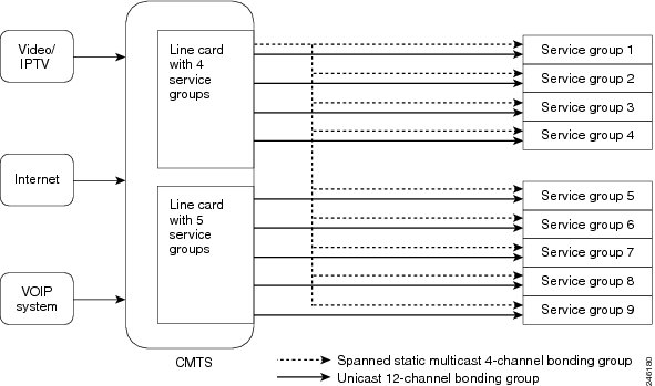
RF Spanning of Bonding Groups Carrying Static Multicast Traffic
In this RF spanning (unrestricted RF spanning) method, a downstream bonding group is configured on one of the line cards and included in one or more fiber nodes as required. Then, one or more static multicast sessions are configured for the bonding group, and any service group can use this bonding group. When this is configured, a cable modem can send a multicast join request and receive multicast streams using this bonding group. This enables service providers to broadcast a set of popular channels and make them available to customers at any time.
As shown in the figure below, each service group is made of 16 downstream channels. Of these 16 channels, 12 downstream channels are from the local card and can carry unicast traffic. The remaining four channels are from one of the line cards and spanned to all downstream service groups. These four channels can carry multicast traffic so that all service groups can use the same channels without creating any replication.
The figure below illustrates how a bonding group carries static multicast traffic.
RF Spanning of Remote Bonding Groups
In the RF spanning of remote bonding groups method, downstream channels physically located on a single line card can be used by MAC domains of a different line card for VDOC services. This method supports both unicast VDOC services and static unencrypted multicast services over RF spanned downstream bonding groups. This is similar to the RF spanning functionality supported on the shared port adapter (SPA) bonding groups together with the Cisco uBR10-MC5X20 line card. With this extended RF spanning functionality, you can directly configure remote bonding groups on the Cisco UBR-MC20X20V and Cisco uBR-MC3GX60V line cards for unicast VDOC services. Bonding groups configured on a remote line card are called remote bonding groups.
Note | We recommend using a remote bonding group and its associated channels on a single line card only to avoid bandwidth fragmentation and non-deterministic bandwidth allocation behavior. |
RF spanning of remote bonding groups is configured in the following ways:
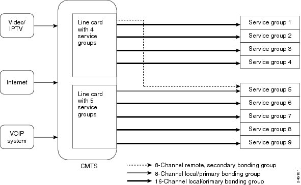
Remote Downstream to a Single Host Line Card
As shown in the figure below, each service group is made of 16 downstream channels. Because the Cisco uBR-MC3GX60V line card supports 72 downstream channels, a single line card is not sufficient to make five service groups. Therefore eight downstream channels are taken from another Cisco uBR-MC3GX60V line card to configure five service groups. Also, the service group is made of two or more bonding groups as downstream channels cannot be bonded across line cards.
The figure below illustrates how remote downstream works with a single host line card.
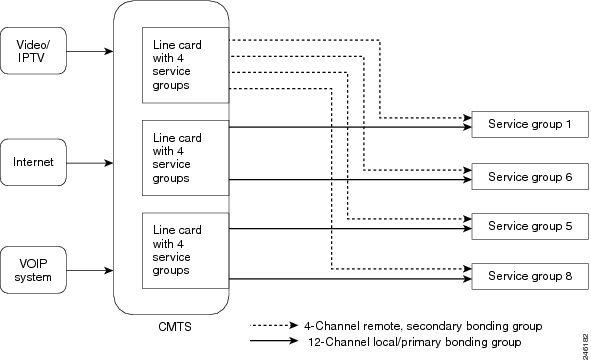
Remote Downstream to Multiple Line Cards
In this configuration, a Cisco uBR-MC3GX60V line card provides all its downstream channels to other Cisco uBR-MC3GX60V line cards installed on the Cisco uBR10012 router. As shown in the figure below, some of the downstream channels are shared with one line card and others are shared with another line card, and none are used locally.
Note | This type of configuration may not be efficient even though it is supported to provide flexibility. |
The figure below illustrates how remote downstream works with multiple line cards.
This feature also supports mixing of different types of line cards for downstream channel sharing. That is, a MAC domain configured on a Cisco UBR-MC20X20V line card can use a wideband interface configured on a Cisco uBR-MC3GX60V line card and vice versa. However, this type of configuration is generally not required and is not recommended.
RCC Template
This section describes about the RCC template selection:
Dynamic RCC Selection
The dynamic RCC selection feature facilitates multicast forwarding. The RCC selection occurs after the multicast forwarding selection algorithm identifies that the stream being requested is related to the VDOC Broadcast feature. It will select the RCC, which is superset of the primary bonding group of the cable modem, and the secondary bonding group where the stream is forwarded.
Note | The RCC template is selected only if the number of RF channels in the primary bonding group of the RCC template is same as the number of RF channels in the primary bonding group of the cable modem currently used. |
RCC Assignment Across SPAs
The VDOC Broadcast feature requires modems to be tuned to RF spanned channels carrying video streams. The RF spanned channels originate from a SPA other than the SPA hosting the primary bonding group assigned to the cable modem. RCCs are generated from RCC templates that contain Receive Channels (RC) from multiple SPAs.
Limitations while assigning RCCs are:
- For static multicast streams, only SPA downstream channels can be used in RCC templates.
- Encrypted multicast or unicast traffic is not supported on the RC from a secondary SPA.
- For encrypted or unicast downstream VDOC broadcast, traffic will not be forwarded to CPEs even when the cable modem is properly tuned to the downstream.
How to Configure VDOC Broadcast
This section describes the configuration tasks that are performed when using the VDOC broadcast feature on the Cisco CMTS platform.
- Configuring the Primary and Secondary Bonding Group (required)
- Configuring the RCC Template (required)
- Configuring the Multicast Static Group (required)
- Configuring the Primary and Secondary Bonding Group
- Configuring the RCC Template
- Configuring the Multicast Static Group
Configuring the Primary and Secondary Bonding Group
This section describes the tasks required to configure the MAC domain and the bonding group. Follow the summary steps to complete the configuration.
Configure the modular cable controller for four RF channels, two of which will be used for primary bonding group and the other two will be used for broadcasting video specific bonding groups.
Secondary bonding groups may be constructed using multiple RF channels.
- The modular controller is already configured for RF channels used for the primary and secondary bonding groups. The RF channels used for secondary bonding groups are non-primary capable and can be served by legacy Edge Quadrature Amplitude Modulation (EQAM) applications. The "udp-port" option can be used instead of Downstream External PHY Interface (DEPI) remote ID.
- The MAC domain is configured by specifying the fiber node configuration.
| Command or Action | Purpose | |||
|---|---|---|---|---|
| Step 1 | enable
Example: Router> enable |
Enables privileged EXEC mode. | ||
| Step 2 | configure
terminal
Example: Router# configure terminal |
Enters global configuration mode. | ||
| Step 3 | interface
wideband-cable
slot/subslot/port:wideband-channel
Example: Router(config)# interface wideband-cable 6/0/1:22 |
Enters cable interface configuration mode. Variables for this command may vary depending on the Cisco CMTS router and the Cisco IOS software release. For details, see the Cisco IOS CMTS Cable Command Reference .
| ||
| Step 4 | cable
bonding-group-secondary
Example: Router(config-if)# cable bonding-group-secondary |
Specifies a secondary bonding group.
| ||
| Step 5 | end
Example: Router(config-if)# end |
Exits interface configuration mode and returns to privileged EXEC mode. |
Configuring the RCC Template
This section describes the tasks required to configure the RCC template and associate it to a MAC domain.
RCC templates must be configured and then applied to the MAC domain interface. With 3-channel cable modems, the first two channels are part of the primary bonding group, and the third channel is used for video. If two RF channels are used for carrying video streams, then two RCC templates must be configured.
Modular controller and MAC domain configuration must be complete before you proceed to configuring the RCC template.
| Command or Action | Purpose | |
|---|---|---|
| Step 1 | enable
Example: Router> enable |
Enables privileged EXEC mode. |
| Step 2 | configure
terminal
Example: Router# configure terminal |
Enters global configuration mode. |
| Step 3 | interface
cable {slot/subslot/port |
slot/subslot/cable-interface-index}
Example: Router(config)# interface cable 8/0/0 |
Associates the RCC template to a MAC domain. Enters interface configuration mode. Variables for this command may vary depending on the Cisco CMTS router and the Cisco IOS software release. For details, see the Cisco IOS CMTS Cable Command Reference.
|
| Step 4 |
cable rcc-template
index
Example: Router(config)# cable rcc-template 1 |
Defines the RCC template for a Receive Channel Profile (RCP) outside the MAC domain configuration mode.
|
| Step 5 |
rcp-id
rcp-id
Example: Router(config-rcc-template)# rcp-id 0010000004 |
Configures the RCP ID.
|
| Step 6 |
receive-module
index
first-channel-center-frequency
Hz
Example: Router(config-rcc-template)# receive-module 1 first-channel-center-frequency 453000000 |
Configures the receive module.
|
| Step 7 |
receive-channel
index
center-frequency
Hz
connected-receive-module
index [primary]
Example: Router(config-rcc-template)# receive-channel 1 center-frequency 453000000 connected-receive-module 1 primary |
Configures the receive channel.
|
| Step 8 | end
Example: Router(config-rcc-template)# end |
Exits RCC template configuration mode and returns to privileged EXEC mode. |
Note | Run the show cable mac-domain cable interface rcc command to verify that RCC templates are applied to the MAC domain. |
Configuring the Multicast Static Group
Multicast static group configuration is used to statically forward (broadcast) video streams on secondary bonding groups. This configuration specifies certain video streams should be broadcast on particular bonding groups.
This section describes the tasks required to configure the multicast static group.
One or more IGMP static groups corresponding to the broadcast video channels are configured on the specified secondary bonding group. The same groups should be specified under the cable bundle interface as part of the ip igmp static-group command.
| Command or Action | Purpose | |||
|---|---|---|---|---|
| Step 1 | enable
Example: Router> enable |
Enables privileged EXEC mode.
| ||
| Step 2 | configure
terminal
Example: Router# configure terminal |
Enters global configuration mode. | ||
| Step 3 | interface
bundle
bundle-number
Example: Router# interface bundle 1 |
Indicates the bundle interface. | ||
| Step 4 | interface
wideband-cable
slot/subslot/port:wideband-channel
Example: Router(config)# interface wideband-cable 6/0/1:22 |
Enters cable interface configuration mode. Variables for this command may vary depending on the Cisco CMTS router and the Cisco IOS software release. For details, see the Cisco IOS CMTS Cable Command Reference .
| ||
| Step 5 | cable
igmp
static-group [multicast group]
source [source IP] [subinterface
number]
Example: Router(config-if)# cable igmp static-group 224.0.0.0 |
Configures the cable per physical downstream static multicast support on the Cisco CMTS.
| ||
| Step 6 | end
Example: Router(config-if)# end |
Exits interface configuration mode and returns to privileged EXEC mode. |
How to Configure Inter Line Card RF Spanning
The following tasks describe how to configure RF spanning of bonding groups carrying static multicast traffic and RF spanning of remote bonding groups to enable RF spanning on the line cards on the Cisco uBR10012 router:
- Configuring RF Spanning of Bonding Groups Carrying Static Multicast Traffic
- Configuring RF Spanning of Remote Bonding Groups
Configuring RF Spanning of Bonding Groups Carrying Static Multicast Traffic
To configure RF spanning of bonding groups carrying static multicast traffic, you need to associate downstream channels to one or more fiber nodes after configuring VDOC features on the Cisco UBR-MC20X20V and Cisco uBR-MC3GX60V line cards.
-
An RCC template must be created and associated to a MAC domain. For details, see Configuring the RCC Template
-
A multicast static group must be created. For details, see Configuring the Multicast Static Group.
RF spanning of bonding groups carrying static multicast traffic is supported only with static, unencrypted multicast.
Configuring RF Spanning of Remote Bonding Groups
To configure RF spanning of remote bonding groups, you need to configure a wideband interface on the Cisco uBR10012 router.
-
An RCC template must be created and associated to a MAC domain. For details, see Configuring the RCC Template
-
RF channels must be associated to a fiber node. For details, see Configuring RF Spanning of Bonding Groups Carrying Static Multicast Traffic.
| Command or Action | Purpose | |
|---|---|---|
| Step 1 | enable
Example: Router> enable |
Enables privileged EXEC mode.
|
| Step 2 | configure
terminal
Example: Router# configure terminal |
Enters global configuration mode. |
| Step 3 | interface
wideband-cable
slot/subslot/port:wideband-channel
Example: Router(config)# interface wideband-cable 6/0/1:22 |
Enters cable interface configuration mode. Variables for this command may vary depending on the Cisco CMTS router and the Cisco IOS software release. For details, see the Cisco IOS CMTS Cable Command Reference .
|
| Step 4 | cable
bundle
bundle-id
Example: Router(config-if)# cable bundle 1 |
Configures the wideband cable interface to belong to an interface bundle.
|
| Step 5 | cable
rf-channel
rf-channel
bandwidth-percent
bw-percent
Example: Router(config-if)# cable rf-channel 0 bandwidth-percent 25 |
Configures the bandwidth of the RF channel that would be allocated to a specified wideband channel or bonding group.
|
| Step 6 | end
Example: Router(config-if)# end |
Exits interface configuration mode and returns to privileged EXEC mode. |
Configuration Examples for VDOC Broadcast
This section describes a sample configuration example for configuring the VDOC broadcast feature.
This configuration supports four video channels (IGMP groups) over two bonding groups, with two channels over one bonding group each. Depending on the video channel selected by the set-top box, the cable modem tunes to frequencies in either RCC template 1 or 2.
- Example: Configuring the Primary and Secondary Bonding Groups
- Example: Configuring the RCC Template
- Example: Configuring the Multicast Static Group
Example: Configuring the Primary and Secondary Bonding Groups
The following example shows how to configure the primary and secondary bonding groups. This example is valid for Cisco IOS Release 12.2(33)SCD and earlier.
Note | Secondary bonding group configuration is required only for the VDOC Broadcast feature. This configuration is not required for Inter Line Card RF Spanning. |
controller modular-cable 1/0/0
 ip-address 192.0.2.0
 modular-host subslot 6/0
 rf-channel 0 cable downstream channel-id 24
 rf-channel 0 frequency 453000000 annex B modulation 256qam interleave 32
 rf-channel 0 ip-address 192.0.2.0 mac-address 0090.f001.930c depi-remote-id 20000
 rf-channel 1 cable downstream channel-id 25
 rf-channel 1 frequency 459000000 annex B modulation 256qam interleave 32
 rf-channel 1 ip-address 192.0.2.0 mac-address 0090.f001.930c depi-remote-id 21000
 rf-channel 2 cable downstream channel-id 26
 rf-channel 2 frequency 465000000 annex B modulation 256qam interleave 32
 rf-channel 2 ip-address 192.0.2.0 mac-address 0090.f001.930c depi-remote-id 21001
 rf-channel 3 cable downstream channel-id 27
 rf-channel 3 frequency 471000000 annex B modulation 256qam interleave 32
 rf-channel 3 ip-address 192.0.2.0 mac-address 0090.f001.930c depi-remote-id 21002
!
Router(config)# interface Wideband-Cable1/0/0:0
cable bundle 1
 cable bonding-group-id 1

0 bandwidth-percent 80
 cable rf-channel 1
!
Router(config)# interface Wideband-Cable1/0/0:1
 cable bundle 1
 cable bonding-group-id 2 secondary
 cable rf-channel 2
!
Router(config)# interface Wideband-Cable1/0/0:2
 cable bundle 1
 cable bonding-group-id 3 secondary
 cable rf-channel 3
!
Router(config)# interface Modular-Cable1/0/0:0
 cable bundle 1
 cable rf-bandwidth-percent 10
!
cable fiber-node 1
 downstream Modular-Cable 1/0/0 rf-channel 0-3
!
The following example shows how to configure secondary bonding groups in Cisco IOS Release 12.2(33)SCE and later.
controller modular-cable 1/0/0
 ip-address 192.0.2.0
 modular-host subslot 6/0
 rf-channel 0 cable downstream channel-id 24
 rf-channel 0 frequency 453000000 annex B modulation 256qam interleave 32
 rf-channel 0 ip-address 192.0.2.0 mac-address 0090.f001.930c depi-remote-id 20000
 rf-channel 1 cable downstream channel-id 25
 rf-channel 1 frequency 459000000 annex B modulation 256qam interleave 32
 rf-channel 1 ip-address 192.0.2.0 mac-address 0090.f001.930c depi-remote-id 21000
 rf-channel 2 cable downstream channel-id 26
 rf-channel 2 frequency 465000000 annex B modulation 256qam interleave 32
 rf-channel 2 ip-address 192.0.2.0 mac-address 0090.f001.930c depi-remote-id 21001
 rf-channel 3 cable downstream channel-id 27
 rf-channel 3 frequency 471000000 annex B modulation 256qam interleave 32
 rf-channel 3 ip-address 192.0.2.0 mac-address 0090.f001.930c depi-remote-id 21002
!
Router(config)# interface Wideband-Cable1/0/0:0
cable bundle 1
cable bonding-group-secondary
cable rf-channel 0 bandwidth-percent 80 cable rf-channel 1
!
Router(config)# interface Wideband-Cable1/0/0:1
cable bundle 1
cable bonding-group-secondary
cable rf-channel 2
!
Router(config)# interface Wideband-Cable1/0/0:2
cable bundle 1
cable bonding-group-secondary
cable rf-channel 3
!
Router(config)# interface Modular-Cable1/0/0:0
 cable bundle 1
 cable rf-bandwidth-percent 10
!
cable fiber-node 1
 downstream Modular-Cable 1/0/0 rf-channel 0-3
!
Example: Configuring the RCC Template
The following example shows how to apply RCC templates to the MAC domain host interface. The frequencies used to configure the MAC domain and bonding group are also used here.
cable rcc-template 1
  rcp-id 00 10 18 33 81
  receive-module 1 first-center-frequency 453000000
  receive-channel 1 center-frequency 453000000 connected-receive-module 1 primary
  receive-channel 2 center-frequency 459000000 connected-receive-module 1
  receive-channel 3 center-frequency 465000000 connected-receive-module 1
!
cable rcc-template 2
rcp-id 00 10 18 80 61
  receive-module 1 first-center-frequency 465000000
  receive-module 2 first-center-frequency 489000000
  receive-channel 1 center-frequency 465000000 connected-receive-module 1 primary
  receive-channel 2 center-frequency 471000000 connected-receive-module 1
  receive-channel 3 center-frequency 477000000 connected-receive-module 1
  receive-channel 4 center-frequency 483000000 connected-receive-module 1
  receive-channel 5 center-frequency 489000000 connected-receive-module 2
  receive-channel 6 center-frequency 495000000 connected-receive-module 2
  receive-channel 7 center-frequency 501000000 connected-receive-module 2
  receive-channel 8 center-frequency 507000000 connected-receive-module 2
!
interface Cable 6/0/0
 downstream Modular-Cable 1/0/0 rf-channel 0 upstream 0-3
cable rcc-template 1
cable rcc-template 2
 no cable packet-cache
 cable bundle 1
 cable downstream channel-id 119
 cable downstream annex B
 cable downstream modulation 256qam
 cable downstream interleave-depth 32
 cable downstream frequency 615000000
 cable downstream rf-shutdown
 cable upstream max-ports 4
 cable upstream 0 connector 0
 cable upstream 0 frequency 10000000
 cable upstream 0 docsis-mode tdma
 cable upstream 0 channel-width 1600000 1600000
 cable upstream 0 minislot-size 4
 cable upstream 0 range-backoff 3 6
 cable upstream 0 modulation-profile 21
 no cable upstream 0 shutdown
 cable upstream 1 connector 1
 cable upstream 1 docsis-mode tdma
 cable upstream 1 channel-width 1600000 1600000
 cable upstream 1 minislot-size 4
 cable upstream 1 range-backoff 3 6
 cable upstream 1 modulation-profile 21
 cable upstream 1 shutdown
 cable upstream 2 connector 2
 cable upstream 2 docsis-mode tdma
 cable upstream 2 channel-width 1600000 1600000
 cable upstream 2 minislot-size 4
 cable upstream 2 range-backoff 3 6
 cable upstream 2 modulation-profile 21
 cable upstream 2 shutdown
 cable upstream 3 connector 3
 cable upstream 3 docsis-mode tdma
 cable upstream 3 channel-width 1600000 1600000
 cable upstream 3 minislot-size 4
 cable upstream 3 range-backoff 3 6
 cable upstream 3 modulation-profile 21
 cable upstream 3 shutdown
!
Example: Configuring the Multicast Static Group
The following example shows how to configure multicast static groups on the bundle interface and on bonding groups in Cisco IOS Release 12.2(33)SCD and earlier:
interface Bundle 1
 ip address 192.0.2.8 255.255.255.0
 ip pim sparse-mode
 ip helper-address 2.39.16.1
 ip igmp static-group 224.0.2.1
 ip igmp static-group 224.0.2.2
 ip igmp static-group 224.0.2.3
 ip igmp static-group 224.0.2.4
 cable arp filter request-send 3 2
 cable arp filter reply-accept 3 2
!
Router(config)# interface Wideband-Cable1/0/0:1
 cable bundle 1
Router(config)#cable igmp static-group 224.0.2.3
Router(config)#cable igmp static-group 224.0.2.4
 cable bonding-group-id 2 secondary
 cable rf-channel 2
!
Router(config)#interface Wideband-Cable1/0/0:2
 cable bundle 1
Router(config)#cable igmp static-group 224.0.2.1
Router(config)#cable igmp static-group 224.0.2.2
 cable bonding-group-id 3 secondary
 cable rf-channel 3
The following example shows how to configure multicast static groups on the bundle interface and on bonding groups in Cisco IOS Release 12.2(33)SCE and later:
interface Bundle 1
 ip address 192.0.2.8 255.255.255.0
 ip pim sparse-mode
 ip helper-address 2.39.16.1
 ip igmp static-group 224.0.2.1
 ip igmp static-group 224.0.2.2
 ip igmp static-group 224.0.2.3
 ip igmp static-group 224.0.2.4
 cable arp filter request-send 3 2
 cable arp filter reply-accept 3 2
!
Router(config)# interface Wideband-Cable1/0/0:1
 cable bundle 1
Router(config)#cable igmp static-group 224.0.2.3
Router(config)#cable igmp static-group 224.0.2.4
 cable bonding-group-secondary
 cable rf-channel 2
!
Router(config)#interface Wideband-Cable1/0/0:2
 cable bundle 1
Router(config)#cable igmp static-group 224.0.2.1
Router(config)#cable igmp static-group 224.0.2.2
 cable bonding-group-secondary 3
 cable rf-channel 3
Configuration Examples for Inter Line Card RF Spanning
This section provides configuration examples for the Inter Line Card RF Spanning feature.
- Example: RF Spanning of Bonding Groups Carrying Static Multicast Traffic
- Example: RF Spanning of Remote Bonding Groups
Example: RF Spanning of Bonding Groups Carrying Static Multicast Traffic
The following example shows how to configure RF spanning of bonding groups carrying static multicast traffic on the Cisco uBR100 router:
controller Modular-Cable 1/2/0
 modular-host subslot 7/0
 rf-channel 0 cable downstream channel-id 193
 rf-channel 0 frequency 549000000 annex B modulation 256qam interleave 32
 rf-channel 0 ip-address 60.3.2.1 mac-address 0022.9084.8d7f depi-remote-id 500025
 rf-channel 1 cable downstream channel-id 194
 rf-channel 1 frequency 555000000 annex B modulation 256qam interleave 32
 rf-channel 1 ip-address 60.3.2.1 mac-address 0022.9084.8d7f depi-remote-id 500026
 rf-channel 2 cable downstream channel-id 195
 rf-channel 2 frequency 561000000 annex B modulation 256qam interleave 32
 rf-channel 2 ip-address 60.3.2.1 mac-address 0022.9084.8d7f depi-remote-id 500027
 rf-channel 3 cable downstream channel-id 196
 rf-channel 3 frequency 567000000 annex B modulation 256qam interleave 32
 rf-channel 3 ip-address 60.3.2.1 mac-address 0022.9084.8d7f depi-remote-id 500028

interface Wideband-Cable1/2/0:0
 cable bundle 11
 cable rf-channel 0 bandwidth-percent 10
 cable rf-channel 1 bandwidth-percent 10
 cable rf-channel 2 bandwidth-percent 10
 cable rf-channel 3 bandwidth-percent 10
controller Modular-Cable 5/0/0
 ip-address 60.3.2.4
 rf-channel 0 cable downstream channel-id 5
 rf-channel 0 frequency 501000000 annex B modulation 256qam interleave 32
 rf-channel 0 ip-address 60.3.2.1 mac-address 0022.9084.8d7f depi-remote-id 500017
 rf-channel 1 cable downstream channel-id 1
 rf-channel 1 frequency 507000000 annex B modulation 256qam interleave 32
 rf-channel 1 ip-address 60.3.2.1 mac-address 0022.9084.8d7f depi-remote-id 500018
 rf-channel 2 cable downstream channel-id 2
 rf-channel 2 frequency 513000000 annex B modulation 256qam interleave 32
 rf-channel 2 ip-address 60.3.2.1 mac-address 0022.9084.8d7f depi-remote-id 500019
 rf-channel 3 cable downstream channel-id 3
 rf-channel 3 frequency 519000000 annex B modulation 256qam interleave 32
 rf-channel 3 ip-address 60.3.2.1 mac-address 0022.9084.8d7f depi-remote-id 500020

interface Wideband-Cable5/0/0:0
 cable bundle 11
 cable rf-channel 0 bandwidth-percent 10
 cable rf-channel 1 bandwidth-percent 10
 cable rf-channel 2 bandwidth-percent 10
 cable rf-channel 3 bandwidth-percent 10

controller Modular-Cable 6/0/0
 ip-address 60.3.2.3
 rf-channel 0 cable downstream channel-id 4
 rf-channel 0 frequency 405000000 annex B modulation 256qam interleave 32
 rf-channel 0 ip-address 60.3.2.1 mac-address 0022.9084.8d7f depi-remote-id 500001
 rf-channel 1 cable downstream channel-id 22
 rf-channel 1 frequency 411000000 annex B modulation 256qam interleave 32
 rf-channel 1 ip-address 60.3.2.1 mac-address 0022.9084.8d7f depi-remote-id 500002
 rf-channel 2 cable downstream channel-id 23
 rf-channel 2 frequency 417000000 annex B modulation 256qam interleave 32
 rf-channel 2 ip-address 60.3.2.1 mac-address 0022.9084.8d7f depi-remote-id 500003
 rf-channel 3 cable downstream channel-id 24
 rf-channel 3 frequency 423000000 annex B modulation 256qam interleave 32
 rf-channel 3 ip-address 60.3.2.1 mac-address 0022.9084.8d7f depi-remote-id 500004
interface Wideband-Cable6/0/0:0
 cable bundle 11
 cable igmp static-group 230.1.1.1 1
 cable igmp static-group 230.5.5.5 1
 cable rf-channel 0 bandwidth-percent 10
 cable rf-channel 1 bandwidth-percent 10
 cable rf-channel 2 bandwidth-percent 10
 cable rf-channel 3 bandwidth-percent 10
cable fiber-node 50
 downstream Modular-Cable 5/0/0 rf-channel 0-3
 downstream Modular-Cable 6/0/0 rf-channel 0-3
 upstream Cable 5/0 connector 0-3
cable fiber-node 70
 downstream Modular-Cable 1/2/0 rf-channel 0-3
 downstream Modular-Cable 6/0/0 rf-channel 0-3
 upstream Cable 7/0 connector 0-3
Example: RF Spanning of Remote Bonding Groups
The following example shows how to configure RF spanning of remote bonding groups on the Cisco uBR100 router:
controller Modular-Cable 5/0/0
 ip-address 60.3.2.4
 rf-channel 0 cable downstream channel-id 5
 rf-channel 0 frequency 501000000 annex B modulation 256qam interleave 32
 rf-channel 0 ip-address 60.3.2.1 mac-address 0022.9084.8d7f depi-remote-id 500017
 rf-channel 1 cable downstream channel-id 1
 rf-channel 1 frequency 507000000 annex B modulation 256qam interleave 32
 rf-channel 1 ip-address 60.3.2.1 mac-address 0022.9084.8d7f depi-remote-id 500018
 rf-channel 2 cable downstream channel-id 2
 rf-channel 2 frequency 513000000 annex B modulation 256qam interleave 32
 rf-channel 2 ip-address 60.3.2.1 mac-address 0022.9084.8d7f depi-remote-id 500019
 rf-channel 3 cable downstream channel-id 3
 rf-channel 3 frequency 519000000 annex B modulation 256qam interleave 32
 rf-channel 3 ip-address 60.3.2.1 mac-address 0022.9084.8d7f depi-remote-id 500020

interface Wideband-Cable5/0/0:0
 cable bundle 11
 cable rf-channel 0 bandwidth-percent 10
 cable rf-channel 1 bandwidth-percent 10
 cable rf-channel 2 bandwidth-percent 10
 cable rf-channel 3 bandwidth-percent 10

controller Modular-Cable 6/0/0
 ip-address 60.3.2.3
 rf-channel 0 cable downstream channel-id 4
 rf-channel 0 frequency 405000000 annex B modulation 256qam interleave 32
 rf-channel 0 ip-address 60.3.2.1 mac-address 0022.9084.8d7f depi-remote-id 500001
 rf-channel 1 cable downstream channel-id 22
 rf-channel 1 frequency 411000000 annex B modulation 256qam interleave 32
 rf-channel 1 ip-address 60.3.2.1 mac-address 0022.9084.8d7f depi-remote-id 500002
 rf-channel 2 cable downstream channel-id 23
 rf-channel 2 frequency 417000000 annex B modulation 256qam interleave 32
 rf-channel 2 ip-address 60.3.2.1 mac-address 0022.9084.8d7f depi-remote-id 500003
 rf-channel 3 cable downstream channel-id 24
 rf-channel 3 frequency 423000000 annex B modulation 256qam interleave 32
 rf-channel 3 ip-address 60.3.2.1 mac-address 0022.9084.8d7f depi-remote-id 500004
interface Wideband-Cable6/0/0:0
 cable bundle 11
 cable igmp static-group 230.1.1.1 1
 cable igmp static-group 230.5.5.5 1
 cable rf-channel 0 bandwidth-percent 10
 cable rf-channel 1 bandwidth-percent 10
 cable rf-channel 2 bandwidth-percent 10
 cable rf-channel 3 bandwidth-percent 10
cable fiber-node 50
 downstream Modular-Cable 5/0/0 rf-channel 0-3
 downstream Modular-Cable 6/0/0 rf-channel 0-3
 upstream Cable 5/0 connector 0-3
Verifying VDOC Broadcast and Inter Line Card RF Spanning
To verify configuration of VDOC broadcast and inter line card RF spanning, use the following commands:
- show controller integrated-cable
- show controller modular-cable
- show cable multicast db
- show cable mac-domain rcc
- show cable modem service-flow
- show cable active-reman
To verify that the bonding group being shared by service groups is associated with all relevant MAC domains of the Cisco UBR-MC20X20V line card, use the show controller integrated-cable command with the association keyword as shown in the following example:
Router# show controller integrated-cable 8/0/1 association
WB Association Info for 8/0 No of WB 30
WB                      BG   Bundle  NB          NB chan  Reserved  Total
channel                 ID   num     channel     ID       CIR       CIR
Wideband-Cable8/0/0:0   1217 11      Cable7/0/0  0        0         6000000
                                     Multicast            0         6000000
Wideband-Cable8/0/0:1   1218 11      Cable7/0/0  0        0         1500000
                                     Multicast            0         1500000
Wideband-Cable8/0/0:2   1219 11      Cable7/0/0  0        0         1500000
                                     Multicast            0         1500000
Wideband-Cable8/0/1:0   1249 11      Cable7/0/0  0        0         6000000
                                     Multicast            0         6000000
To verify that the bonding group being shared by service groups is associated with all relevant MAC domains of the Cisco uBR-MC3GX60V line card, use the show controller modular-cable command with the association keyword as shown in the following example:
Router# show controller modular-cable 5/0/0 association
WB Association Info for 5/0 No of WB 96
WB                      BG   Bundle  NB          NB chan  Reserved  Total
channel                 ID   num     channel     ID       CIR       CIR
Wideband-Cable5/0/0:0   257  11      Cable5/0/0  0        0         6000000
                                     Multicast            0         6000000
Wideband-Cable5/0/0:1   258  11      Cable5/0/0  0        0         4500000
                                     Multicast            0         4500000
Wideband-Cable5/0/0:2   259  11      Cable5/0/1  0        0         6000000
                                     Multicast            0         6000000
Wideband-Cable5/0/0:3   260  11      Cable5/0/1  0        0         4500000
                                     Multicast            0         4500000
To verify the multicast bundle interface, use the show cable multicast db command with the bundle keyword as shown in the following example:
Router# show cable multicast db bundle 11
Interface : Bundle11.1
Session (S,G) : (*,230.40.40.40)
Fwd Intfc  Sub Intfc            Host Intfc   CM Mac           Hosts
Mo5/0/0:4  Bundle11.1           Ca5/0/1      ff05.0000.0024       1
Interface : Bundle11.1
Session (S,G) : (*,230.40.40.40)
Fwd Intfc  Sub Intfc            Host Intfc   CM Mac           Hosts
Mo5/0/0:0  Bundle11.1           Ca5/0/0      ff05.0000.0020       1
Interface : Bundle11.1
Session (S,G) : (*,230.40.40.40)
Fwd Intfc  Sub Intfc            Host Intfc   CM Mac           Hosts
Mo1/2/0:1  Bundle11.1           Ca7/0/0      ff01.0002.0021       1
Interface : Bundle11.1
Session (S,G) : (*,230.40.40.40)
Fwd Intfc  Sub Intfc            Host Intfc   CM Mac           Hosts
Mo1/2/0:0  Bundle11.1           Ca7/0/0      ff01.0002.0020       1
Interface : Bundle11.1
Session (S,G) : (*,230.50.50.50)
Fwd Intfc  Sub Intfc            Host Intfc   CM Mac           Hosts
Mo5/0/0:4  Bundle11.1           Ca5/0/1      ff05.0000.0024       1
Interface : Bundle11.1
Session (S,G) : (*,230.50.50.50)
Fwd Intfc  Sub Intfc            Host Intfc   CM Mac           Hosts
Mo5/0/0:0  Bundle11.1           Ca5/0/0      ff05.0000.0020       1
Interface : Bundle11.1
Session (S,G) : (*,230.50.50.50)
Fwd Intfc  Sub Intfc            Host Intfc   CM Mac           Hosts
Mo1/2/0:1  Bundle11.1           Ca7/0/0      ff01.0002.0021       1
Interface : Bundle11.1
Session (S,G) : (*,230.50.50.50)
Fwd Intfc  Sub Intfc            Host Intfc   CM Mac           Hosts
Mo1/2/0:0  Bundle11.1           Ca7/0/0      ff01.0002.0020       1
Interface : Bundle11.1
Session (S,G) : (*,230.7.7.7)
Fwd Intfc  Sub Intfc            Host Intfc   CM Mac           Hosts
Wi6/0/0:1  Bundle11.1           Ca6/0/0      ff06.0000.0001       1
Interface : Bundle11.1
Session (S,G) : (*,230.5.5.5)
Fwd Intfc  Sub Intfc            Host Intfc   CM Mac           Hosts
Wi6/0/0:0  Bundle11.1           Ca6/0/0      ff06.0000.0000       1
Interface : Bundle11.1
Session (S,G) : (*,230.2.2.2)
Fwd Intfc  Sub Intfc            Host Intfc   CM Mac           Hosts
Wi6/0/0:1  Bundle11.1           Ca6/0/0      ff06.0000.0001       1
Interface : Bundle11.1
Session (S,G) : (*,230.1.1.1)
Fwd Intfc  Sub Intfc            Host Intfc   CM Mac           Hosts
Wi6/0/0:0  Bundle11.1           Ca6/0/0      ff06.0000.0000       1
Interface : Bundle11.1
Session (S,G) : (*,230.30.30.30)
Fwd Intfc  Sub Intfc            Host Intfc   CM Mac           Hosts
Mo5/0/0:4  Bundle11.1           Ca5/0/1      ff05.0000.0024       1
Interface : Bundle11.1
Session (S,G) : (*,230.30.30.30)
Fwd Intfc  Sub Intfc            Host Intfc   CM Mac           Hosts
Mo5/0/0:0  Bundle11.1           Ca5/0/0      ff05.0000.0020       1
Interface : Bundle11.1
Session (S,G) : (*,230.30.30.30)
Fwd Intfc  Sub Intfc            Host Intfc   CM Mac           Hosts
Mo1/2/0:1  Bundle11.1           Ca7/0/0      ff01.0002.0021       1
Interface : Bundle11.1
Session (S,G) : (*,230.30.30.30)
Fwd Intfc  Sub Intfc            Host Intfc   CM Mac           Hosts
Mo1/2/0:0  Bundle11.1           Ca7/0/0      ff01.0002.0020       1
To verify that the right RCC templates are available for the remote MAC domain, use the show cable mac-domain rcc command as shown in the following example:
Router# show cable mac-domain cable 5/0/0 rcc
RCC-ID RCP RCs MD-DS-SG CMs WB/RCC-TMPL
1 00 10 00 00 04 4 1 0 RCC-TMPL (1)
2 00 10 00 00 04 4 1 8 RCC-TMPL (2)
3 00 10 00 00 04 8 1 2 RCC-TMPL (5)
4 00 10 00 00 04 8 1 2 RCC-TMPL (6)
5 00 00 00 00 00 4 0 0 WB (Wi5/0/0:0)
6 00 00 00 00 00 3 0 0 WB (Wi5/0/0:1)
7 00 00 00 00 00 2 0 0 WB (Wi5/0/0:4)
8 00 00 00 00 00 1 0 0 WB (Wi5/0/0:5)
9 00 00 00 00 00 1 0 0 WB (Wi5/0/0:6)
10 00 00 00 00 00 1 0 0 WB (Wi5/0/0:7)
11 00 00 00 00 00 1 0 0 WB (Wi5/0/0:8)
12 00 00 00 00 00 2 0 0 WB (Wi5/0/0:9)
13 00 00 00 00 00 4 0 0 WB (Wi6/0/0:1)
14 00 00 00 00 00 1 0 0 WB (Wi6/0/0:2)
15 00 00 00 00 00 1 0 0 WB (Wi6/0/0:3)
16 00 00 00 00 00 3 0 0 WB (Wi6/0/0:6)
17 00 00 00 00 00 3 0 0 WB (Wi6/0/0:7)
18 00 00 00 00 00 2 0 0 WB (Wi6/0/0:8)
To verify that the service flows are established correctly on local and remote bonding groups, use the show cable modem service-flow command as shown in the following example:
Router# show cable modem 0022.ce89.9664 service-flow
SUMMARY:
MAC Address    IP Address      Host          MAC           Prim  Num Primary
DS
                               Interface     State         Sid   CPE Downstream
RfId
0022.ce89.9664 30.13.2.74      C5/0/0/UB     w-online(pt)  1     0   Mo5/0/0:0
240
Sfid  Dir Curr  Sid   Sched  Prio MaxSusRate  MaxBrst     MinRsvRate  Throughput
          State       Type
15    US  act   1     BE     0    0           3044        0           0
16    DS  act   N/A   BE     0    1000012     6000000     0           0
33    DS  act   N/A   BE     0    1000012     6000000     0           0
UPSTREAM SERVICE FLOW DETAIL:
SFID  SID   Requests   Polls      Grants     Delayed    Dropped    Packets
                                             Grants     Grants
15    1     0          0          401        0          0          416
DOWNSTREAM SERVICE FLOW DETAIL:
SFID  RP_SFID QID    Flg Policer               Scheduler             FrwdIF
                         Xmits      Drops      Xmits      Drops
16    33559   132579     51         0          51         0          Wi5/0/0:1
33    33560   132580     0          0          0          0          Wi6/0/0:2
Flags Legend:
$: Low Latency Queue (aggregated)
~: CIR Queue
To verify the line card high availability information for all interfaces, use the show cable active-reman command as shown in the following example:
Router# show cable active-reman all
-------------------------------------------------------------
Active Reman info on LC 5/0:
[slot_index 0]:  work_slot:1/0,  active_slot:1/0,  is_protect:FALSE,  is_standby
:FALSE
[slot_index 1]:  work_slot:3/0,  active_slot:3/0,  is_protect:FALSE,  is_standby
:FALSE
[slot_index 2]:  work_slot:5/0,  active_slot:5/0,  is_protect:FALSE,  is_standby
:FALSE
[slot_index 3]:  work_slot:5/1,  active_slot:5/1,  is_protect:TRUE ,  is_standby
:TRUE
[slot_index 4]:  work_slot:6/0,  active_slot:6/0,  is_protect:FALSE,  is_standby
:FALSE
[slot_index 5]:  work_slot:6/1,  active_slot:6/1,  is_protect:FALSE,  is_standby
:FALSE
[slot_index 6]:  work_slot:7/0,  active_slot:7/0,  is_protect:FALSE,  is_standby
:FALSE
[slot_index 7]:  work_slot:7/1,  active_slot:7/1,  is_protect:FALSE,  is_standby
:FALSE
[slot_index 8]:  work_slot:8/0,  active_slot:8/0,  is_protect:FALSE,  is_standby
:FALSE
[slot_index 9]:  work_slot:8/1,  active_slot:8/1,  is_protect:FALSE,  is_standby
:FALSE
-------------------------------------------------------------
Active Reman info on LC 5/1:
[slot_index 0]:  work_slot:1/0,  active_slot:1/0,  is_protect:FALSE,  is_standby
:FALSE
[slot_index 1]:  work_slot:3/0,  active_slot:3/0,  is_protect:FALSE,  is_standby
:FALSE
[slot_index 2]:  work_slot:5/0,  active_slot:5/0,  is_protect:FALSE,  is_standby
:FALSE
[slot_index 3]:  work_slot:5/1,  active_slot:5/1,  is_protect:TRUE ,  is_standby
:TRUE
[slot_index 4]:  work_slot:6/0,  active_slot:6/0,  is_protect:FALSE,  is_standby
:FALSE
[slot_index 5]:  work_slot:6/1,  active_slot:6/1,  is_protect:FALSE,  is_standby
:FALSE
[slot_index 6]:  work_slot:7/0,  active_slot:7/0,  is_protect:FALSE,  is_standby
:FALSE
[slot_index 7]:  work_slot:7/1,  active_slot:7/1,  is_protect:FALSE,  is_standby
:FALSE
[slot_index 8]:  work_slot:8/0,  active_slot:8/0,  is_protect:FALSE,  is_standby
:FALSE
[slot_index 9]:  work_slot:8/1,  active_slot:8/1,  is_protect:FALSE,  is_standby
:FALSE
-------------------------------------------------------------
Active Reman info on LC 6/0:
[slot_index 0]:  work_slot:1/0,  active_slot:1/0,  is_protect:FALSE,  is_standby
:FALSE
[slot_index 1]:  work_slot:3/0,  active_slot:3/0,  is_protect:FALSE,  is_standby
:FALSE
[slot_index 2]:  work_slot:5/0,  active_slot:5/0,  is_protect:FALSE,  is_standby
:FALSE
[slot_index 3]:  work_slot:5/1,  active_slot:5/1,  is_protect:TRUE ,  is_standby
:TRUE
[slot_index 4]:  work_slot:6/0,  active_slot:6/0,  is_protect:FALSE,  is_standby
:FALSE
[slot_index 5]:  work_slot:6/1,  active_slot:6/1,  is_protect:FALSE,  is_standby
:FALSE
[slot_index 6]:  work_slot:7/0,  active_slot:7/0,  is_protect:FALSE,  is_standby
:FALSE
[slot_index 7]:  work_slot:7/1,  active_slot:7/1,  is_protect:FALSE,  is_standby
:FALSE
[slot_index 8]:  work_slot:8/0,  active_slot:8/0,  is_protect:FALSE,  is_standby
:FALSE
[slot_index 9]:  work_slot:8/1,  active_slot:8/1,  is_protect:FALSE,  is_standby
:FALSE
-------------------------------------------------------------
Active Reman info on LC 7/0:
[slot_index 0]:  work_slot:1/0,  active_slot:1/0,  is_protect:FALSE,  is_standby
:FALSE
[slot_index 1]:  work_slot:3/0,  active_slot:3/0,  is_protect:FALSE,  is_standby
:FALSE
[slot_index 2]:  work_slot:5/0,  active_slot:5/0,  is_protect:FALSE,  is_standby
:FALSE
[slot_index 3]:  work_slot:5/1,  active_slot:5/1,  is_protect:TRUE ,  is_standby
:TRUE
[slot_index 4]:  work_slot:6/0,  active_slot:6/0,  is_protect:FALSE,  is_standby
:FALSE
[slot_index 5]:  work_slot:6/1,  active_slot:6/1,  is_protect:FALSE,  is_standby
:FALSE
[slot_index 6]:  work_slot:7/0,  active_slot:7/0,  is_protect:FALSE,  is_standby
:FALSE
[slot_index 7]:  work_slot:7/1,  active_slot:7/1,  is_protect:FALSE,  is_standby
:FALSE
[slot_index 8]:  work_slot:8/0,  active_slot:8/0,  is_protect:FALSE,  is_standby
:FALSE
[slot_index 9]:  work_slot:8/1,  active_slot:8/1,  is_protect:FALSE,  is_standby
:FALSE
-------------------------------------------------------------
Active Reman info on LC 8/0:
[slot_index 0]:  work_slot:1/0,  active_slot:1/0,  is_protect:FALSE,  is_standby
:FALSE
[slot_index 1]:  work_slot:3/0,  active_slot:3/0,  is_protect:FALSE,  is_standby
:FALSE
[slot_index 2]:  work_slot:5/0,  active_slot:5/0,  is_protect:FALSE,  is_standby
:FALSE
[slot_index 3]:  work_slot:5/1,  active_slot:5/1,  is_protect:TRUE ,  is_standby
:TRUE
[slot_index 4]:  work_slot:6/0,  active_slot:6/0,  is_protect:FALSE,  is_standby
:FALSE
[slot_index 5]:  work_slot:6/1,  active_slot:6/1,  is_protect:FALSE,  is_standby
:FALSE
[slot_index 6]:  work_slot:7/0,  active_slot:7/0,  is_protect:FALSE,  is_standby
:FALSE
[slot_index 7]:  work_slot:7/1,  active_slot:7/1,  is_protect:FALSE,  is_standby
:FALSE
[slot_index 8]:  work_slot:8/0,  active_slot:8/0,  is_protect:FALSE,  is_standby
:FALSE
[slot_index 9]:  work_slot:8/1,  active_slot:8/1,  is_protect:FALSE,  is_standby
Additional References
The following sections provide references related to configuring the VDOC Broadcast feature.
Related Documents
|
Related Topic |
Document Title |
|---|---|
|
CMTS Command Reference |
Cisco IOS CMTS Cable Command Reference http://www.cisco.com/en/US/docs/ios/cable/command/reference/cbl_book.html http://www.cisco.com/en/US/docs/ios/cable/command/reference/cbl_book.html |
|
PacketCable and PacketCable Multimedia |
PacketCable and PacketCable Multimedia for the Cisco CMTS Routers http://www.cisco.com/en/US/docs/ios/cable/configuration/guide/cmts_pktcable_mm.html |
|
DOCSIS 3.0 multicast |
DOCSIS 3.0 Multicast Support on the CMTS Routers |
Technical Assistance
|
Description |
Link |
|---|---|
|
The Cisco Support and Documentation website provides online resources to download documentation, software, and tools. Use these resources to install and configure the software and to troubleshoot and resolve technical issues with Cisco products and technologies. Access to most tools on the Cisco Support and Documentation website requires a Cisco.com user ID and password. |
Feature Information for Configuring VDOC Broadcast
Use Cisco Feature Navigator to find information about platform support and software image support. Cisco Feature Navigator enables you to determine which software images support a specific software release, feature set, or platform. To access Cisco Feature Navigator, go to http://www.cisco.com/go/cfn. An account on Cisco.com is not required.
Note | The table below lists only the software release that introduced support for a given feature in a given software release train. Unless noted otherwise, subsequent releases of that software release train also support that feature. |
|
Feature Name |
Releases |
Feature Information |
|---|---|---|
|
IGMP-Triggered VDOC Broadcast Support |
12.2(33)SCB |
The Cisco universal broadband router supports VDOC feature enabling MSOs to broadcast video content on RF spanned downstream signals. The following sections provide information about this feature: |
|
Inter Line Card RF Spanning |
12.2(33)SCF |
The Inter Line Card RF Spanning feature supports sharing of downstream channels among the line cards installed on the Cisco uBR10012 router. The following sections provide information about this feature: The following commands were introduced or modified: |
 Feedback