Troubleshooting
This chapter provides information about the available troubleshooting tools. It contains a list of common problems and how to resolve them.
Service Monitoring
To assist in troubleshooting, Cisco Vision Director allows you to monitor the services (and servers) that are used in the solution. Pertaining to the operations of luxury suites, you can monitor Cisco Vision Director and the following:
To view the latest monitoring information:
Go to Tools > Management Dashboard > Monitor and Status > Services.
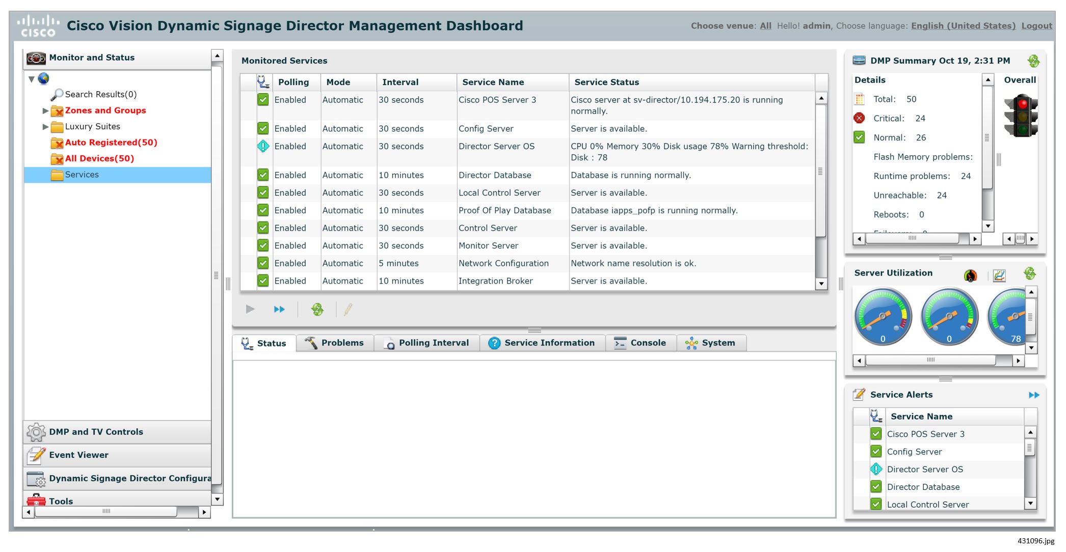
For more information about the service monitors, see Release 6.1: Cisco Vision Dynamic Signage Director Operations Guide.
Logs
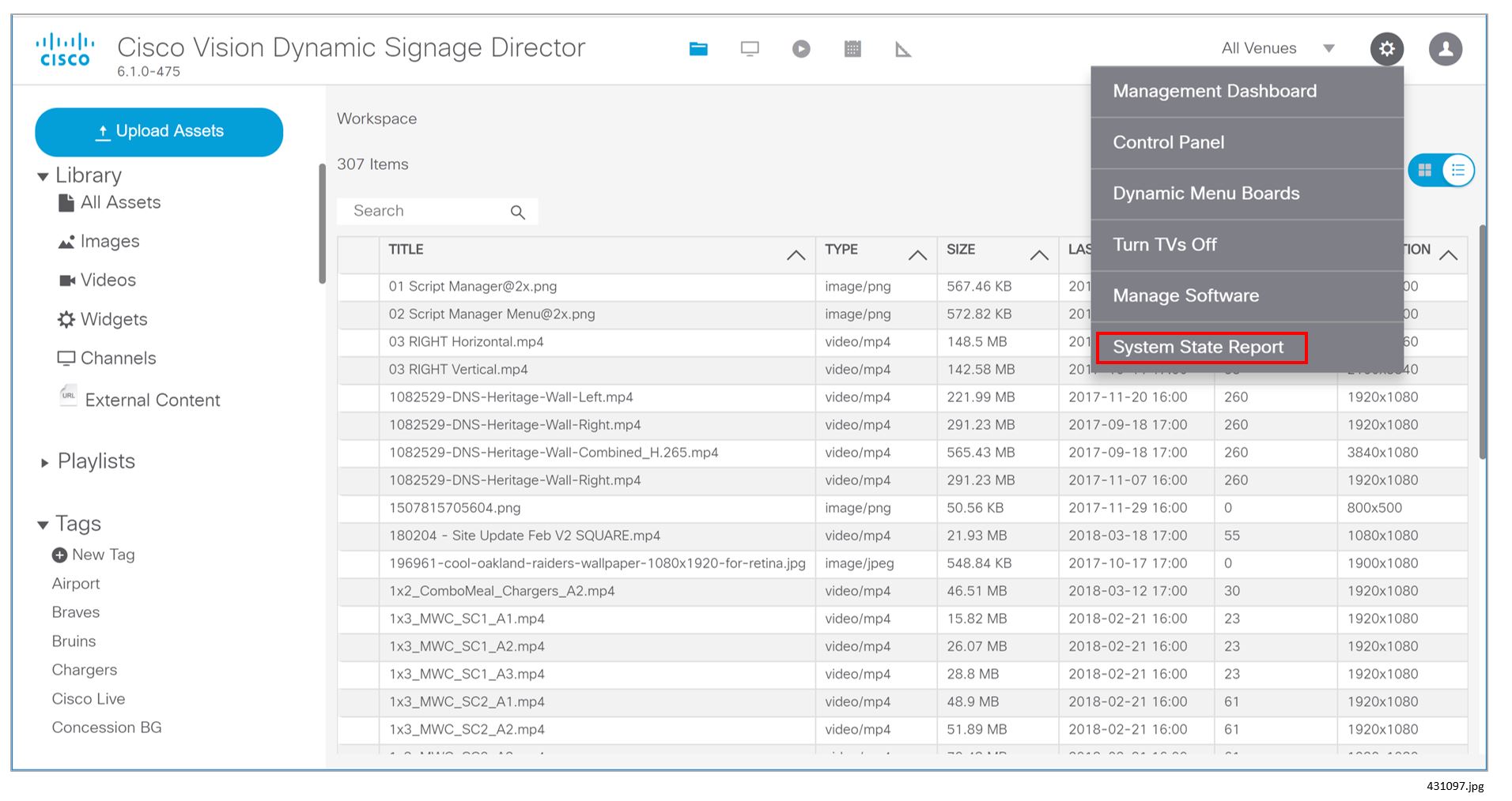
Cisco Vision Director maintains activity logs that can be accessed via the Cisco Vision Director Web UI Main Menu (Figure 1). These logs contain information that may be useful in troubleshooting. Specifically, the sv_config_problems.log is designed to log configuration errors in the system.
1.![]() Log in to Cisco Vision Director.
Log in to Cisco Vision Director.
2.![]() Go to Tools > System State Report (Figure 1).
Go to Tools > System State Report (Figure 1).
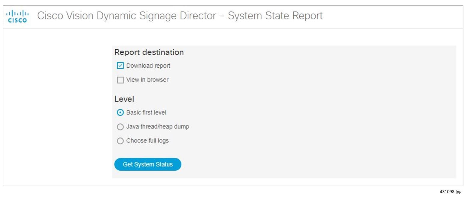
3.![]() Select the Report options and then click Get System Status.
Select the Report options and then click Get System Status.
Log information for Local Control is dispersed across a number of different log files as follows:
/var/log/httpd/access_log: Contains the incoming http request from the IP phone
/opt/sv/servers/control/logs/sv_external.log: A summary of the communications from Cisco Vision Director to phone.
/opt/sv/servers/control/logs/sv_phone_xml.log: Shows the raw XML that is returned by Cisco Vision Director to the phone.
/opt/sv/servers/control/logs/sv_debug.log: Shows the internal processing as a phone request is handled by Cisco Vision Director.
To access the log information:
1.![]() Use the Service button on the phone to bring up the main menu of the Cisco Vision application. Check the Apache logs to confirm that this results in an http GET message being received by Cisco Vision Director:
Use the Service button on the phone to bring up the main menu of the Cisco Vision application. Check the Apache logs to confirm that this results in an http GET message being received by Cisco Vision Director:
[root@user-svd1 httpd]# grep 10.10.99.3 access_log 10.10.99.3 - - [31/Oct/2011:17:27:19 -0600] GET
/Vision Director/images/phone/phone/phoneImages/saved/SEP0026CBC01B64_homePage.png
HTTP/1.1 200 15606 - Allegro-Software-WebClient/4.34
2.![]() Check sv_external.log to see the requests that have been received from the phone and processed. The log snippet below reflects the following sequence of buttons being pressed on the phone:
Check sv_external.log to see the requests that have been received from the phone and processed. The log snippet below reflects the following sequence of buttons being pressed on the phone:
a.![]() Service button pressed. Brings up CV main menu - ListServices
Service button pressed. Brings up CV main menu - ListServices
b.![]() TV/Volume key pressed. Brings up display selection screen - DisplaySelect
TV/Volume key pressed. Brings up display selection screen - DisplaySelect
c.![]() TV/DMP with IP addr 10.10.99.29 selected. Displays channel guide - Device
TV/DMP with IP addr 10.10.99.29 selected. Displays channel guide - Device
d.![]() Channel 3 selected - Channel
Channel 3 selected - Channel
e.![]() Volume down key pressed - VolumeDown
Volume down key pressed - VolumeDown
f.![]() Screen returns to main SV menu after timeout - ListServices
Screen returns to main SV menu after timeout - ListServices
3.![]() In the previous step, notice how each log message in sv_external.log contains an 8-digit log message ID immediately following the phone IP address. This ID can be used to find related messages in the other log files in the same directory. In the following example log messages with ID
In the previous step, notice how each log message in sv_external.log contains an 8-digit log message ID immediately following the phone IP address. This ID can be used to find related messages in the other log files in the same directory. In the following example log messages with ID
can be found in five different log files. Notice how the timestamps are within one second of each other, emphasizing that they are all part of the same transaction:
4.![]() Check the sv_phone_xml.log to perform a sanity check of the XML returned to the phone. The XML in the example below corresponds to the be0d5d69 entry in sv_external.log in Step 2 above. That displays the channel guide. The XML below describes two channels (KGO-HD and LIVEWELL HD) and for each defines the X,Y touch area and the channel change URL that is fired when touched.
Check the sv_phone_xml.log to perform a sanity check of the XML returned to the phone. The XML in the example below corresponds to the be0d5d69 entry in sv_external.log in Step 2 above. That displays the channel guide. The XML below describes two channels (KGO-HD and LIVEWELL HD) and for each defines the X,Y touch area and the channel change URL that is fired when touched.
The format of the XML is documented at: http://www.cisco.com/en/US/docs/voice_ip_comm/cuipph/all_models/xsi/7_1_3/xmlobjects.html
5.![]() The sv_msg_trace.log file contains log messages for all communication between Cisco Vision Director and the DMPs being controlled. The example below corresponds to the channel change in step 2 (log message ID 80ecc133). The channel change button press on the phone results in three commands being sent to the DMP with IP address 10.10.99.29 as follows:
The sv_msg_trace.log file contains log messages for all communication between Cisco Vision Director and the DMPs being controlled. The example below corresponds to the channel change in step 2 (log message ID 80ecc133). The channel change button press on the phone results in three commands being sent to the DMP with IP address 10.10.99.29 as follows:
a.![]() setKeyCode: Sends IR key code 158 to the DMP
setKeyCode: Sends IR key code 158 to the DMP
b.![]() setVideoChannel: Sets the video channel to udp://239.200.0.103:4000
setVideoChannel: Sets the video channel to udp://239.200.0.103:4000
c.![]() setDisplayBanner: Activates the display banner for 5000 msec.
setDisplayBanner: Activates the display banner for 5000 msec.
For more information on Cisco Vision Director Logs, see Cisco Unified Real-Time Monitoring Tool Administration Guide.
Common Problems
Table 1shows some common problems and their resolutions.
The Welcome screen in a luxury suite shows up on the wrong display. |
The video display is configured incorrectly in Cisco Vision Director. |
Determine the IP address of the DMP either by looking at the DMP or by using a Cisco IR Remote. Assure this video display is in the correct group. |
There was a state change and the script for this event did not specify No change for the channel. A configuration error in Cisco Vision Director defines a controller outside of this suite as the suite controller. |
If this is not the desired action, go to the script for this or subsequent events and set the action to “No Change” for the channel on this display. Correct the configuration so that only the controller in this suite has control over the DMPs in this suite. |
|
The graphic is not loaded correctly in CUCM. |
Ensure that the graphic is in the correct format and is loaded into CUCM in the correct location. See Loading the Cisco Vision Director IP Phone Desktop Graphic. Check /opt/apache-tomcat- 6.0.18/logs/sv_dev_debug.log for errors. Look for a message similar to the following: 2010-02-23 22:57:30,659 [pool-6-thread-20] ERROR |
|
The user ID and password of the IP Phone is not correctly configured in Cisco Vision Director. |
Ensure that the phoneDefaultPassword and phoneDefaultUsername are correctly configured in Cisco Vision Director. See Setting IP Phone Passwords. |
|
The user ID and password of the IP Phone is not correctly configured in CUCM. |
Ensure that the user credentials are correctly set in CUCM. See Verifying IP Phone Credentials. |
Verifying IP Phone Credentials
If the credentials for the IP Phone are not set correctly in CUCM and in Cisco Vision Director, you will not be able to change the phone background graphic or speed dials.
Within Cisco Vision Director, the IP Phone credentials can be specified in two places:
■![]() Go to T ools > Management Dashboard > Tools drawer > Advanced tab > Registry. This is used to specify the “global credentials” for IP Phones. See Setting IP Phone Passwords for more information.
Go to T ools > Management Dashboard > Tools drawer > Advanced tab > Registry. This is used to specify the “global credentials” for IP Phones. See Setting IP Phone Passwords for more information.
■![]() Go to Tools > Control Panel > Setup > Devices > IP Phones. The Admin ID and Admin Password fields on this page should only be specified if the phone has credentials that are unique from other phones. See Defining Cisco IP Phones for more information.
Go to Tools > Control Panel > Setup > Devices > IP Phones. The Admin ID and Admin Password fields on this page should only be specified if the phone has credentials that are unique from other phones. See Defining Cisco IP Phones for more information.
Refer to the section Configuring CUCM Integration for credentials configurations.
Verifying Credentials Configured in the Cisco Vision Director Registry
To verify the credentials when they are configured using the Cisco Vision Director registry:
1.![]() Enter the following into a browser:
Enter the following into a browser:
where <CUCM_IP_addr> is replaced by the IP address of Call Manager.
2.![]() At the prompt to enter a username and password, enter the credentials that were configured in the Cisco Vision Director registry for CCMPass and CCMUser.
At the prompt to enter a username and password, enter the credentials that were configured in the Cisco Vision Director registry for CCMPass and CCMUser.
3.![]() If the credentials are entered correctly, the following will display in the browser window:
If the credentials are entered correctly, the following will display in the browser window:
Cisco CallManager: AXL Web Service
The AXL Web Service is working and accepting requests. Use HTTP POST to send a request.
Verifying Credentials Configured Using the IP Phone Setup in Cisco Vision Director
When using the IP Phone configuration page in the Cisco Vision Director, go to Tools > Control Panel > Setup > Suites, verify the credentials.
To verify the credentials when using the IP Phone admin ID and password:
1.![]() Enter the following URL in a browser:
Enter the following URL in a browser:
http://<CUCM_IP_addr>/ccmcip/authenticate.jsp?UserID=<user_ID>&Password=<password>&de vicename=SEP<mac_address>
where <CUCM_IP_addr> is replaced by the IP address of Call Manager, the <user_ID> and <password> in the URL correspond to the admin credentials from Cisco Vision Director, and the <mac_address> is the MAC address of the phone.
2.![]() If the credentials are entered correctly, the word AUTHORIZED displays in the window.
If the credentials are entered correctly, the word AUTHORIZED displays in the window.
 Feedback