- Prerequisites
- Implementation Guidelines
- Implementation Summary
- CUCM Configuration
- Configuring CUCM to Provide Cisco Vision Director Services
- Configuring Luxury Suite Speed Dials
- Configuring the Background CUCM End User (IP Phone User)
- Cisco Vision Director Configuration
- Configuring CUCM Integration
- Setting IP Phone Passwords
- Defining Local TV Control Devices in Cisco Vision Director
- Defining Luxury Suites in Cisco Vision Director
- Providing a Welcome Message on a Luxury Suite TV
- Defining Channel Lineup (Guide)
- Controlling the Behavior of the Channel Guide
- Changing the IP Phone Background
- Adjusting IP Phone Timeout Values
- Labeling TV External Inputs
Implementation
This chapter provides information about how to implement local TV control in a Cisco Vision Director venue.
Prerequisites
Complete the following, which are not discussed in this guide, before implementing local TV control.
Release 6.1: Cisco Vision Deployment Guide for Series 2 and Series 3 Media Players: Dynamic Signage Director |
|
Release 6.1: Cisco Vision Deployment Guide for Series 2 and Series 3 Media Players: Dynamic Signage Director |
|
Release 6.1: Cisco Vision Deployment Guide for Series 2 and Series 3 Media Players: Dynamic Signage Director |
|
Release 6.1: Cisco Vision Deployment Guide for Series 2 and Series 3 Media Players: Dynamic Signage Director |
|
IP Multicast streams mapped to local channels in Cisco Vision Director |
Release 6.1: Cisco Vision Content Planning and Specifications Guide: Dynamic Signage Director |
Release 6.1: Cisco Vision Content Planning and Specifications Guide: Dynamic Signage Director |
|
Templates, event scripts, and additional content defined in Cisco Vision Director |
Release 6.1: Cisco Vision Content Planning and Specifications Guide: Dynamic Signage Director |
Cisco Unified Communications Manager installed/configured (if IP Phone used) |
Implementation Guidelines
Keep the following in mind as you design and implement local TV control:
■![]() Any designated area requiring local TV control (restaurant, club, bar, back office, locker room, press box) must be configured as a “Luxury Suite” within Cisco Vision Director.
Any designated area requiring local TV control (restaurant, club, bar, back office, locker room, press box) must be configured as a “Luxury Suite” within Cisco Vision Director.
■![]() When an IP phone is used as the local control device for a designated area, it is configured using the “IP Phone” tab of the “Luxury Suite” page.
When an IP phone is used as the local control device for a designated area, it is configured using the “IP Phone” tab of the “Luxury Suite” page.
■![]() When a third-party device is used for local control, it is configured using the “Local Control” tab of the “Luxury Suite” page.
When a third-party device is used for local control, it is configured using the “Local Control” tab of the “Luxury Suite” page.
■![]() Cisco Vision Director recognizes an IP phone by its IP address. Therefore, the phone’s IP address must remain the same. This means that the IP address needs to be statically configured, or the DHCP server must be configured to always hand out the same IP address to a specific phone MAC address.
Cisco Vision Director recognizes an IP phone by its IP address. Therefore, the phone’s IP address must remain the same. This means that the IP address needs to be statically configured, or the DHCP server must be configured to always hand out the same IP address to a specific phone MAC address.
■![]() The Cisco Vision Director service includes pre-defined softkeys. An alternative set of softkeys is available. See the “Alternative Softkey Mapping” section for more information.
The Cisco Vision Director service includes pre-defined softkeys. An alternative set of softkeys is available. See the “Alternative Softkey Mapping” section for more information.
Implementation Summary
This section provides a high-level overview of what must be configured in support of local TV control.
Graphic Specifications
The graphics (or images) used in the deployment of a luxury suite are stored in different locations and have different specifications.
Information about how to load these files on the various devices is provided in subsequent sections.
Note on Changing the Phone Background in Cisco Vision Director
Cisco Vision Director includes the ability to deploy IP phone backgrounds. However, this method of deployment is only recommended for the initial background graphic deployment. Note the following guidelines before using:
■![]() It requires that all phones are associated to a single user in CUCM.
It requires that all phones are associated to a single user in CUCM.
■![]() It requires that the Settings button on the IP Phones be enabled whenever it is invoked (security risk); this requires a phone reset.
It requires that the Settings button on the IP Phones be enabled whenever it is invoked (security risk); this requires a phone reset.
■![]() It requires that the phone be enabled to “allow end user changing of the backgrounds.”
It requires that the phone be enabled to “allow end user changing of the backgrounds.”
■![]() It requires that the IP Phone be in a specific state at the time of launch or it may not work (must be on call services display; if left on Directory or Settings it may not work).
It requires that the IP Phone be in a specific state at the time of launch or it may not work (must be on call services display; if left on Directory or Settings it may not work).
■![]() It uses simulated key presses to execute the background change, which is invasive as each press is visible on the phone as it is being executed.
It uses simulated key presses to execute the background change, which is invasive as each press is visible on the phone as it is being executed.
■![]() It is not capable of pushing different images to different groups of phones (for example, stadium background on office phones versus event background on suite phones); it will either push to all phones at once or one at a time.
It is not capable of pushing different images to different groups of phones (for example, stadium background on office phones versus event background on suite phones); it will either push to all phones at once or one at a time.
■![]() It is suitable only for a one-time initial bulk deployment, but is not scalable beyond that due to the settings changes that would be required on the phones for each push (enable settings in CUCM, push graphic, disable settings; this results in multiple resets to the phone).
It is suitable only for a one-time initial bulk deployment, but is not scalable beyond that due to the settings changes that would be required on the phones for each push (enable settings in CUCM, push graphic, disable settings; this results in multiple resets to the phone).
■![]() No error reporting exists; therefore, there is no way of knowing that the background was applied to a specific phone.
No error reporting exists; therefore, there is no way of knowing that the background was applied to a specific phone.
As an alternative, you can use a third-party application called VoIP Integration Background Deployer for bulk background deployment.
Enabling IP Phones for Local TV Control
After the Cisco IP Phone and CUCM have been installed and are operational, do the following to enable the Cisco IP Phone to act as local control for a designated area (such as a luxury suite):
| ■ ■ – – |
|
| ■ ■ ■ ■ ■ |
Release 6.1: Cisco Vision Dynamic Signage Director Administration Guide |
Enabling Third-Party Touch Panels for Local TV Control
Work with the Crestron or AMX integration partner to ensure that the touch-panel is operational (connected to the network). If you have developed an application with the User Control API, other considerations, such as wireless connectivity, may need to be addressed.
To enable the third-party touch panel to act as local control for a designated area (such as a restaurant or club), do the following:
| ■ ■ ■ |
Release 6.1: Cisco Vision Dynamic Signage Director Administration Guide |
CUCM Configuration
■![]() A phone service must be added to enable the phone to access the Cisco Vision Director services.
A phone service must be added to enable the phone to access the Cisco Vision Director services.
■![]() Determine how the phone will display the Cisco Vision Director services (the idle URL configuration is discussed below).
Determine how the phone will display the Cisco Vision Director services (the idle URL configuration is discussed below).
■![]() (Optional) Speed dials for services such as housekeeping or security, which require an Application User be created if they are to be accessible via the Cisco Vision Director Services Home page.
(Optional) Speed dials for services such as housekeeping or security, which require an Application User be created if they are to be accessible via the Cisco Vision Director Services Home page.
■![]() The Cisco Vision Director phone background graphic must be stored on CUCM.
The Cisco Vision Director phone background graphic must be stored on CUCM.
Configuring CUCM to Provide Cisco Vision Director Services
If the Cisco IP Phone is used for local TV control, the phone must have access to the appropriate services within CUCM.
To configure CUCM to provide Cisco Vision Director services to the Cisco IP Phone:
■![]() Configure the Cisco Vision Director Services
Configure the Cisco Vision Director Services
■![]() Subscribe the phones to the appropriate services
Subscribe the phones to the appropriate services
To add Cisco Vision Director Services:
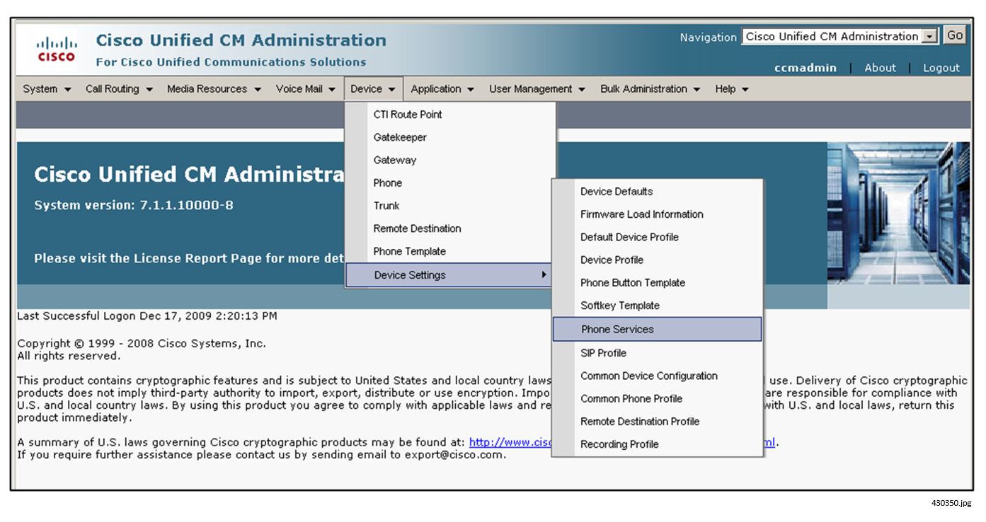
1.![]() On the Cisco Unified CM Administration page, select Device > Device Settings > Phone Services.
On the Cisco Unified CM Administration page, select Device > Device Settings > Phone Services.
2.![]() In the Find and List IP Phone Services window, click the Add New icon. The IP Phone Services Configuration window displays.
In the Find and List IP Phone Services window, click the Add New icon. The IP Phone Services Configuration window displays.
Service Name: Cisco Vision Director Services
Service Description: Cisco Vision Director Services Service URL:
–![]() http://<SV Director IP addr>:8080/Vision Director/jsp/Sports?vc=no&device=#DEVICENAME#
http://<SV Director IP addr>:8080/Vision Director/jsp/Sports?vc=no&device=#DEVICENAME#
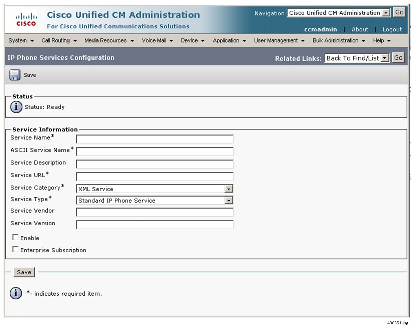
4.![]() Select the Enable check box. Do not select the Enterprise Subscription check box.
Select the Enable check box. Do not select the Enterprise Subscription check box.
5.![]() Click Save. The page redisplays.
Click Save. The page redisplays.
7.![]() Click Save on the IP Phone Services Configuration page.
Click Save on the IP Phone Services Configuration page.
To subscribe Phones to Cisco Vision Director Services:
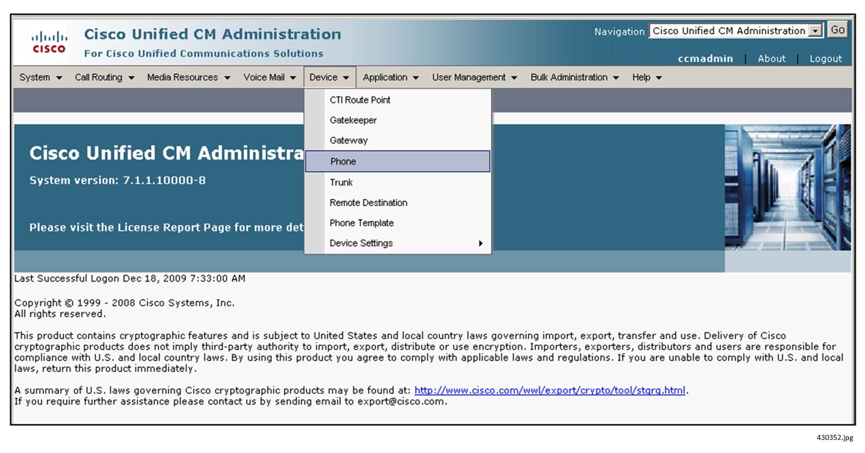
1.![]() On the Cisco Unified CM Administration page, select Device > Phone.
On the Cisco Unified CM Administration page, select Device > Phone.
2.![]() To display a list of devices, click Find. The window redisplays.
To display a list of devices, click Find. The window redisplays.
3.![]() Click the Device Name of the phone. The Phone Configuration window displays.
Click the Device Name of the phone. The Phone Configuration window displays.
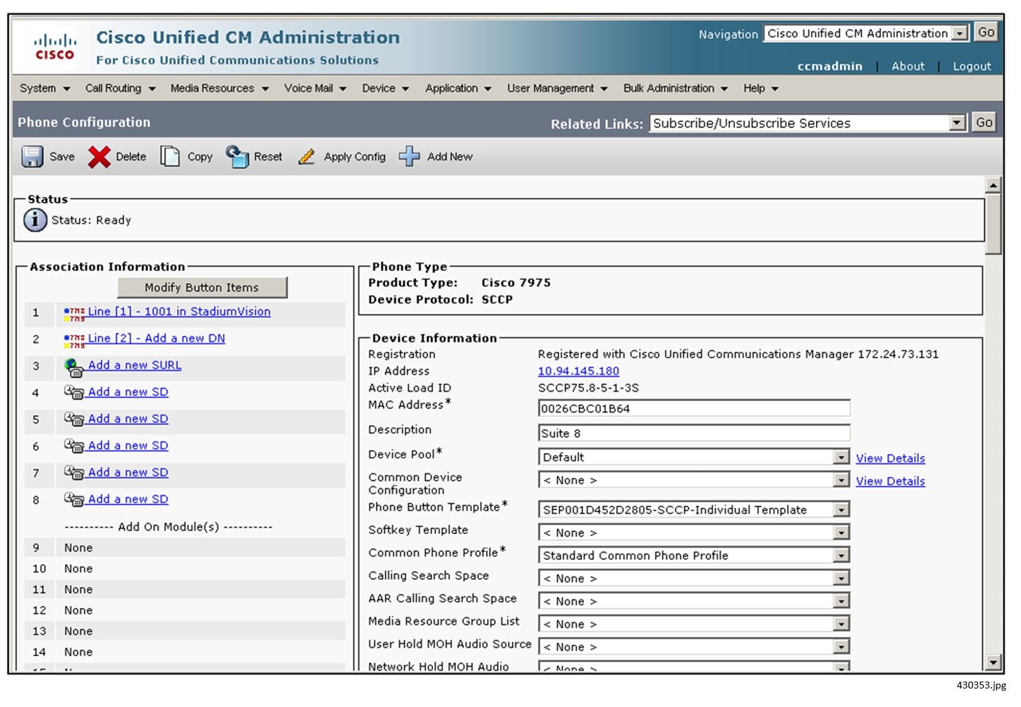
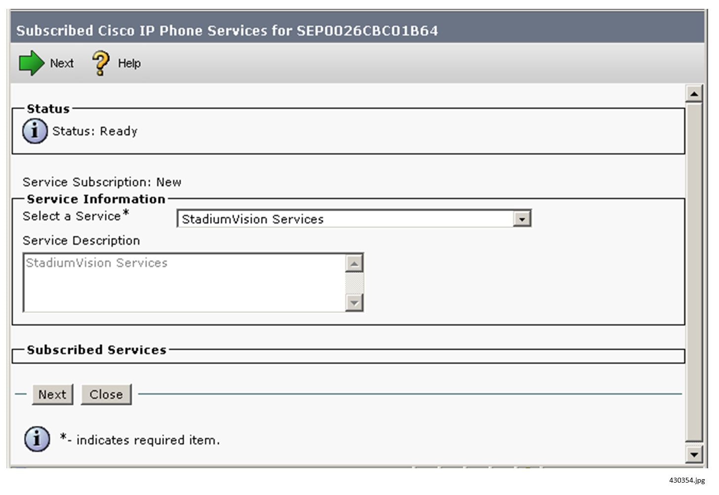
4.![]() In the Related Links pull-down (upper right), click Subscribe/Unsubscribe Services and then click Go. The Subscribed Cisco IP Phone Services window displays.
In the Related Links pull-down (upper right), click Subscribe/Unsubscribe Services and then click Go. The Subscribed Cisco IP Phone Services window displays.
5.![]() In the Select a Service field, choose Cisco Vision Director Services and then click Close.
In the Select a Service field, choose Cisco Vision Director Services and then click Close.
6.![]() To cause the Cisco Vision Director Services page to display by default on the phone, scroll down to the section titled External Data Locations Information.
To cause the Cisco Vision Director Services page to display by default on the phone, scroll down to the section titled External Data Locations Information.
If the phone will be located in a luxury suite, we recommend that the Cisco Vision Director Services page be the default display on the phone. In this case, modify the information on this page as described below.
If the phone will be located in a back office or other administrative situation, we recommend that the standard CUCM call services be the default. In this case, skip this step.
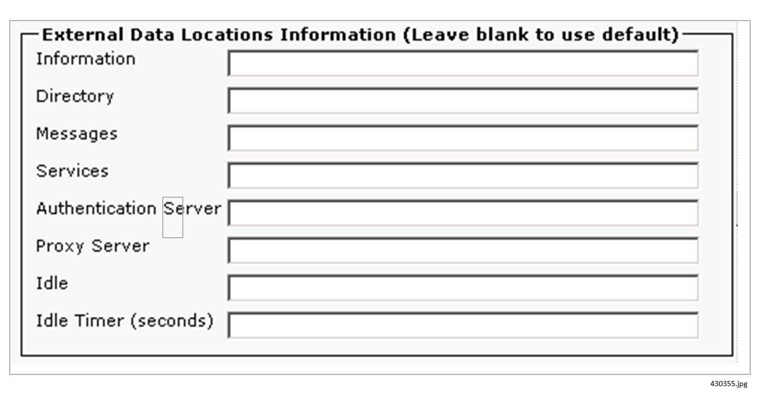
In the Idle field, enter: http://<SV Director IP addr>:8080/Vision Director/jsp/Sports?vc=no
Configuring Luxury Suite Speed Dials
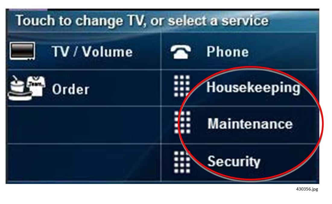
Within luxury suites, a venue can configure speed dials for the convenience of the guests. Up to three (3) speed dials can be displayed on the Cisco Vision Director Home page. Recommended speed dials include concierge, housekeeping, and security.
Cisco Vision Director uses the CUCM AXL API to query the CUCM for the phone's speed dial configurations. Cisco Vision Director then takes the speed dial text label and pointer and displays it on the Cisco Vision Director Home page (figure shown below).
Configuring speed dials for the Cisco Vision Director solution is a four-step process:
1.![]() Configure the speed dials on the phone within CUCM:
Configure the speed dials on the phone within CUCM:
–![]() They must be assigned to a button on the phone
They must be assigned to a button on the phone
–![]() BLF Speed dial buttons will not work, only standard speed dial buttons
BLF Speed dial buttons will not work, only standard speed dial buttons
2.![]() Create the Application user in CUCM for Cisco Vision Director AXL access.
Create the Application user in CUCM for Cisco Vision Director AXL access.
3.![]() Identify the CUCM server to Cisco Vision Director and provide the CUCM user ID and password.
Identify the CUCM server to Cisco Vision Director and provide the CUCM user ID and password.
4.![]() Confirm that the CUCM db schema version configured in the Cisco Vision Director registry matches that of the CUCM (refer to Cisco Vision Director Configuration section).
Confirm that the CUCM db schema version configured in the Cisco Vision Director registry matches that of the CUCM (refer to Cisco Vision Director Configuration section).
The first three speed dials that you configure in CUCM are displayed on the Cisco Vision Director service plane, as shown below.
To configure the speed dials within CUCM:
2.![]() Locate and select the appropriate phone.
Locate and select the appropriate phone.
3.![]() In the Association Information section (on the left), click Add a new SD beside the desired button.
In the Association Information section (on the left), click Add a new SD beside the desired button.
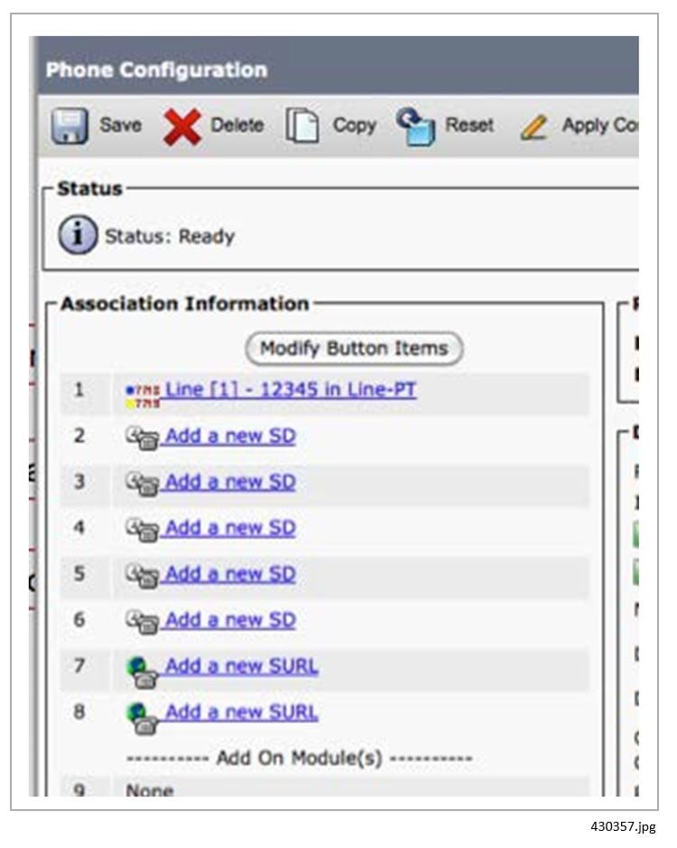
4.![]() Enter the phone number and a label (such as Housekeeping or Security).
Enter the phone number and a label (such as Housekeeping or Security).
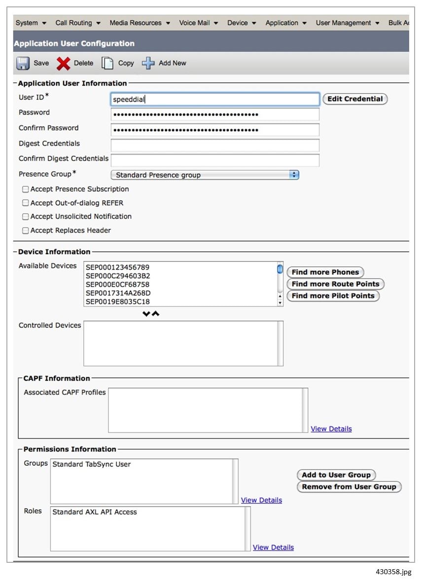
To configure the application user within CUCM:
1.![]() From User Management > Application User, click Add new.
From User Management > Application User, click Add new.
2.![]() Configure a user name and password.
Configure a user name and password.
4.![]() Search for and select the Standard TabSynch User.
Search for and select the Standard TabSynch User.
Note: Cisco Vision Director caches the speed dial information to reduce the number of requests to CUCM. If a speed dial LABEL is modified on the phone via CUCM, the Cisco Vision Director Services must be restarted so that the correct speed dial labels are displayed.
In addition, if the CUCM is integrated with Active Directory, this will not affect the application user since all application users are local accounts on CUCM.
Loading the Cisco Vision Director IP Phone Desktop Graphic
To enhance the Cisco Vision Director user experience, the phone desktop graphic (or background) should be changed to the graphic that is provided in Cisco Vision Director.

The recommended desktop graphics and a List.xml file are included in a zip file located on the Cisco Vision Director server at:
■![]() http://<SV_director_ip_addr>:8080//download/cucmitems-<version-build>.zip
http://<SV_director_ip_addr>:8080//download/cucmitems-<version-build>.zip
First, the graphic must be made available to the phone, which requires that the graphic be stored on the CUCM server.
1.![]() Download the cucmitems-<version-build>.zip file to your PC.
Download the cucmitems-<version-build>.zip file to your PC.
2.![]() Unzip the file and review the contents, as necessary. The file contains two directories. Each directory contains a number of files, including the background image, a thumbnail version (80x53) of the image, and a List.xml file.
Unzip the file and review the contents, as necessary. The file contains two directories. Each directory contains a number of files, including the background image, a thumbnail version (80x53) of the image, and a List.xml file.
If you opt to create a separate PNG file, be sure to create a thumbnail version (80x53) and update the List.xml file. The format of the provided List.xml file is:
For more information, see the CUCM IP Phone Administration documentation. You can include up to eight (8) background images in the List.xml file. Make note of the order in which the images are listed because you will need to know this when changing the image using Cisco Vision Director. See Changing the IP Phone Background.
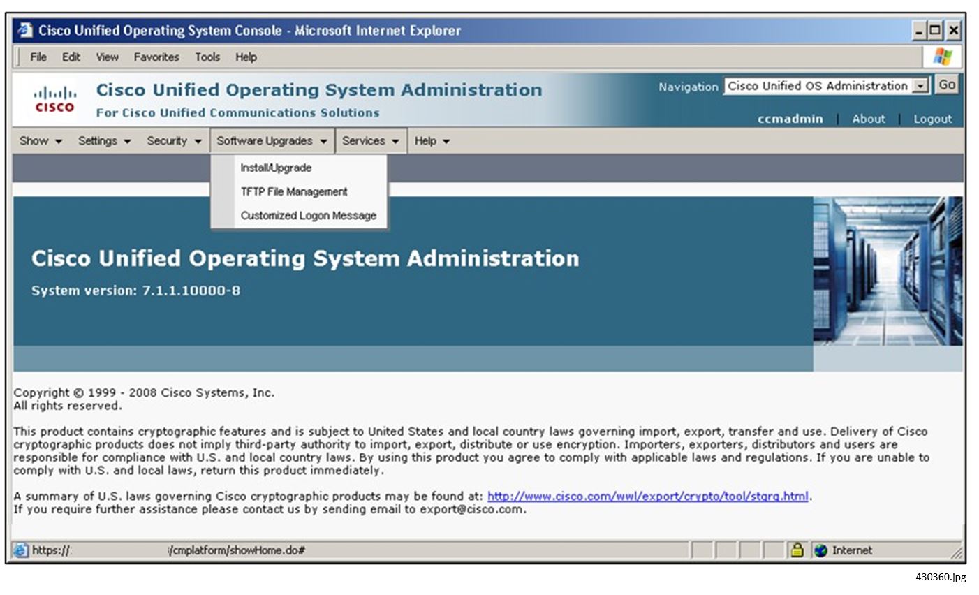
3.![]() On the Cisco Unified Operating System Administration window, select Software Updates > TFTP File Management.
On the Cisco Unified Operating System Administration window, select Software Updates > TFTP File Management.
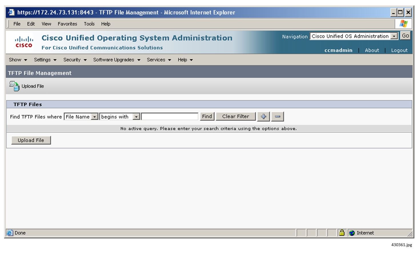
4.![]() On the TFTP File Management page, click the Upload File icon.
On the TFTP File Management page, click the Upload File icon.
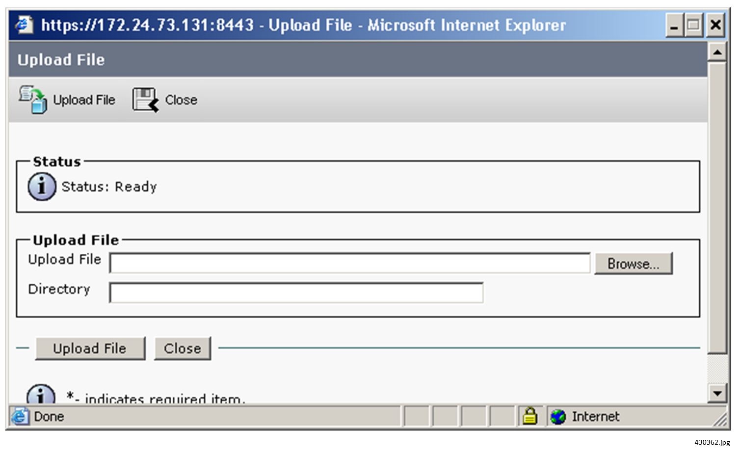
5.![]() Browse to select the desired files and upload them to a directory named /Desktops/320x216x16.
Browse to select the desired files and upload them to a directory named /Desktops/320x216x16.
Note: The file name and subdirectory parameters are case sensitive. Be sure to use the forward slash / when you specify the subdirectory path.
6.![]() Use the Cisco Vision Director to specify which background the phone should use. (See Changing the IP Phone Background.)
Use the Cisco Vision Director to specify which background the phone should use. (See Changing the IP Phone Background.)
Alternatively, go to Settings > User Preferences > Background Images. (It may take a few minutes for all of the images to load.) Click the number that corresponds to the desired graphic. Click Save and then click Exit.
7.![]() To cache the new List.xml file, restart the TFTP server:
To cache the new List.xml file, restart the TFTP server:
a.![]() On the Cisco Unified Serviceability page, select Tools > Control Center - Feature Services.
On the Cisco Unified Serviceability page, select Tools > Control Center - Feature Services.
b.![]() Click the CM Server running the TFTP service, and then click Go.
Click the CM Server running the TFTP service, and then click Go.
c.![]() Click the radio button next to Cisco TFTP, scroll down, and then click Restart.
Click the radio button next to Cisco TFTP, scroll down, and then click Restart.
Configuring the Background CUCM End User (IP Phone User)
To configure the IP Phone User for Phone Background Access via Cisco Vision Director:
1.![]() For Suite or Public-facing phones, a single end user can be created for phone backgrounds.
For Suite or Public-facing phones, a single end user can be created for phone backgrounds.
2.![]() Administrative and office phones are typically associated with the user who owns the phone. These passwords typically will not be shared; again, a single user can be created for this (can use same end user for all phones).
Administrative and office phones are typically associated with the user who owns the phone. These passwords typically will not be shared; again, a single user can be created for this (can use same end user for all phones).
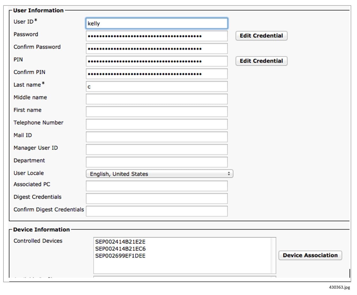
3.![]() End Users are created via CUCM in User Management > End User.
End Users are created via CUCM in User Management > End User.
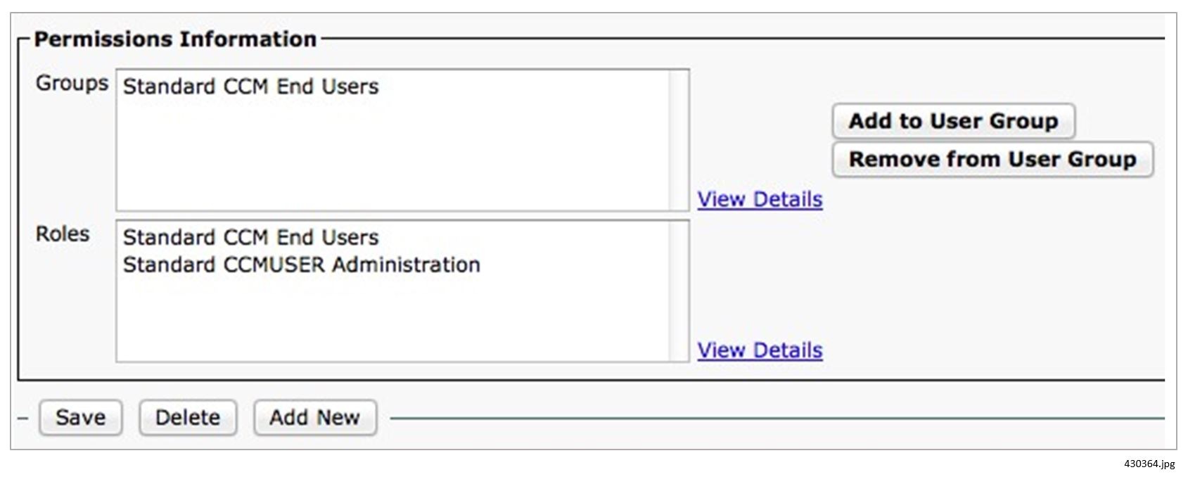
4.![]() The end user must be assigned to the Standard CCM End Users group.
The end user must be assigned to the Standard CCM End Users group.
5.![]() The device(s) must be associated to the End User. Click the Device Association button and search for/select all relevant devices.
The device(s) must be associated to the End User. Click the Device Association button and search for/select all relevant devices.
6.![]() IF CUCM is integrated with Active Directory, you will not be able to create the end user in CUCM:
IF CUCM is integrated with Active Directory, you will not be able to create the end user in CUCM:
a.![]() The AD admin must create a user for you.
The AD admin must create a user for you.
b.![]() Once created, the user can be viewed in CUCM and the CUCM admin can then add the user to the End User group and associate all of the devices.
Once created, the user can be viewed in CUCM and the CUCM admin can then add the user to the End User group and associate all of the devices.
c.![]() Note that if AD integration is used, the password may expire and thus must be updated in Cisco Vision Director.
Note that if AD integration is used, the password may expire and thus must be updated in Cisco Vision Director.
Cisco Vision Director Configuration
To configure local TV control in Cisco Vision Director:
1.![]() Configure CUCM server integration:
Configure CUCM server integration:
2.![]() Set the IP Phone passwords for the background image.
Set the IP Phone passwords for the background image.
3.![]() Configure the local control devices.
Configure the local control devices.
4.![]() Define the local control areas.
Define the local control areas.
5.![]() Associate the DMPs with the area and define labels for the associated TVs.
Associate the DMPs with the area and define labels for the associated TVs.
6.![]() Associate the local control device with the area.
Associate the local control device with the area.
7.![]() Provide a Welcome Message on a Luxury Suite TV.
Provide a Welcome Message on a Luxury Suite TV.
8.![]() Define the channel lineup. Remember to store the icons for the TV channels used on the IP Phone in Cisco Vision Director. See Release 6.1: Content Planning and Specifications Guide: Dynamic Signage Director.
Define the channel lineup. Remember to store the icons for the TV channels used on the IP Phone in Cisco Vision Director. See Release 6.1: Content Planning and Specifications Guide: Dynamic Signage Director.
9.![]() Change the IP Phone background to a graphic stored in CUCM (optional).
Change the IP Phone background to a graphic stored in CUCM (optional).
10.![]() Define labels for the external inputs on each TV (optional).
Define labels for the external inputs on each TV (optional).
Note: This section assumes the DMPs have already been defined within Cisco Vision Director. If this is not the case, see the Release 6.1: Cisco Vision Deployment Guide for Series 2 and Series 3: Dynamic Signage Director.
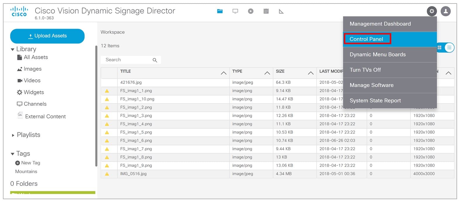
To configure local TV control, log into Cisco Vision Director as an Administrator. You will need to access the Control Panel and the Management Dashboard. Both are accessible from the Cisco Vision Director main page:
■![]() http://SV_Director_IP_addr:8080/Vision Director/
http://SV_Director_IP_addr:8080/Vision Director/
Figure 1 Cisco Vision Director Main Menu—Library
■![]() Go to Tools > Management Dashboard > Tools drawer > Advanced tab.
Go to Tools > Management Dashboard > Tools drawer > Advanced tab.
Configuring CUCM Integration
To enable communications between CUCM and Cisco Vision Director in support of luxury suite speed dials:
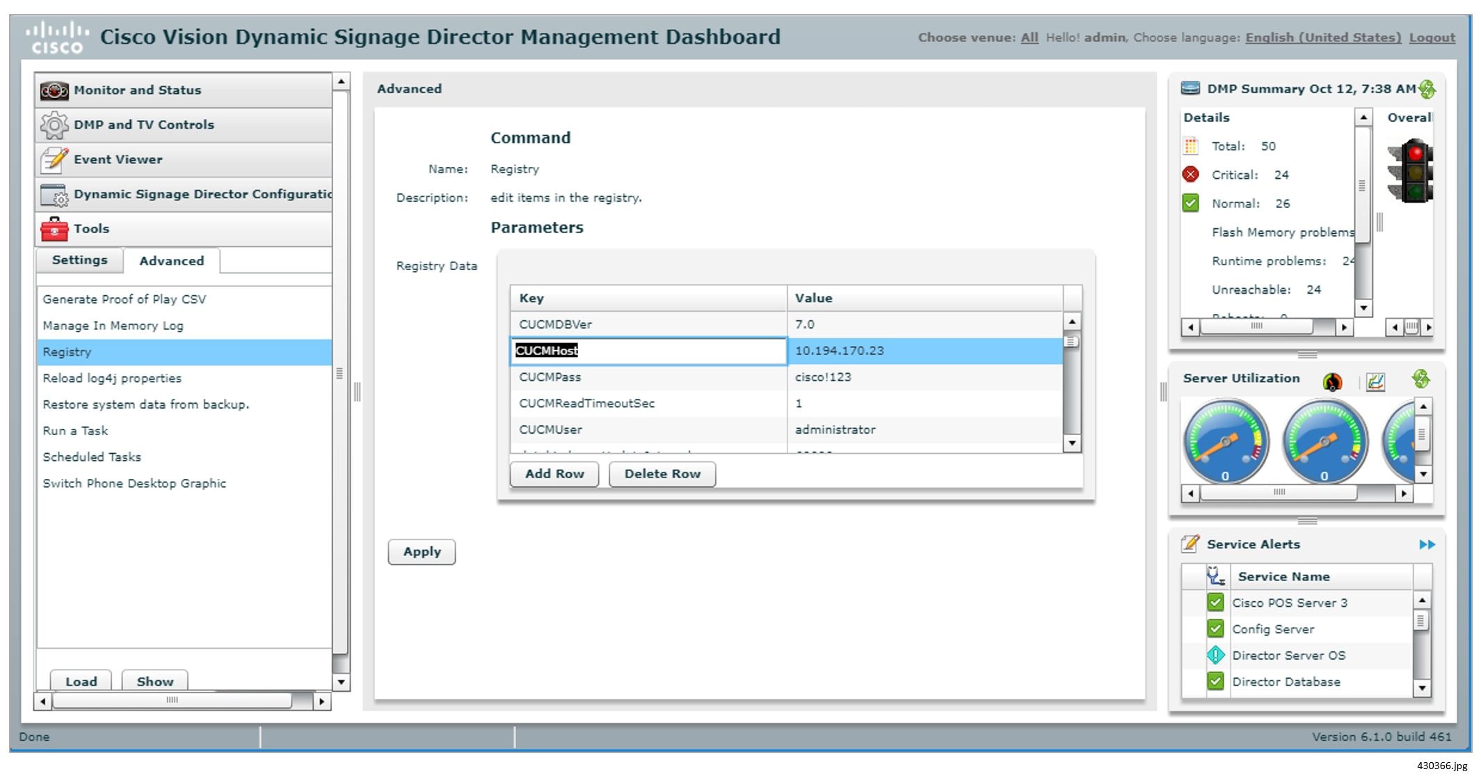
1.![]() Go to Tools > Management Dashboard > Tools drawer > Advanced tab > Registry.
Go to Tools > Management Dashboard > Tools drawer > Advanced tab > Registry.
2.![]() Click Load to ensure that you are viewing the current settings.
Click Load to ensure that you are viewing the current settings.
3.![]() Scroll through the Registry Data list to locate:
Scroll through the Registry Data list to locate:
Click the Value field for each and enter the appropriate information.
Notes: The registry entries are listed alphabetically, so the password (CUCMPass) is listed before the user ID (CUCMUser). Typically, user ID is followed by password, so enter the correct values for each. The CUCMUser that is used needs to be a CUCM Application User that is a member of the Standard TabSync User Group.
The CUCMHost value defaults to “localhost.” To use speed dials properly, this must be changed to the correct CUCM address. To disable the use of speed dials, set the CUCMHost registry entry to blank.
6.![]() Scroll through the registry data to locate: CUCMDBVer
Scroll through the registry data to locate: CUCMDBVer
7.![]() Click the Value field and enter the appropriate information. Valid values are as follows:
Click the Value field and enter the appropriate information. Valid values are as follows:
–![]() For CUCM version 7.1: enter 7.1
For CUCM version 7.1: enter 7.1
–![]() For CUCM version 8.6: enter 8.6
For CUCM version 8.6: enter 8.6
Restart Cisco Vision Director after saving the change to the value of the CUCMHost registry entry.
For more information about the Registry, see Release 6.1: Cisco Vision Dynamic Signage Director Operations Guide.
For more information about the correct CUCM db version to use, see AXL Versioning Support.
Setting IP Phone Passwords
Changing the phone desktop image requires that the phone's user ID and password be stored in Cisco Vision Director. Two ways exist to set the password in Cisco Vision Director.
If phones each have unique userid and passwords, enter the Admin ID and Admin Password on the Admin>Device>IP Phone page.
If all phones have the same password, store the username and password in the registry as follows:
1.![]() On the Advanced Tools page, click Registry.
On the Advanced Tools page, click Registry.
2.![]() Click Load to ensure that you are viewing the current settings.
Click Load to ensure that you are viewing the current settings.
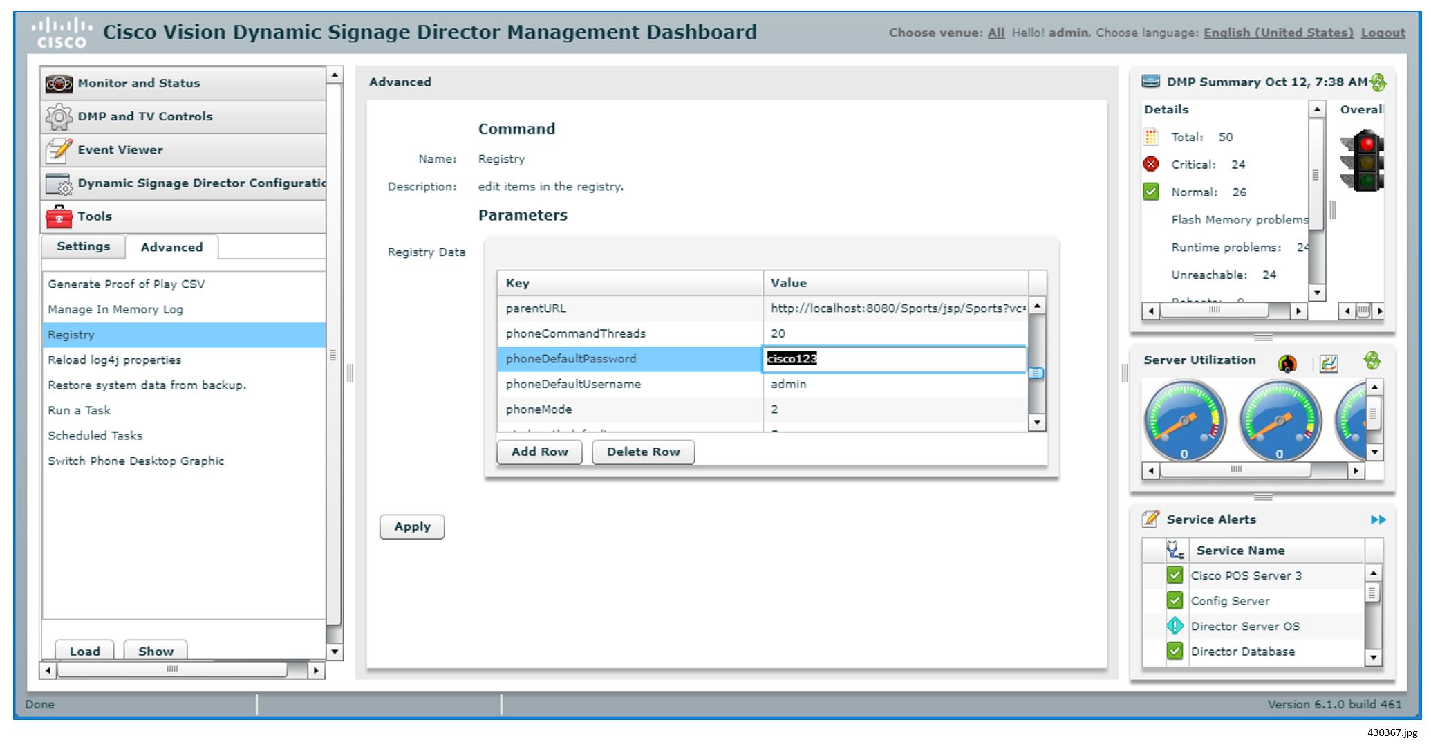
3.![]() Scroll through the Registry Data list to phoneDefaultPassword and phoneDefaultUsername.
Scroll through the Registry Data list to phoneDefaultPassword and phoneDefaultUsername.
4.![]() Click the Value field beside each parameter and enter the appropriate values.
Click the Value field beside each parameter and enter the appropriate values.
For more information about the Registry, see the Release 6.1: Cisco Vision Dynamic Signage Director Operations Guide.
Defining Local TV Control Devices in Cisco Vision Director
Before they can be associated with any designated area or any DMPs, all Cisco IP Phones and third- party control panels must be identified in Cisco Vision Director.
Defining Cisco IP Phones
To define a Cisco IP Phone in Cisco Vision Director:
1.![]() Go to Tools > Control Panel > Setup > Devices > IP P hone.
Go to Tools > Control Panel > Setup > Devices > IP P hone.
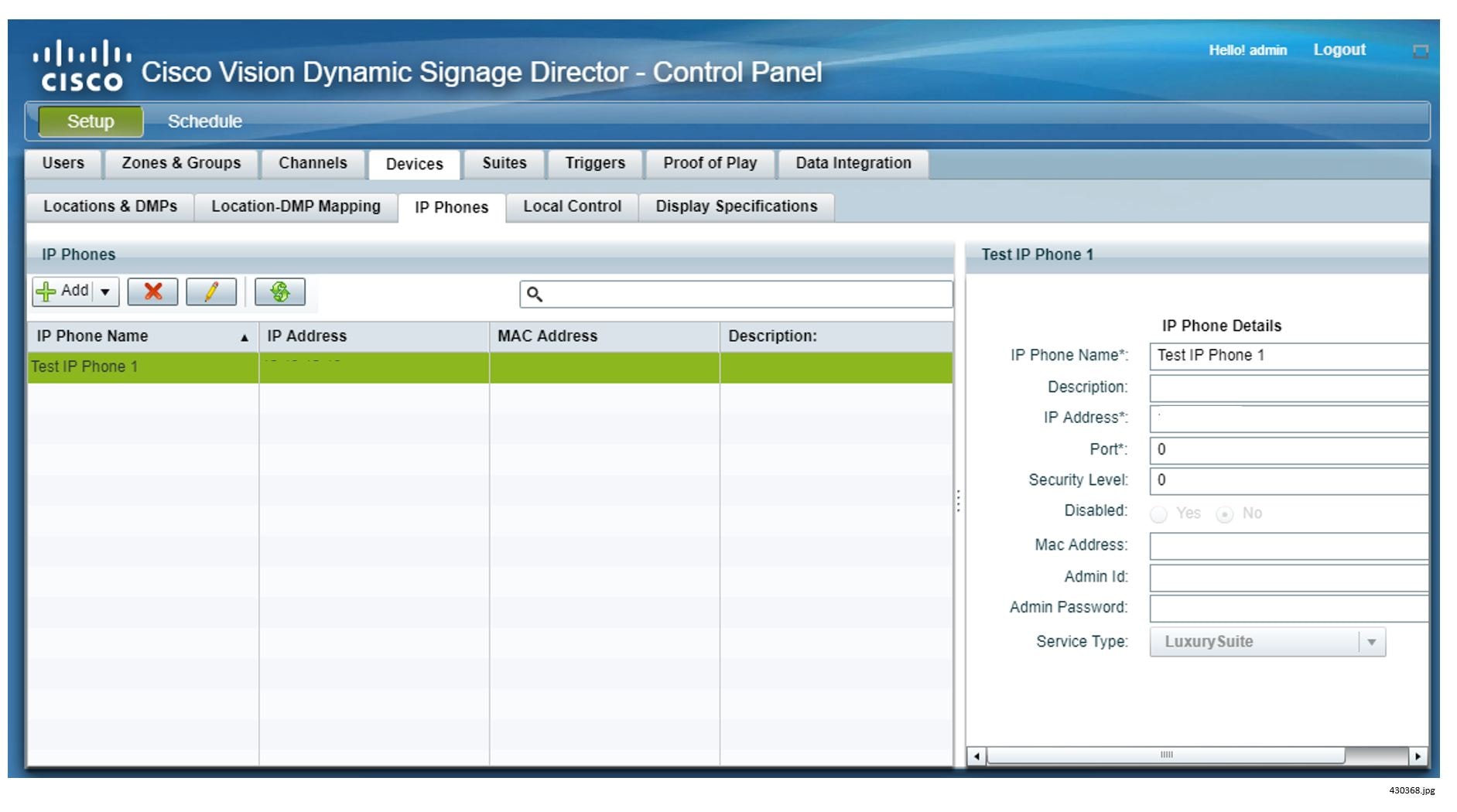
2.![]() To add a phone, click the + (plus sign) above the phone list.
To add a phone, click the + (plus sign) above the phone list.
3.![]() Under Phone Details, specify the following:
Under Phone Details, specify the following:
–![]() IP Phone Name: Name you wish to use to identify the phone within Cisco Vision Director.
IP Phone Name: Name you wish to use to identify the phone within Cisco Vision Director.
–![]() Description: Specify location of phone IP Address: IP address of the phone. Port: Do not change the port value.
Description: Specify location of phone IP Address: IP address of the phone. Port: Do not change the port value.
–![]() Security Level: Leave as default.
Security Level: Leave as default.
–![]() Disabled: To enable this phone as a control device select the Enable radio button.
Disabled: To enable this phone as a control device select the Enable radio button.
–![]() MAC Address: MAC Address of the phone.
MAC Address: MAC Address of the phone.
–![]() Admin ID/Password: The Admin ID and Password are specific to this phone. You need only specify these if this phone has unique credentials. Otherwise, the global phone credentials are specified in the registry using the Management Dashboard. See Setting IP Phone Passwords.
Admin ID/Password: The Admin ID and Password are specific to this phone. You need only specify these if this phone has unique credentials. Otherwise, the global phone credentials are specified in the registry using the Management Dashboard. See Setting IP Phone Passwords.
–![]() Service Type: Two types of services are available for the Cisco IP Phone:
Service Type: Two types of services are available for the Cisco IP Phone:
Luxury Suite service—which includes support for both Cisco Vision Director Video Services and Commerce Services.
Administrative Office service—which includes support for only the Cisco Vision Director Video Services. This is designed for use within administrative offices (and other locations where a Cisco IP Phone will be used for local TV control and commerce integration does not need to exist).
Changing the Service Type or Disabling Service on Multiple IP Phones
You can change the service type or disable Cisco Vision Director services on multiple IP phones:
1.![]() To select more than one IP Phone, press the Ctrl key while selecting each IP Phone. To select a consecutive group of IP Phones, press the Shift key and select the first and last desired IP Phone in the group.
To select more than one IP Phone, press the Ctrl key while selecting each IP Phone. To select a consecutive group of IP Phones, press the Shift key and select the first and last desired IP Phone in the group.
a.![]() Select the Disable radio button or
Select the Disable radio button or
Defining Third-Party Touch Panels
To define a third-party touch panel in Cisco Vision Director:
1.![]() Go to Tools > Control Panel > S etup.
Go to Tools > Control Panel > S etup.
2.![]() Click Devices > Local Control.
Click Devices > Local Control.
3.![]() To add a device, click the + (plus sign) above the list.
To add a device, click the + (plus sign) above the list.
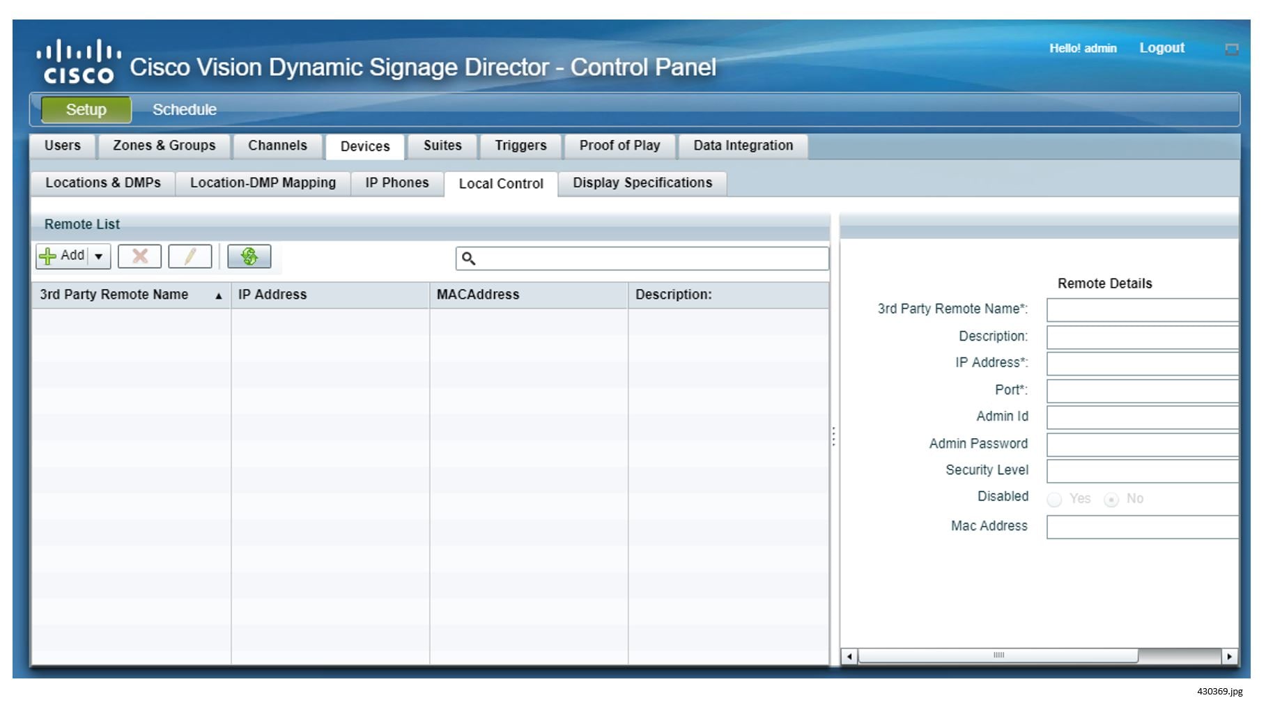
4.![]() Under Remote Details, enter the 3rd Party Remote Name and IP Address. Other fields are optional.
Under Remote Details, enter the 3rd Party Remote Name and IP Address. Other fields are optional.
Disabling Service on Multiple Third-Party Devices
You can change the service type or disable Cisco Vision Director services on multiple third-party devices:
1.![]() To select more than one third-party device, press the Ctrl key while selecting each device. To select a consecutive group of third-party devices, press the Shift key and select the first and last desired device in the group.
To select more than one third-party device, press the Ctrl key while selecting each device. To select a consecutive group of third-party devices, press the Shift key and select the first and last desired device in the group.
Defining Luxury Suites in Cisco Vision Director
The definition of a luxury suite in Cisco Vision Director includes one or more DMPs in a designated area and one Cisco IP Phone or third-party control panel for local control.
Note: Regardless of whether the designated area is a bar, club, restaurant, back office, press box, or luxury suite, it is defined in Cisco Vision Director using the Suites tab.
Configuring Basic Information
To define a local control area (suite, bar, restaurant, club, etc.):
1.![]() Go to Tools > Control Panel > Se tup.
Go to Tools > Control Panel > Se tup.
3.![]() To add a luxury suite, click the + (plus sign).
To add a luxury suite, click the + (plus sign).
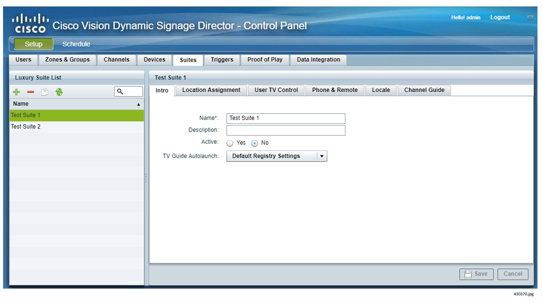
4.![]() On the Intro panel, enter the Name of the luxury suite (or designated area). Optionally, you can enter a description. Leave the Security Level at 99.
On the Intro panel, enter the Name of the luxury suite (or designated area). Optionally, you can enter a description. Leave the Security Level at 99.
Active determines whether services (such as TV control and ordering) are available in the suite. This provides a way for the venue to disable services on the phone during select events (such as preventing guests from changing channels on the TV during a concert).
TV Guide Autolaunch allows each suite to have a different TV Guide Autolaunch setting. The default is to use the setting in the registry. If the suite requires a different value than the registry, set it here.
Refer to Controlling the Behavior of the Channel Guide for details on the values.
Assigning DMPs to the Suite
To associate one or more DMPs with a luxury suite, restaurant, club or other designated area:
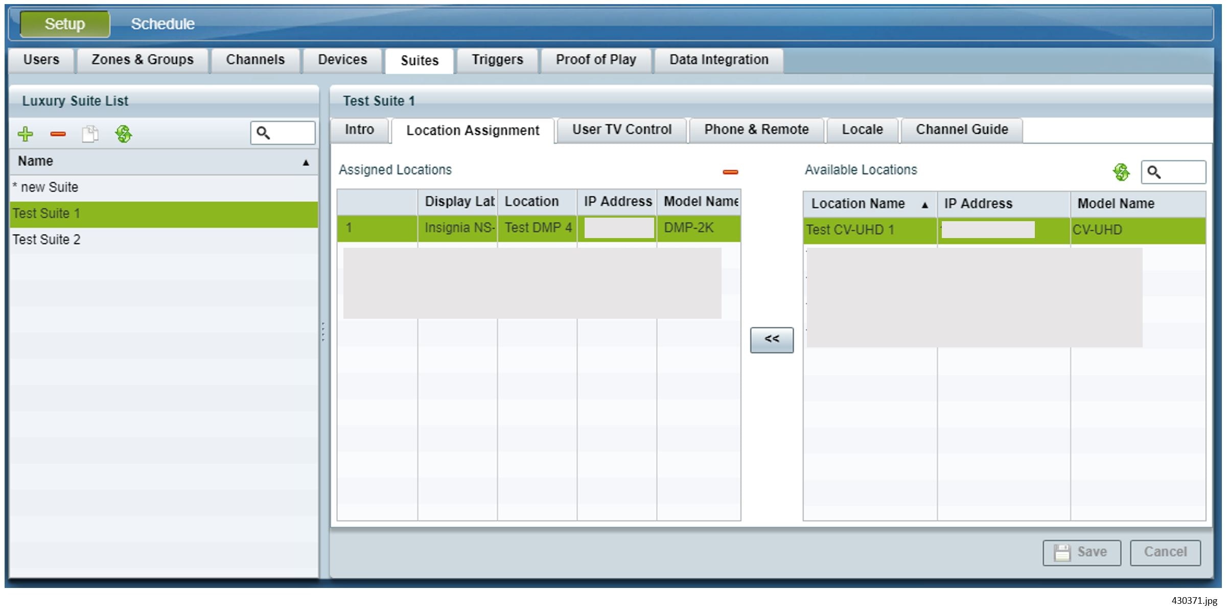
1.![]() Go to Tools > Control Panel > Setup > Suites > Locati on Assignment.
Go to Tools > Control Panel > Setup > Suites > Locati on Assignment.
2.![]() Select the desired DMPs from the list of Available DMPs. To select more than one DMP, press the Ctrl key while selecting each DMP. To select a consecutive group of DMPs, press the Shift key and select the first and last desired DMP in the group.
Select the desired DMPs from the list of Available DMPs. To select more than one DMP, press the Ctrl key while selecting each DMP. To select a consecutive group of DMPs, press the Shift key and select the first and last desired DMP in the group.
3.![]() Click the << button. The selected DMPs will be shown in the Assigned DMP list. Or, select and drag the desired DMPs from the Available DMPs list to the Assigned DMPs list.
Click the << button. The selected DMPs will be shown in the Assigned DMP list. Or, select and drag the desired DMPs from the Available DMPs list to the Assigned DMPs list.
The order of the DMPs in the list should reflect the order of the TVs in the local control area. The number associated with each will be used in the interface of the local TV control device to identify each TV. To change the order of the DMPs in the Assigned DMP list, simply select, drag, and drop into the correct position.
–![]() For luxury suites, the first DMP listed is considered the “designated TV.” This is the TV on which items are shown when placing an order if commerce integration is enabled.
For luxury suites, the first DMP listed is considered the “designated TV.” This is the TV on which items are shown when placing an order if commerce integration is enabled.
–![]() To remove a DMP from the Assigned list, select the desired DMP and click the “-” at the upper right of the Assigned DMPs box.
To remove a DMP from the Assigned list, select the desired DMP and click the “-” at the upper right of the Assigned DMPs box.
4.![]() For each added DMP, click in the field under the Display Label column and enter the desired label for the TV. The label defaults to the numeric position of DMP in the list. If the DMP list is re-ordered by using drag and drop, the numeric labels will be updated automatically. If the labels are edited to be a text label, re-ordering will not update the label.
For each added DMP, click in the field under the Display Label column and enter the desired label for the TV. The label defaults to the numeric position of DMP in the list. If the DMP list is re-ordered by using drag and drop, the numeric labels will be updated automatically. If the labels are edited to be a text label, re-ordering will not update the label.
This label will appear in the IP phone UI when a user selects TV/Volume. This label also appears on the TV when the TV identification banner is displayed.
Note: The identification banner is set in the DMP upon start-up. Therefore, changing the label requires a DMP flash template restart.
–![]() Never assign a DMP/Location to more than one Luxury Suite.
Never assign a DMP/Location to more than one Luxury Suite.
–![]() If an IP phone is configured in Cisco Vision Director, but not associated with a Luxury suite, an error message displays on the IP phone when the user attempts to access Cisco Vision Director services. The text of the error message is configured in the Cisco Vision Director Management Dashboard Registry using the “ipPhoneError.SuiteNotFound" parameter. If you modify the content of the message, ensure that carriage returns (represented by #) are placed in the appropriate places for the message to display correctly on the IP phone.
If an IP phone is configured in Cisco Vision Director, but not associated with a Luxury suite, an error message displays on the IP phone when the user attempts to access Cisco Vision Director services. The text of the error message is configured in the Cisco Vision Director Management Dashboard Registry using the “ipPhoneError.SuiteNotFound" parameter. If you modify the content of the message, ensure that carriage returns (represented by #) are placed in the appropriate places for the message to display correctly on the IP phone.
Adding a Local Control Device
To associate a local control device with a luxury suite, restaurant, club, or other designated area:
1.![]() Go to Tools > Control Panel > Setup > Suites > Phone and R emote.
Go to Tools > Control Panel > Setup > Suites > Phone and R emote.
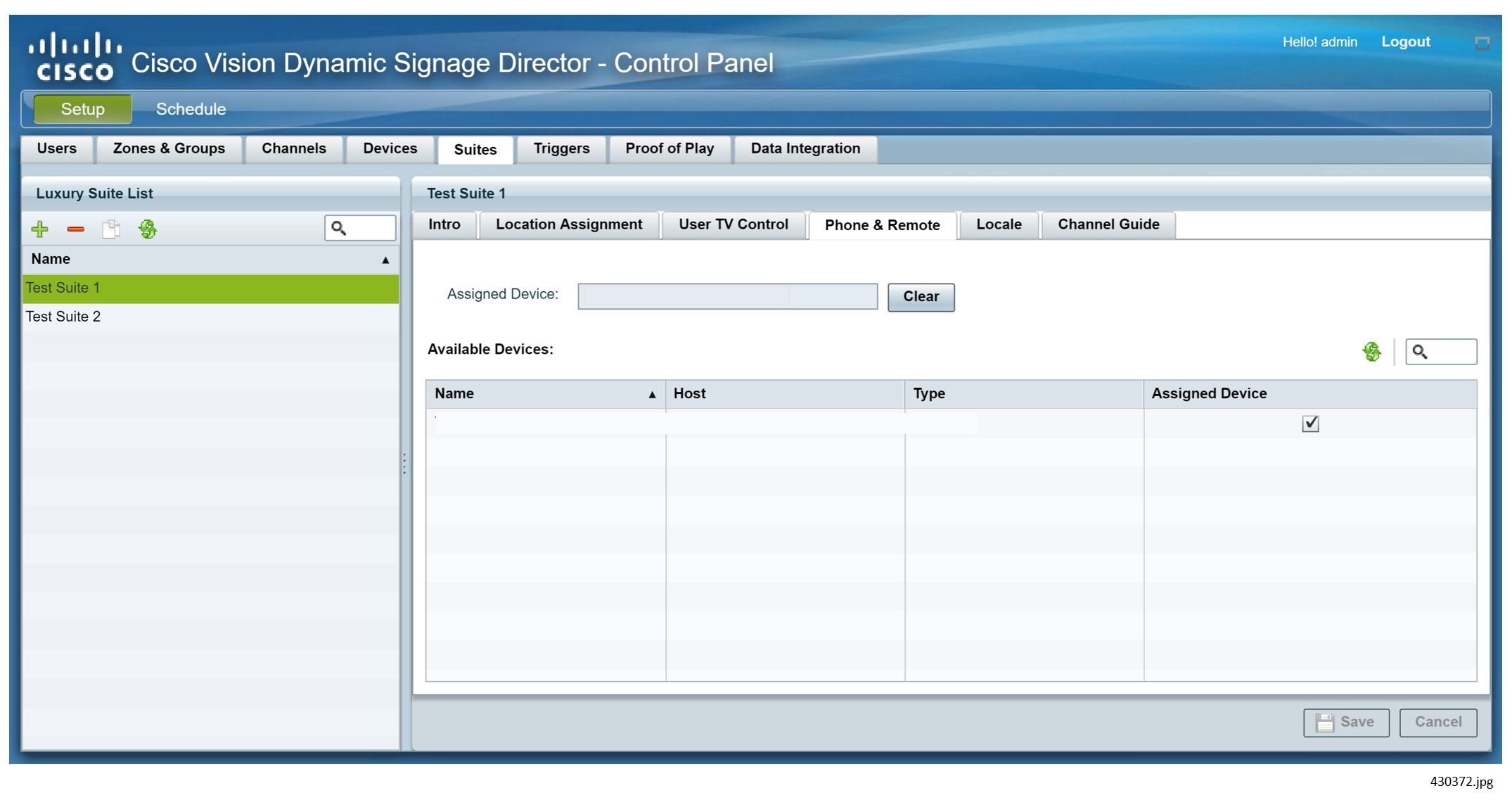
2.![]() Select the desired phone or 3rd party remote (as previously defined in Defining Local TV Control Devices in Cisco Vision Director).
Select the desired phone or 3rd party remote (as previously defined in Defining Local TV Control Devices in Cisco Vision Director).
Each IP phone or 3rd-party device can be assigned to only one “luxury suite” (that is, local control area). If the selected IP phone or 3rd-party remote is already assigned to another luxury suite, Cisco Vision Director will display a message prompting you to indicate whether you want to remove the device from the other luxury suite and re-assign it to this one.
Providing a Welcome Message on a Luxury Suite TV
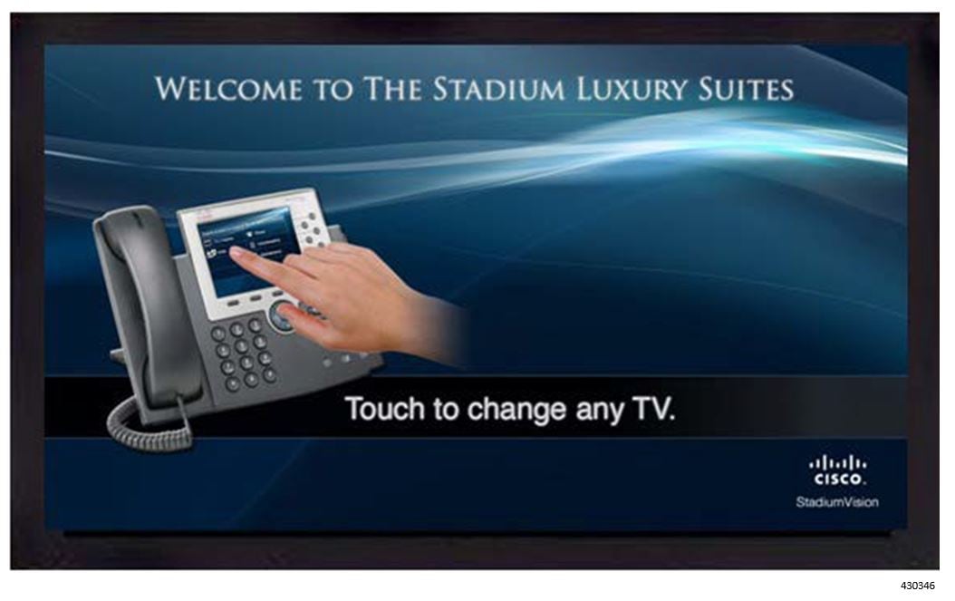
Typically, a single TV in the luxury suite will initially display a welcome message. Cisco Vision Director provides two example welcome message graphics (shown in Example Welcome Message) in Adobe Photoshop format.
Note : Welcome_SV2-1920 is for use with the DMPs. Refer to Release 6.1: Content Planning and Specification Guide: Dynamic Signage Director for details.
Figure 2 Example Welcome Message
For details on how to load content and create groups and playlists, refer to Release 6.1: Cisco Vision Dynamic Signage Director Operations Guide.
To implement a welcome message on a specific TV in a luxury suite:
1.![]() Open the supplied graphic in Adobe PhotoShop. Make modifications (as needed) and save the file as a.JPG.
Open the supplied graphic in Adobe PhotoShop. Make modifications (as needed) and save the file as a.JPG.
2.![]() Upload the.JPG into the Cisco Vision Director content Library.
Upload the.JPG into the Cisco Vision Director content Library.
3.![]() Place the DMPs associated with the welcome TVs in the desired luxury suites (typically one per suite) into a separate group.
Place the DMPs associated with the welcome TVs in the desired luxury suites (typically one per suite) into a separate group.
4.![]() Create a playlist using a full-screen graphic template and add the welcome message graphic to the playlist.
Create a playlist using a full-screen graphic template and add the welcome message graphic to the playlist.
Note: The template used for the Welcome message must be the Full-Screen Graphic template. Do not use an Overlay template.
5.![]() Associate the playlist with the group (created in Step 3) as part of a pre-game state.
Associate the playlist with the group (created in Step 3) as part of a pre-game state.
The welcome message will be displayed on the specified TV during the pre-game state until either the luxury suite guest changes the channel or there is a state change (from pre-game to in-game, for example).
Defining Channel Lineup (Guide)
The channels that make up the channel lineup for the entire venue are defined on the Channels panel of the Cisco Vision Director Setup page. The process for defining the master channel list and creating the default channel guide is described in the Cisco Vision Director Content and Event Management Design and Implementation Guide.
Leveraging the venue-wide master channel list, you can create per-area channel guides, which can be assigned to one or more luxury suites. The per-area channel guides are a subset of the master channel list, meaning the channels numbers and descriptions are preserved. If a DMP is not associated with a luxury suite, bar, restaurant, or other area that supports local control, then it will use the default channel guide.
Note: If you make changes to a channel guide that is associated with an area serviced by a third-party touch panel, the third-party device must reload the latest channel guide information. Consult the third-party device integrator (AMX or Crestron) for reload options.
To create a per-area channel guide and assign it to the desired luxury suites (after the master channel list has been created):
1.![]() Go to Tools > Control Panel > Setup > Channels > Channel Guide tab.
Go to Tools > Control Panel > Setup > Channels > Channel Guide tab.
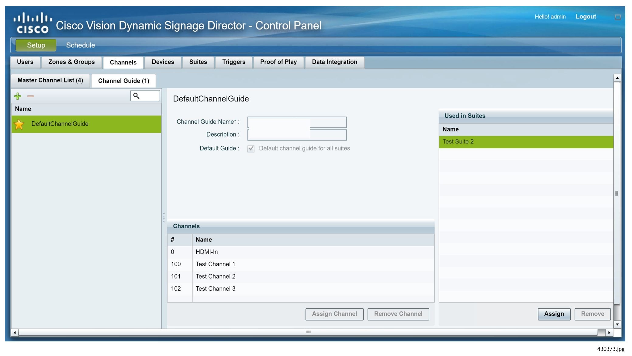
2.![]() To add a channel guide, click on the + (plus sign).
To add a channel guide, click on the + (plus sign).
3.![]() Specify the Channel Guide Name.
Specify the Channel Guide Name.
4.![]() Click Assign Channel. The master channel list displays.
Click Assign Channel. The master channel list displays.
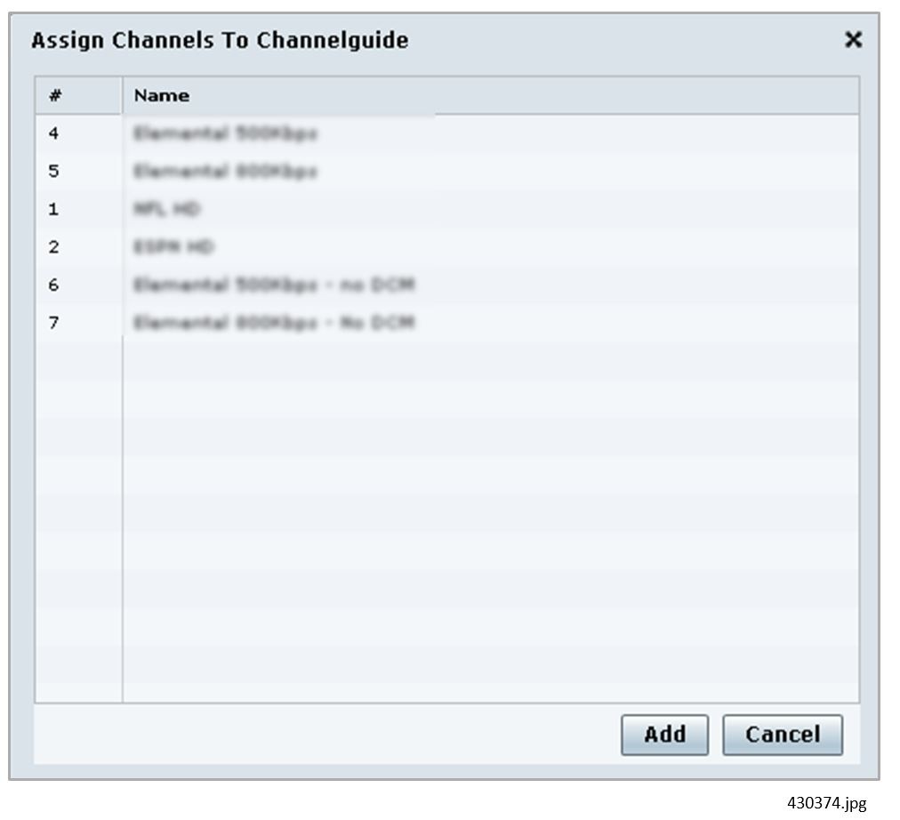
5.![]() Select the desired Channels from the list. To select more than one Channel, press the Ctrl key while selecting each Channel. To select a consecutive group of Channels, press the Shift key and select the first and last desired Channel.
Select the desired Channels from the list. To select more than one Channel, press the Ctrl key while selecting each Channel. To select a consecutive group of Channels, press the Shift key and select the first and last desired Channel.
7.![]() Click Assign (under the “Used in Suites” list. The list of configured Luxury Suites displays.
Click Assign (under the “Used in Suites” list. The list of configured Luxury Suites displays.
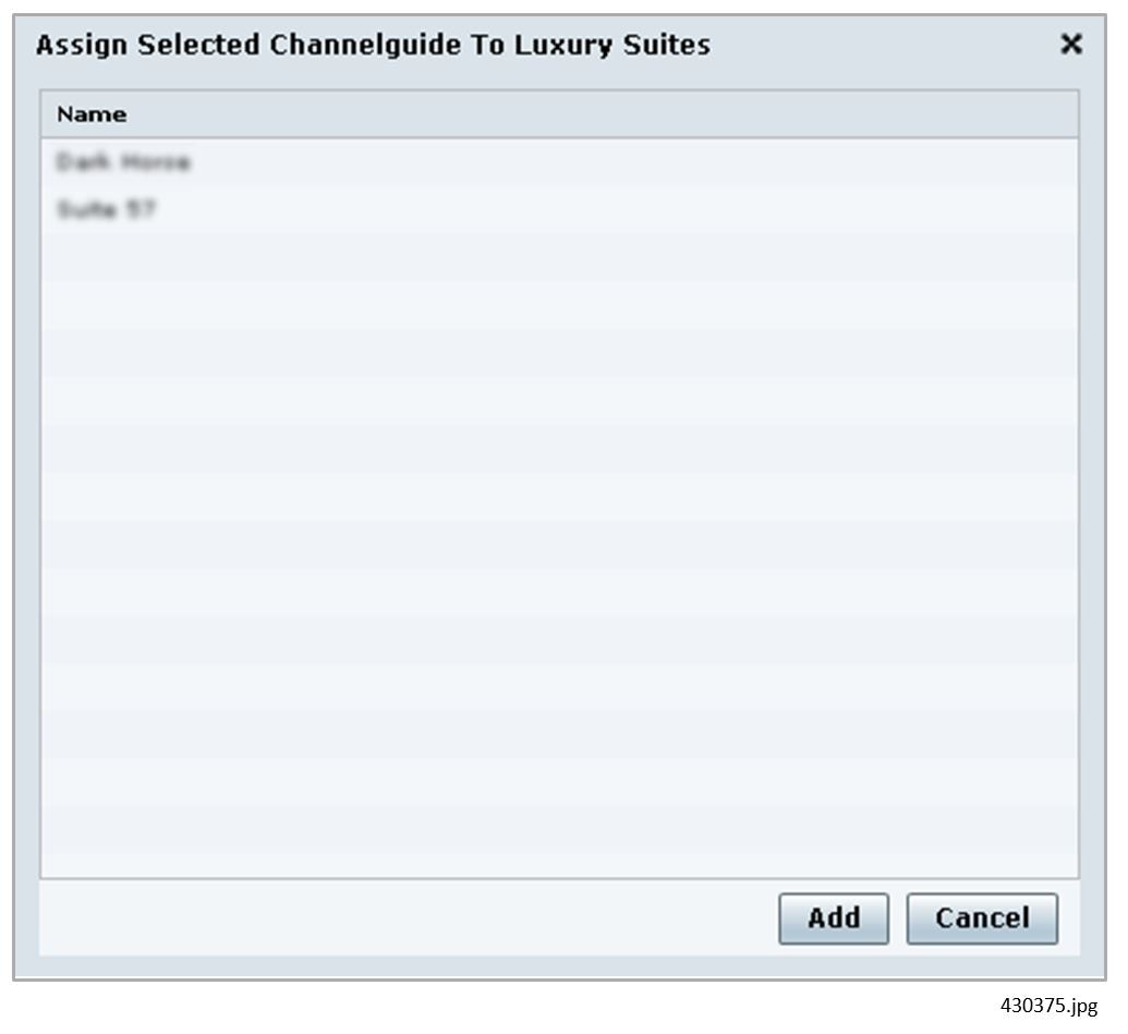
8.![]() Select the desired Suites from the list. To select more than one Suite, press the Ctrl key while selecting each Suite. To select a consecutive group of Suite, press the Shift key and select the first and last desired Suite.
Select the desired Suites from the list. To select more than one Suite, press the Ctrl key while selecting each Suite. To select a consecutive group of Suite, press the Shift key and select the first and last desired Suite.
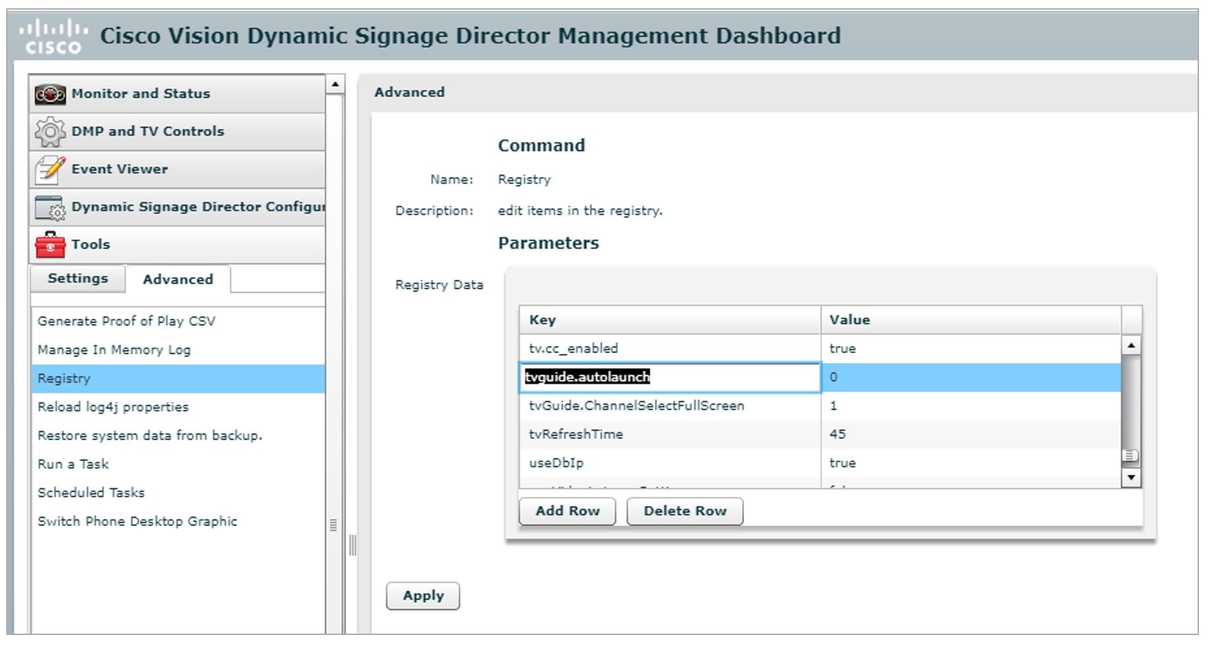
By default, when the channel guide is brought up on the IP Phone, it is also displayed on the selected TV(s). You can change this behavior by setting the “tvguide.autolaunch” parameter to 0 in the Cisco Vision Director Management Dashboard Registry. Go to Tools > Management Dashboard > Tools drawer > Advanced tab > Registry (Figure 3).
Figure 3 TVGuide Autolaunch in Registry
Using “Favorites” (AMX or Crestron Touch Panels Only)
In addition to the channel lineup, a maximum of 10 channels can be identified as favorites, which appear on the initial video control page of the third-party touch panels.
For each channel that should be listed as a favorite:
■![]() In the Favorite field, select Yes.
In the Favorite field, select Yes.
■![]() In the Favorite Order field, enter a number (between 1 and 10) indicating the ordinal placement of this channel in the listing.
In the Favorite Order field, enter a number (between 1 and 10) indicating the ordinal placement of this channel in the listing.
Work with the third-party device integrator to determine how the favorites list should be displayed on the third-party touch panels. All installations should move to access channels directly versus indirectly through the favorites mechanism.
Controlling the Behavior of the Channel Guide
The appearance and behavior of the channel guide are controlled by parameters in the Cisco Vision Director registry (Figure 3).
The registry settings are as follows:
"tvGuide.ChannelSelectFullScreen
This parameter controls whether the selected channel is displayed in full-screen mode. The default is tvGuide.ChannelSelect FullScreen = 1.
If the tvGuide.ChannelSelectFullScreen = 1 and the guide is displayed on the TV, then when a user selects a channel, the selected channel is displayed in full-screen mode on the TV.
If the tvGuide.ChannelSelectFullScreen = 0 and the guide is displayed on the TV, when a user selects a channel, the guide preview window will change but the user must navigate away from the channel select page (by moving to the Home Page, Display Select Page, Exit, etc.) for the selected channel to be displayed in full-screen mode on the TV.
This parameter controls whether the channel guide is automatically displayed on the TV when the display is selected. The default is tvguide.autolaunch = 1. (This will change in subsequent releases.)
If tvguide.autolaunch = 0, do not automatically display the guide.
If tvguide.autolaunch = 1, automatically display the guide.
Note: This parameter can be overridden for an individual suite at the Luxury Suite Basic Info panel in the Control Panel.
"phoneControl.stayOnChannelSelect
This parameter controls whether the IP Phone continues to show the channel guide after the user has made their selection. The default is phoneControl.stayOnChannelSelect = 1. This registry parameter must be added.
If the phoneControl.stayOnChannelSelect = 0, the IP Phone will go back to previous page after the user selects a channel.
If the phoneControl.stayOnChannelSelect = 1, the IP Phone will continue to display the channel guide after the user selects a channel.
The following table indicates how the settings for these three parameters interact to produce a specific behavior.
To set the values of these parameters:
1.![]() Go to Tools > Management Dashboard > Tools drawer > Advanced tab > Registry.
Go to Tools > Management Dashboard > Tools drawer > Advanced tab > Registry.
2.![]() Click Load to ensure that you are viewing the current settings.
Click Load to ensure that you are viewing the current settings.
3.![]() Scroll through the Registry Data list to the desired parameters.
Scroll through the Registry Data list to the desired parameters.
Note : To change the phoneControl.stayOnChannelSelect parameter from its default (1), add the parameter using Add Row.
4.![]() Click the Value field beside each parameter and enter the appropriate values.
Click the Value field beside each parameter and enter the appropriate values.
For more information about the Registry, see Release 6.1: Cisco Vision Dynamic Signage Director Operations Guide.
Changing the IP Phone Background
Once an alternative background has been loaded in CUCM (as described in the section on Loading the Cisco Vision Director IP Phone Desktop Graphic), you can use Cisco Vision Director to change the background on the Cisco IP Phone.
Note: Use this feature to change the desktop graphic to the official Cisco Vision Director graphic. Be careful changing the desktop graphic to any other image; the result may be undesirable.
1.![]() Go to Tools > Management Dashboard > Tools drawer > Advanced tab > Switch Phone Desktop Graphic.
Go to Tools > Management Dashboard > Tools drawer > Advanced tab > Switch Phone Desktop Graphic.
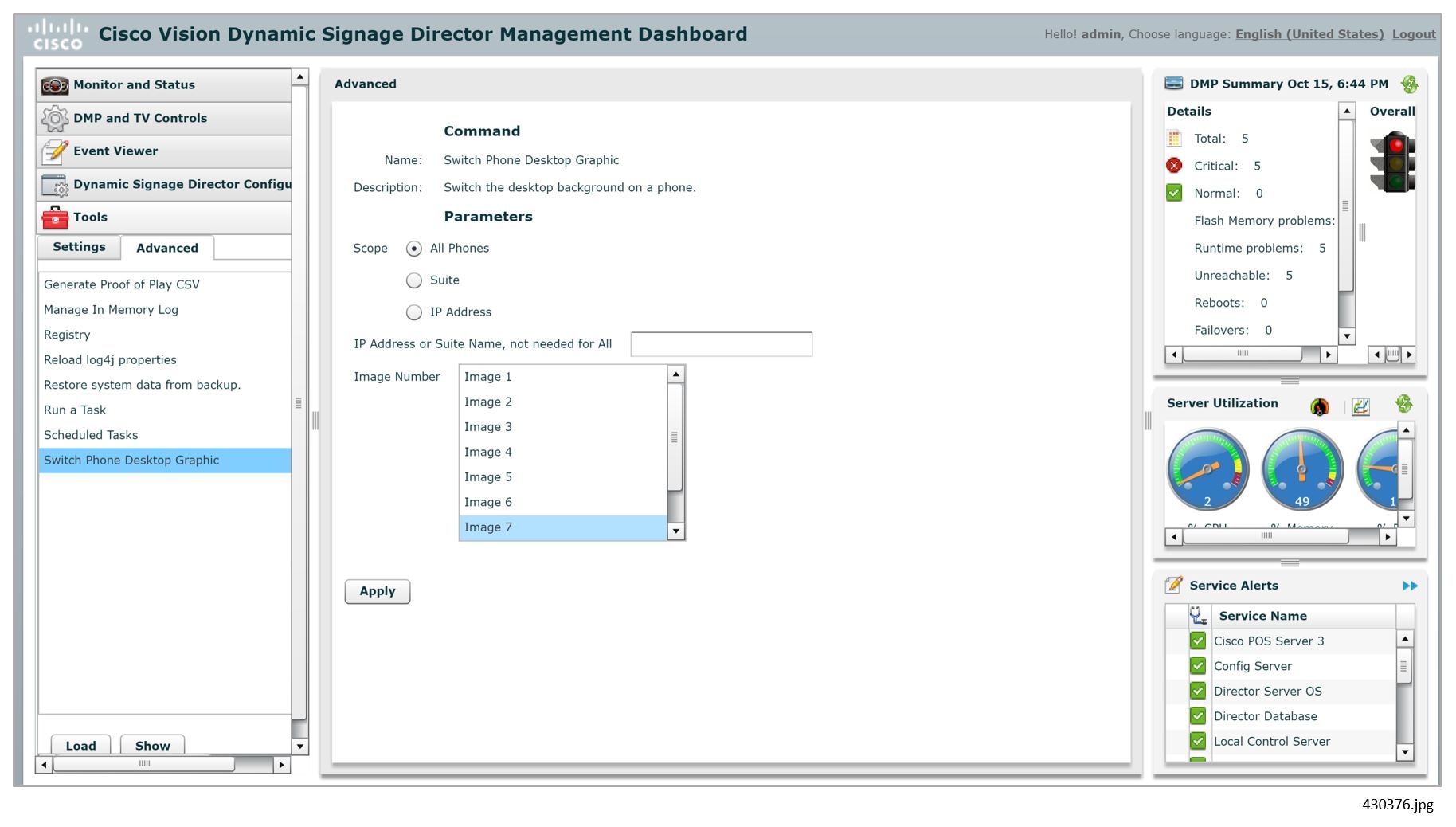
If you select Suite, specify the Ext. Suite ID configured on the Setup > Luxury Suite > Commerce Integration tab. If the venue does not use commerce integration, use the IP Address parameter to narrow the scope.
If you select IP Address, enter the address of the IP Phone.
Cisco Vision Director supports up to nine images, even though the CUCM supports more.
Image 1 is the factory-default image (which cannot be customized.) Images 2 through 9 correspond to the order of the images in the List.xml file (which is loaded into CUCM).
The Image Number list always includes Image 1 through Image 9. The list does not change even if there is only one image in CUCM, or there are more than nine.
If an image number is selected that is greater than the amount of images available in the CUCM, the factory default image (Image 1) will be used.
It takes approximately 10 seconds for the background switch to take effect on a single phone. Changes to multiple phones will be processed serially; for example, when choosing option 'All'. Note that the phone background change is visible on the phone while it is occurring (you can see screen navigation as it occurs).
For more information about the Advanced Tools, see Release 6.1: Cisco Vision Dynamic Signage Director Operations Guide.
Adjusting IP Phone Timeout Values
When guests use the IP Phone for local TV control or ordering, if the IP Phone receives no input from the guest for a given amount of time (is idle), it returns to the home page. By default, the idle timeout is set to 30 seconds.
1.![]() Go to Tools > Management Dashboard > Tools drawer > Advanced tab > Registry.
Go to Tools > Management Dashboard > Tools drawer > Advanced tab > Registry.
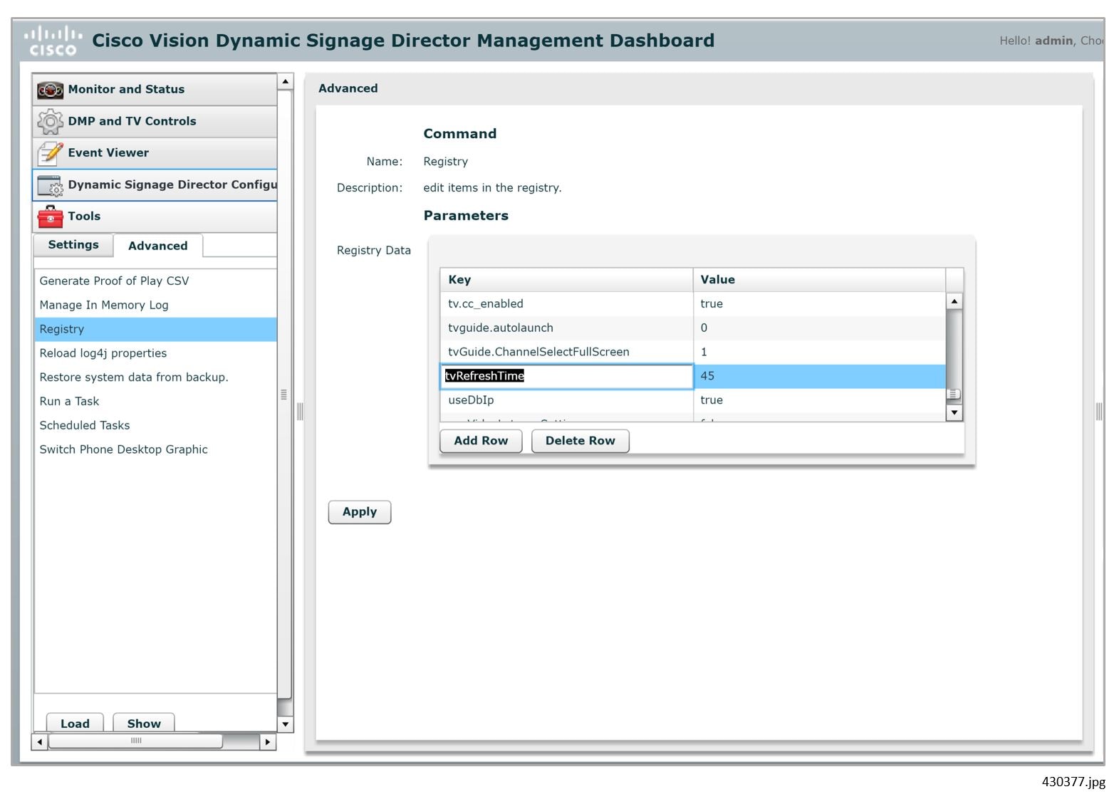
2.![]() Click Load to ensure that you are viewing the current settings.
Click Load to ensure that you are viewing the current settings.
3.![]() Scroll through the Registry Data list to tvRefreshTime (to modify the idle timeout for TV control) and to orderRefreshTime (to modify the idle timeout for ordering).
Scroll through the Registry Data list to tvRefreshTime (to modify the idle timeout for TV control) and to orderRefreshTime (to modify the idle timeout for ordering).
4.![]() Click in the Value field beside each and enter the new idle timeout in seconds.
Click in the Value field beside each and enter the new idle timeout in seconds.
For more information about the Registry, see Release 6.1: Cisco Vision Dynamic Signage Director Operations Guide.
Labeling TV External Inputs
In a luxury suite, guests can use the Cisco IP Phone to change the TV input to an external device, such as a DVD player. To make it easier for the guest to select the input, do the following to label the TV's external inputs in Cisco Vision Director:
1.![]() Go to Tools > Control Panel > Setup > Devices > Display Specifications.
Go to Tools > Control Panel > Setup > Devices > Display Specifications.
2.![]() Select the desired device (TV) and click Display Parameters.
Select the desired device (TV) and click Display Parameters.
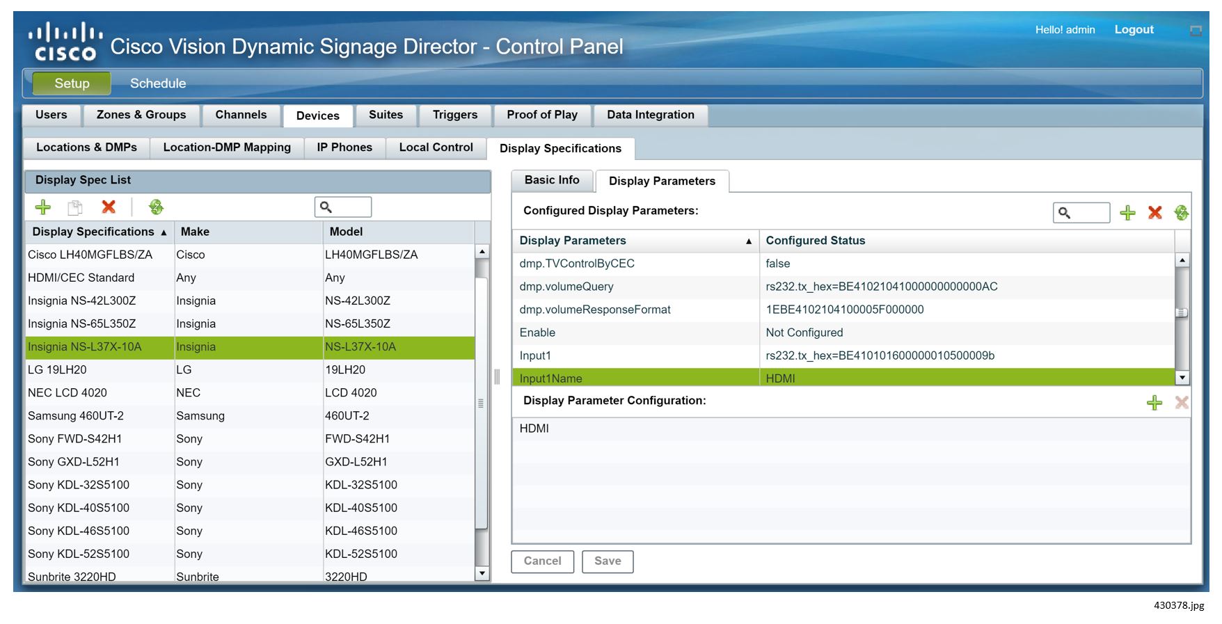
3.![]() For each desired input (1 through 4):
For each desired input (1 through 4):
a.![]() Select the InputxName command in the available list and click << to add it to the configured list.
Select the InputxName command in the available list and click << to add it to the configured list.
b.![]() Select the InputxName command in the configured list and click + at the upper right of the Serial Strings of Selected Commands. Enter the desired label, such as HDMI or Composite. This label appear on the Cisco IP Phone when the guest selects the Advanced option.
Select the InputxName command in the configured list and click + at the upper right of the Serial Strings of Selected Commands. Enter the desired label, such as HDMI or Composite. This label appear on the Cisco IP Phone when the guest selects the Advanced option.
c.![]() Select the Inputx command in the available list and click << to add it to the configured list.
Select the Inputx command in the available list and click << to add it to the configured list.
d.![]() Select the Inputx command in the configured list and click + at the upper right of the Serial Strings of Selected Commands. Enter the appropriate RS-232 command for that input.
Select the Inputx command in the configured list and click + at the upper right of the Serial Strings of Selected Commands. Enter the appropriate RS-232 command for that input.
4.![]() If the TV has more available inputs:
If the TV has more available inputs:
a.![]() Click + at the upper right of the Available Serial Commands box and add a corresponding command called InputxName, where x is a number that identifies the input.
Click + at the upper right of the Available Serial Commands box and add a corresponding command called InputxName, where x is a number that identifies the input.
b.![]() Select the InputxName command in the available list and click << to add it to the configured list.
Select the InputxName command in the available list and click << to add it to the configured list.
c.![]() Select the InputxName command in the configured list and click + at the upper right of the Serial Strings of Selected Commands. Enter the desired label.
Select the InputxName command in the configured list and click + at the upper right of the Serial Strings of Selected Commands. Enter the desired label.
d.![]() Click + at the upper right of the Available Serial Commands box and add a corresponding command called Inputx, where x is the number that identifies the input.
Click + at the upper right of the Available Serial Commands box and add a corresponding command called Inputx, where x is the number that identifies the input.
e.![]() Select the Inputx command in the available list and click << to add it to the configured list.
Select the Inputx command in the available list and click << to add it to the configured list.
f.![]() Select the Inputx command in the configured list and click + at the upper right of the Serial Strings of Selected Commands. Enter the appropriate RS-232 command for that input.
Select the Inputx command in the configured list and click + at the upper right of the Serial Strings of Selected Commands. Enter the appropriate RS-232 command for that input.
 Feedback