Switch Models
|
License Level |
Description |
|
|---|---|---|
|
IE-3500H-8T-E |
Network Essentials |
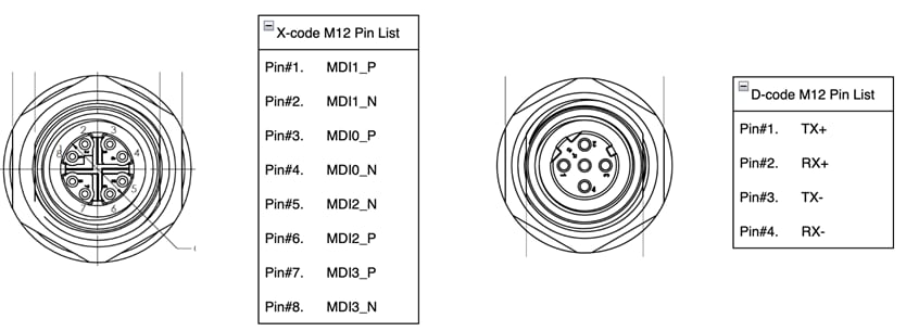
8x 10/100/1G X-code M12 ports, non-PoE |
|
IE-3500H-16T-E |
Network Essentials |
16x 10/100/1G X-code M12 ports, non-PoE |
|
IE-3500H-24T-E |
Network Essentials |
24x 10/100/1G X-code M12 ports, non-PoE |
|
IE-3500H-12FT4T-E |
Network Essentials |
12x 10/100 D-code M12 ports, 4x 10/100/1G X-code M12 ports, non-PoE |
|
IE-3500H-20FT4T-E |
Network Essentials |
20x 10/100 D-code M12 ports, 4x 10/100/1G X-code M12 ports, non-PoE |
|
IE-3500H-14P2T-E |
Network Essentials |
14x 10/100/1G X-code PoE/PoE+ ports, 2x 10/100/1G X-Code M12 ports, PoE power budget of 240 W |
|
IE-3500H-12P2MU2X-E |
Network Essentials |
2x 10G SFP+ ports, 2x 100/1G/2.5G UPoE X-code ports, 12x 10/100/1G M12 X-code ports, PoE power budget of 240 W |
|
IE-3505H-16T-E |
Network Essentials |
16x 10/100/1G X-code M12 ports, non-PoE |
|
IE-3500H-8T-A |
Network Advantage |
8x 10/100/1G X-code M12 ports, non-PoE |
|
IE-3500H-16T-A |
Network Advantage |
16x 10/100/1G X-code M12 ports, non-PoE |
|
IE-3500H-24T-A |
Network Advantage |
24x 10/100/1G X-code M12 ports, non-PoE |
|
IE-3500H-12FT4T-A |
Network Advantage |
12x 10/100 D-code M12 ports, 4x 10/100/1G X-code M12 ports, non-PoE |
|
IE-3500H-20FT4T-A |
Network Advantage |
20x 10/100 D-code M12 ports, 4x 10/100/1G X-code M12 ports, non-PoE |
|
IE-3500H-14P2T-A |
Network Advantage |
14x 10/100/1G X-code PoE/PoE+ ports, 2x 10/100/1G X-Code M12 ports, PoE power budget of 240 W |
|
IE-3500H-12P2MU2X-A |
Network Advantage |
2x 10G SFP+ ports, 2x 100/1G/2.5G UPoE X-code ports, 12x 10/100/1G M12 X-code ports, PoE power budget of 240 W |
|
IE-3505H-16T-A |
Network Advantage |
16x 10/100/1G X-code M12 ports, non-PoE |
|
Specifications |
All PIDs |
|---|---|
|
Removable storage |
SD card1 |
|
Alarm2,3 |
1 alarm output relay 1 alarm input relay |
|
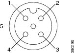
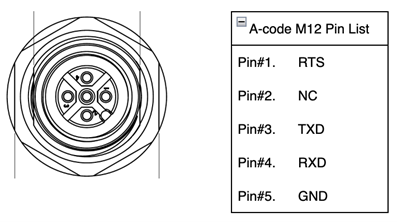
Console port2 |
1 |
-
The SD card is optional and is not shipped by default with the switch.
-
Using an M12 A-coded 5-pin connector.
-
Relay max. rating: 24Vdc at 1A, 48Vdc at 0.5A.


 Feedback