Switch Installation

This chapter describes how to install your switch and connect the switch to other devices. It also includes information specifically for installations in hazardous environments.

We recommend performing a preliminary configuration of the switch before it is installed in a permanent location.

Preparing for Installation

Warnings

These warnings are translated into several languages in the Regulatory Compliance and Safety Information for this switch.


Warning


Statement 1003—DC Power Disconnection

To reduce risk of electric shock or personal injury, disconnect DC power before removing or replacing components or performing upgrades.


Warning


Statement 1017—Restricted Area

This unit is intended for installation in restricted access areas. Only skilled, instructed, or qualified personnel can access a restricted access area.


Warning


Statement 1024—Ground Conductor

This equipment must be grounded. To reduce the risk of electric shock, never defeat the ground conductor or operate the equipment in the absence of a suitably installed ground conductor. Contact the appropriate electrical inspection authority or an electrician if you are uncertain that suitable grounding is available.


Warning


Statement 1033—Safety Extra-Low Voltage (SELV)—IEC 60950/ES1–IEC 62368 DC Power Supply

To reduce the risk of electric shock, connect the unit only to a DC power source that complies with the SELV requirements in the IEC 60950-based safety standards or the ES1 requirements in the IEC 62368-based safety standards.


Warning


Statement 1074—Comply with Local and National Electrical Codes

To reduce risk of electric shock or fire, installation of the equipment must comply with local and national electrical codes.


Warning


Statement 1079—Hot Surface

This icon is a hot surface warning. To avoid personal injury, do not touch without proper protection.


Note


Statement 1089—Instructed and Skilled Person Definitions

An instructed person is someone who has been instructed and trained by a skilled person and takes the necessary precautions when working with equipment.

A skilled person or qualified personnel is someone who has training or experience in the equipment technology and understands potential hazards when working with equipment.


Warning


Statement 1091—Installation by an Instructed Person

Only an instructed person or skilled person should be allowed to install, replace, or service this equipment. See statement 1089 for the definition of an instructed or skilled person.


Warning


Statement 9001—Product Disposal

Ultimate disposal of this product should be handled according to all national laws and regulations.


Caution


Airflow around the switch must be unrestricted. To prevent the switch from overheating, there must be the following minimum clearances:– Top and bottom: 1.0 in. (25 mm)– Sides: 1.0 in. (25 mm)– Front: 1.0 in. (25 mm)


Caution


If the installer is providing cabling for an IP66/IP67 and Type 4X rated environment, the cables must be suitably rated for IP66/IP67 and Type 4X requirements


EMC Environmental Conditions for Products Installed in the European Union

This section applies to products to be installed in the European Union.

The equipment is intended to operate under the following environmental conditions with respect to EMC:

  • A separate defined location under the user’s control.

  • Earthing and bonding shall meet the requirements of ETS 300 253 or CCITT K27.

  • AC-power distribution shall be one of the following types, where applicable: TN-S and TN-C as defined in IEC 364-3.


    Note


    When used with an AC power supply.

In addition, if equipment is operated in a domestic environment, interference could occur.

Installation Guidelines

When determining where to place the switch, observe these guidelines.

Environment and Enclosure Guidelines

Review these environmental and enclosure guidelines before installation:

  • This equipment is considered Group 1, Class A industrial equipment, according to IEC/CISPR Publication 11. Without appropriate precautions, there may be potential difficulties ensuring electromagnetic compatibility in other environments due to conducted as well as radiated disturbance.


Caution


To meet IP67 Compliance, all cables, dust caps, or the captive screws on the SD card cover must be torqued to the recommended spec before operating the unit.


Caution


Use caution when removing dust caps. Dust caps in an over-tightened state may adhere to the connector O-ring seal. Ensure that the O-ring remains in place when dust caps are removed and follow all torque specifications from Torque Specifications.


General Guidelines

Before installation, observe these general guidelines:


Caution


Proper ESD protection is required whenever you handle Cisco equipment. Installation and maintenance personnel should be properly grounded by using ground straps to eliminate the risk of ESD damage to the switch. Do not touch connectors or pins on component boards. Do not touch circuit components inside the switch. When not in use, store the equipment in appropriate static-safe packaging.


  • If you are responsible for the application of safety-related programmable electronic systems (PES), you need to be aware of the safety requirements in the application of the system and be trained in using the system.

When determining where to place the switch, observe these guidelines:

  • Before installing the switch, first verify that the switch is operational by powering it on and observing boot fast.

  • For 10/100 ports and 10/100/1000/2500 ports, the cable length from a switch to an attached device cannot exceed 328 feet (100 meters).

    The 10GE SFP+ transceiver module determines the supported maximum cable length for 10G ports.

  • Operating environment is within the ranges listed in Technical Specifications.

  • Clearance to front and rear panels meets these conditions:

    • Front-panel LEDs can be easily read.

    • Access to ports is sufficient for unrestricted cabling.

    • Front-panel direct current (DC) power connectors and the alarm connector are within reach of the connection to the DC power source.

  • Airflow around the switch must be unrestricted. To prevent the switch from overheating, you must have the following minimum clearances:

    • Top and bottom: 1.0 in. (25 mm)

    • Sides: 1.0 in. (25 mm)

    • Front: 1.0 in. (25 mm)

  • Ambient temperature does not exceed 140°F (60°C).

  • For optimal signal integrity, you must adjust the distance between cables and electrical noise sources (such as radios, power lines, and fluorescent lighting) based on the magnitude of the noise.

Verifying Package Contents

The box contains the following items.

  • The Cisco switch with a pre-installed mounting bracket

  • Pointer card

Tools and Equipment

Obtain these necessary tools and equipment:

  • A single or a pair of stud-size 6 ring terminals (Hollingsworth part number R3456B or equivalent) for use as a protective ground connector.

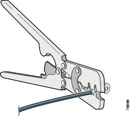
  • Crimping tool (Thomas & Bett part number WT2000, ERG-2001 or equivalent).

  • 6 AWG copper ground wire.

  • UL- and CSA-rated, style 1007 or 1569 twisted-pair copper appliance wiring material (AWM) wire for DC power connections.

  • Wire-stripping tool for stripping wires.

  • Screws to mount the switch. (Not supplied.)


    Note


    The screw type and size depend on the mounting material and building codes.
  • Number-2 Phillips screwdriver.

  • Flat-blade screwdriver.

  • 15mm 12-point socket for IP67 dust caps

  • Torque Driver (Such as a Torqueleader TT500 or equivalent)

Mounting the Switch


Caution


To prevent the switch from overheating, ensure these minimum clearances:– Top and bottom: 1.0 in. (25 mm)– Exposed side (not connected to the module): 1.0 in. (25 mm) – Front: 1.0 in. (25 mm)


Installing the Switch on the Wall


Warning


Statement 1094—Read Wall-Mounting Instructions Before Installation

Read the wall-mounting instructions carefully before beginning installation. Failure to use the correct hardware or to follow the correct procedures could result in a hazardous situation to people and damage to the system.


Procedure


Step 1

Position the switch mounting bracket against the wall or a panel in the desired location, with the arrow pointing up. See the following figure. Attach the bracket to the wall with the 4 enclosed Phillips screws.

Figure 1. Mounting Wall Bracket to Wall

Note

 
When attaching the bracket to the wall or panel, ensure that the screws engage a stud or support structure capable of supporting the weight of the bracket and the switch.

Step 2

Loosely attach the 4 mounting screws to the switch and slide it into the bracket and down. See the following figure.

Figure 2. Attaching the Switch to the Mounting Bracket

Step 3

To remove the switch, loosen the 4 mounting screws and slide the switch up and forward, out of the mounting bracket. Then the bracket itself can be unscrewed from the wall, if necessary.


What to do next

After the switch is mounted on the wall or panel, connect the power and alarm wires, as described in the Connecting Alarm Circuits.

Installing or Removing the Memory Card (Optional)

The switch supports a hot-swappable SD memory card. The firmware and startup configuration are stored on the card, which makes it possible to replace a failed switch without reconfiguring the replacement.

The SD memory card cover protects the flash card against shock and vibration by holding the card in place. The cover is attached with a lanyard and secured with captive screws. The slot for the SD memory card is on the side of the switch.


Note


The switch supports SD memory cards up to 16 GB in capacity.

To install or replace the SD memory card, follow these steps:

Procedure


Step 1

On the side of the switch, loosen the captive screws until they are free of the chassis. See the figure.

Step 2

Install or remove the card:

  • To remove the card, push it in until it releases and it pops out. Then, place it in an anti-static bag to protect it from static discharge.

  • To install a card, slide it into the slot and press on it until it clicks in place. The card is keyed so it can only be inserted in the correct orientation.

Step 3

Close the guard door and fasten the captive screws to 16.0 to 19.5 in/lbs (1.8 -2.2Nm) to maintain IP67 compliance.


Connecting a PC or Terminal to the Console Port

To configure the device, you can connect a PC or terminal to the console port and enter Cisco IOS-XE commands through the CLI. This section describes the procedure for connecting a PC to the console port and using a terminal emulator application, such as PuTTY or HyperTerminal, to configure the device.

Procedure


Step 1

Connect the console cable (Cisco PID CAB-CONSOLE-M12=) to a 9-pin serial port on a PC. Connect the other end of the cable to the switch console port.

Step 2

Start a terminal-emulation program on the PC or the terminal. The program (such as PuTTY or HyperTerminal) enables communication between the switch and your PC or terminal..

Step 3

Configure the baud rate and character format of the PC or terminal to match the console port characteristics:

  • 9600 baud

  • 8 data bits

  • 1 stop bit

  • No parity

  • None (flow control)

Step 4

Connect power to the switch.

Step 5

The PC or terminal shows the status of the bootup sequence. The switch will automatically boot. When the IOS XE software has completed the bootup process the words "Press RETURN to get started!".

Note

 
If you plan to use the Plug N Play (PnP) agent for automating day 1 install, then do not press return. this stops the automated install of PnP. Press return only to use the CLI to complete the Day 1 install process.

Connecting a Fiber-optic Cable Gland(CW-SFP-KIT1)

The optional Cisco accessory fiber-optic kit enables the switch to support fiber-optic network connections.

You can connect the fiber-optic networking cable to the SFP port. The small form-factor pluggable (SFP) transceiver module connects the cable to the SFP port.

Figure 3. Fiber-Optic cable and gland installed on the switch

Before you begin

You require the following materials for connecting the fiber-optic cable gland to the switch:

  • Cisco Small form-factor pluggable (SFP) adapter kit

  • SFP transceiver module

  • SC or Duplex LC fiber-optic cables. The fiber optic cable’s outer diameter should be 0.24 to 0.50 inch (6 to 12.7 mm). The cable gland cannot hold a cable with a diameter more than 0.50” (12.7 mm)

  • 12–mm wrench or large flat blade or Philips screwdriver

  • Adjustable wrench

Procedure


Step 1

Disconnect all power sources from the switch.

Step 2

Remove the plug from the SFP port by following the guidelines given in this step.

Figure 4. Removing the SFP port plug

1

SFP Port Plug

Do not discard the plug unless you are sure the SFP port will never need to be sealed in the future.

  1. Place the switch on its back on a stable but padded surface to avoid scratching the paint.

  2. Using a 12-mm wrench or large flat blade, or Philips screwdriver, turn the SFP port plug counterclockwise and remove it.

Step 3

Insert the SFP module into the SFP port and ensure that it latches properly.

Step 4

Loosen and dis-assemble the SFP adapter gland components.

Figure 5. Exploded view of Fiber-Optic cable and Gland assembly

1

SFP Transceiver Module

5

Large Cable Rubber Gland 0.30 to 0.50 inch (7.6 to 12.7 mm) diameter

2

Duplex LC/SC Fiber-optic cable

6

Gland Compression Ferrule

3

Body O-ring

7

Gland nut

4

SFP Gland Adapter body

Step 5

Terminate the SC or LC fiber optic cable.

Figure 6. SC Fiber-optic cable

1

SC optic fiber connector

2

Optic fiber cable

Figure 7. Duplex LC Fiber Optic Cable

1

Duplex LC optic fiber connector

2

Optic fiber cable

Step 6

Using caution, avoid damaging the fiber connector end, pass the fiber connector through the adapter gland components. Ensure components are ordered and oriented.

Step 7

Verify the O-ring is correctly seated on the gland adapter body. Reassemble the components of the adapter gland. Do not tighten the gland nut on the rubber inserts. Leave it loose so the gland can easily slide on the fiber cable. If you tightened the cable in this step, you might damage the cable.

Step 8

Insert the SC or LC optic fiber connector-end of the cable into the SFP transceiver module and ensure it latches into place.

Step 9

Thread the adapter body into the SFP port on the switch. Tighten the adapter body by hand until it is fully seated. Inspect that the body is seated correctly. Using an adjustable wrench, tighten the body snugly to the switch body to approximately 13 to 17 in/lbs (1.5 to 1.9 Nm) of torque.

Step 10

To seal the rubber gland to the fiber cable, hand-tighten the gland nut. Using an adjustable wrench, tighten the nut ¼ revolution to make a water-tight seal on the cable to approximately 15 to 22 in/lbs (1.7 to 2.4 Nm) torque.

Caution

 
When removing this SFP assembly, you must proceed in the reverse order of this installation. Start by loosening the cable gland’s nut.

Connecting to Power

You must supply a power solution for the device. The input voltage should be between 12–54 Vdc.


Warning


Statement 1005—Circuit Breaker

This product relies on the building’s installation for short-circuit (overcurrent) protection. To reduce risk of electric shock or fire, ensure that the protective device is rated not greater than: 20 A


Grounding the Switch

Follow any grounding requirements at your site.


Warning


Statement 2004—Grounded Equipment

This equipment is intended to be grounded to comply with emission and immunity requirements. Ensure that the switch functional ground lug is connected to earth ground during normal use.


Caution


To make sure that the equipment is reliably connected to earth ground, follow the grounding procedure instructions, and use a UL-listed ring terminal lug suitable for number 6 AWG (13.3 mm2) wire (Hollingsworth part number R3456B or equivalent).


Caution


Use at least a 4 mm2 conductor to connect to the external grounding screw.


A ground lug is not supplied with the switch. You can select from these options:

  • Single ring terminal

  • Two single ring terminals

To ground the switch to earth ground by using the ground screw, follow these steps:

Procedure


Step 1

Use a standard Phillips screwdriver or a ratcheting torque screwdriver with a Phillips-head to remove the ground screw from the switch. Store the ground screw for later use.

Step 2

Use the manufacturer guidelines to determine the wire length to be stripped.

Step 3

Insert the ground wire into the ring terminal lug, and using a crimping tool, crimp the terminal to the wire. See the following figure. If two ring terminals are being used, repeat this action for a second ring terminal.

Figure 8. Crimping the Ring Terminal

Step 4

Slide the ground screw through the terminal.

Step 5

Insert the ground screw into the ground screw opening.

Step 6

Use a ratcheting torque screwdriver to tighten the ground screws and ring terminal to the switch front panel to 3.5 in-lb (0.4 Nm). The torque must not exceed 3.5 in-lb (0.4 Nm).

Step 7

Attach the other end of the ground wire to a grounded, bare metal surface, such as a ground bus, a grounded DIN rail, or a grounded bare rack.


Connecting the earth ground wire

Procedure

Step 1

Measure a single length of stranded copper wire long enough to connect the power supply to the earth ground. The wire color might differ depending on the country of use.

The power supply must be grounded in accordance with local/state/national codes and per the installation guidelines of the power supply.

Step 2

Connect one end of the stranded copper wire to a grounded bare metal surface, such as a ground bus, a grounded DIN rail, or a grounded bare rack.

Connect the other end of the wire to the grounding screw on the power supply. Only wire with insulation should extend from the connection.

Note

 
The position of the power supply may vary on different switch models.

Step 3

Tighten the earth-ground wire connection screw.

Note

 
Torque to 8 in.-lb, not to exceed 10 in-lb.

Connecting Alarm Circuits

After the switch is installed, you can connect the alarm.

Wiring the External Alarms

Use M12 A-coded cable to connect to the alarm connector on the switch. Recommended torque is 4.43 to 7.08 in/lbs (0.5 to 0.8 Nm).

The recommended cable part number from Molex is 1200650523. One end of the cable has M12 A-coded connector and the other end is open.

The labels for the alarm connector are on the switch panel and are displayed in the following table.

Table 1. Alarm Connector Labels (Top to Bottom)

Pin

Label

Connection

1

NO

Alarm Output Normally Open (NO) connection

2

NC

Alarm Output Normally Closed (NC) connection

3

UNCONNECTED

Unused

4

UNCONNECTED

Unused

5

COMMON

Alarm Common connection


Caution


The input voltage source of the alarm output relay circuit must be an isolated source and limited to less than or equal to 30 Vdc, 1.0 A or 60 Vdc, 0.5 A.


Connecting Destination Ports

This section provides information about connecting to the destination ports.

Connecting to 10/100 and 10/100/1G/2.5G Ports

The 10/100 and 10/100/1G/2.5G ports automatically configure themselves to operate at the speed of attached devices. If the attached ports do not support autonegotiation, you can explicitly set the speed and duplex parameters. Connecting devices that do not autonegotiate or that have their speed and duplex parameters manually set can reduce performance or result in no link.

To maximize performance, choose one of these methods for configuring the Ethernet ports:

  • Let the ports autonegotiate both speed and duplex.

  • Set the port speed and duplex parameters on both ends of the connection.


Caution


To prevent electrostatic-discharge (ESD) damage, follow your normal board and component handling procedures.


Procedure


Step 1

When connecting to workstations, servers, routers, and Cisco IP phones, connect a straight-through cable to a M12 connector (IP67 Torque: 4.5 to 7.0 in-lbs or 0.5 to 0.8 Nm) on the front panel.

When connecting to 1G/2.5G compatible devices, use a twisted four-pair, Category 5 or higher cable.

The auto-MDIX feature is enabled by default.

Step 2

Connect the other end of the cable to a M12 connector on the other device. The port LED turns on when both the switch and the connected device have established a link.

The port LED is amber while Spanning Tree Protocol (STP) discovers the topology and searches for loops. This can take up to 30 seconds and then the port LED turns green. If the port LED does not turn on:

  • The device at the other end might not be turned on.

  • There might be a cable problem or a problem with the adapter installed in the attached device. See Chapter 4, “Troubleshooting,” for solutions to cabling problems.

Step 3

Reconfigure and reboot the connected device if necessary.

Step 4

Repeat Steps 1 through 3 to connect each device.


Where to Go Next

If the default configuration is satisfactory, the switch does not need further configuration. You can use any of these management options to change the default configuration:

  • WebUI

    You can use WebUI to manage and monitor individual switches. Device Manager can be accessed from anywhere in your network through a web browser by using the management IP address of the switch. For more information, see the Device Manager online

  • Cisco IOS-XE CLI

    The switch CLI is a version of Cisco IOS-XE firmware that can be used to configure and monitor the switch. You can access the CLI either by connecting your management station directly to the switch console port or by using Telnet from a remote management station.

  • Cisco Catalyst Center

  • SNMP

    Switches can be managed by using a SNMP-compatible management platforms. The switch supports a comprehensive set of Management Information Base (MIB) extensions and four Remote Monitoring (RMON) groups.

  • Common Industrial Protocol

    Common Industrial Protocol (CIP) management objects are supported by the switch, allowing you to manage an entire industrial automation system with one tool.