Know the Basics of Voice over IP Protocols for Secure Firewall
Available Languages
Download Options
Bias-Free Language
The documentation set for this product strives to use bias-free language. For the purposes of this documentation set, bias-free is defined as language that does not imply discrimination based on age, disability, gender, racial identity, ethnic identity, sexual orientation, socioeconomic status, and intersectionality. Exceptions may be present in the documentation due to language that is hardcoded in the user interfaces of the product software, language used based on RFP documentation, or language that is used by a referenced third-party product. Learn more about how Cisco is using Inclusive Language.
Contents
Introduction
This document describes the fundamentals of various VoIP protocols to assist engineers in troubleshooting them effectively on Secure Firewalls.
Prerequisites
Requirements
There are no specific requirements for this document.
Components Used
This document is intended for use in troubleshooting scenarios with these devices:
- Secure Firewall Threat Defense (FTD)
- Secure Firewall Adaptive Security Appliance (ASA)
The information in this document was created from the devices in a specific lab environment. All of the devices used in this document started with a cleared (default) configuration. If your network is live, ensure that you understand the potential impact of any command.
Basics of VoIP
Communication is fundamental for human interactions, Voice over IP (VoIP) protocols have become indispensable for human communication. That is why it is important to know their parts when troubleshooting a scenario that includes a Firewall (FW).
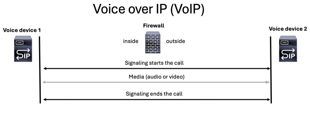
The VoIP is composed of two parts:
- Signaling
- Media (Voice or Video)
VoIP communications always begin with a signaling portion to start a call, then the media (voice or video) is streamed, and finally signaling ends the call.

Note: SIP is the most widely used protocol, so it is consistently represented as the SIP voice server icon in many of the diagrams.

Tip: When troubleshooting a voice issue for ASA or FTD, it is crucial to consider the scenario from the perspective of the user. You need to determine whether the call is established or if there is no audio or one-way audio. This information provides valuable clues about whether the issue lies with the signaling protocol or the media (voice or video) protocol.
Tip: A voice device can manage either voice Real-time Transport Protocol (RTP) traffic, signaling traffic, or both simultaneously. When troubleshooting voice issues, it is essential to remember these main concepts:
++Signaling Servers: These servers are responsible for handling only signaling traffic.
++Media Servers: These servers handle voice RTP traffic exclusively.
++Some devices can handle both tasks.
Signaling
The signaling protocol is the part of a call that starts the voice communication, but not only that, it also performs these functions:
- Keeps communication up.
- Modifies the communication.
- Ends the communication.
Different types of signaling protocols help a call to be established, and the most common include:
- Session Initiation Protocol (SIP)
- H.323
- Media Gateway Control Protocol (MGCP)
- Skinny Call Control Protocol (SCCP)
Tip: It is essential to identify the signaling protocol in use to determine the appropriate ports for packet capture on ASA or FTD. Additionally, having a call flow and network topology is beneficial for understanding the signaling path.
Note: Signaling packets include source and destination IP addresses, aiding in the identification of the parties involved in sending and receiving the RTP media stream.
Media
After the signaling is completed and the signaling components (devices or servers) agree on the media type, the Real Time Protocol (RTP) comes into play to start sending media (audio and/or video) to all parties involved.
RTP is an internet protocol used for streaming media that is sent only after the call is established and it runs over User Datagram Protocol (UDP).
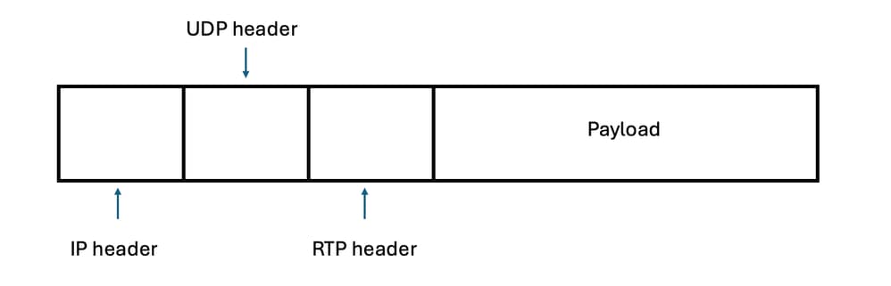
Note: Media can be either voice and/or video and travels on RTP packets.
Signaling components (devices or servers) determine which ports are used for sending or receiving media(audio and/or video). The most common port range for RTP is typically between 16384 and 32767 for most devices.
Note: Certain Cisco devices, such as the ASR and ISR G3 platforms like ISR4K platform, utilize a standardized RTP port range of 8000 to 48200. It is crucial to verify the specific RTP port range configured on your devices, as it can differ from these standardized values and can vary across third-party devices.
Tip: Sometimes the RTP path differs from the signaling path, making it crucial to identify the devices responsible for sending and receiving voice RTP packets. This ensures that you capture UDP traffic between the devices traversing the ASA or FTD.
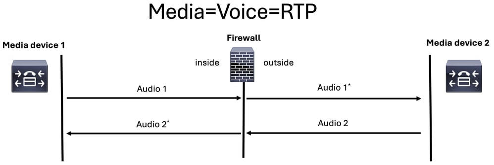
There are two media streams or RTP streams that are generated on a normal voice call:
- one media stream from caller to callee
- one media stream from callee to caller
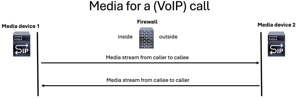
Note: For illustration purposes, the SIP server icon is used to represent either a signaling server or a media server in all the images.
When discussing media streaming in a voice call, it is important to highlight two key scenarios:
- Media Flow-Through
- Media Flow-Around
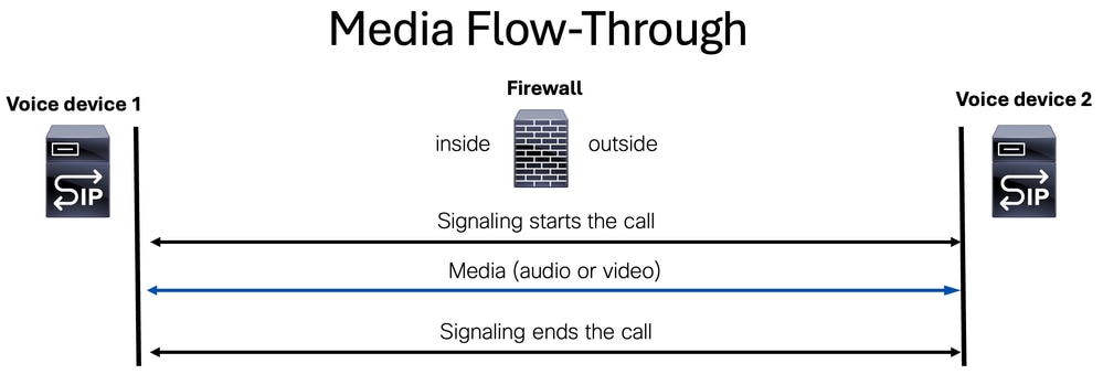
Media Flow-Through
Media flow-through is a mode where both media (voice and/or video) and signaling packets are processed by the same device.
Media Flow-Around
Media stream flow-around is a mode where signaling packets are handled by two separate signaling components(devices or servers), while the media stream (voice or video) is managed by a third device known as the media device.
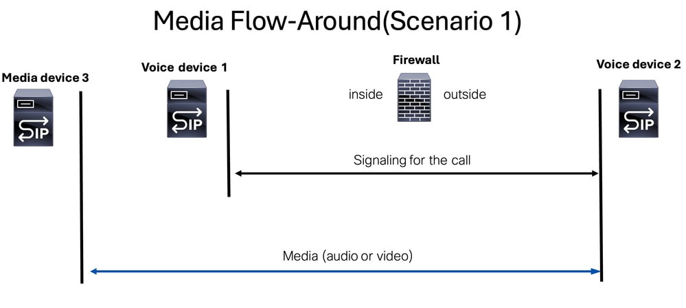
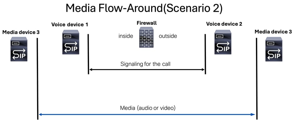
This mode clarifies the roles of the devices involved and the distinction between signaling and media streams or devices.
Note: This is especially important to mention when troubleshooting the access list created could allow the signaling components(devices or servers), but if the media stream is using another media device, we need to allow it as well on the access list of our FW device.
Session Initiation Protocol (SIP)
SIP is an application-layer control protocol defined by the Internet Engineering Task Force (IETF) in RFC 3261.
SIP is a text-based protocol. This means that SIP messages are composed of human-readable text, similar to how HTTP operates.
SIP is designed to address the functions of signaling and session management within a packet telephony network.
SIP can:
- create a call
- modify a call
- terminate a call
SIP can be used either UDP or TCP on standardized port 5060. And if the SIP is encrypted using Transport Layer Security (TLS) it can use the standardized port 5061.
Note: When SIP signaling is encrypted, the actual SIP packets are not visible in packet captures on ASA or FTD devices. However, you are still able to observe the TCP handshake followed by the TLS handshake between the SIP clients and SIP server devices.
Note: SIP inspection is enabled by default on Cisco Secure Firewall Threat Defense (FTD) and Secure Firewall Adaptive Security Appliance (ASA).

Caution: Always corroborate what ports are used for signaling. Remember that the SIP protocol commonly uses ports 5060 or 5061, but some deployments can deviate from these standards and utilize different ports for SIP protocol.
There are three scenarios that can be found when troubleshooting a SIP signaling issue:
- SIP call signaling messages
- SIP OPTION messages
- SIP REGISTER messages
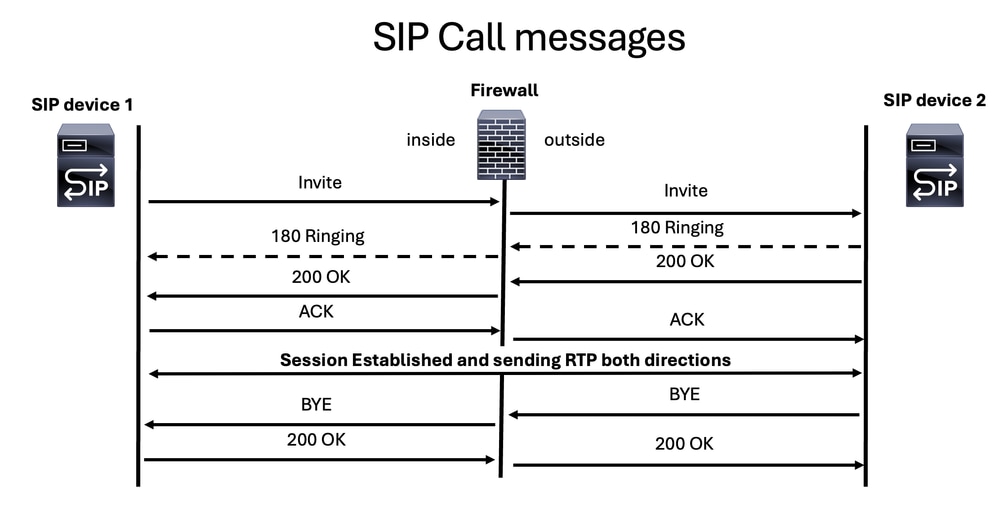
SIP Call Messages
The main SIP messages for establishing and ending a voice call are these:
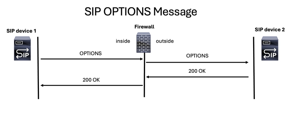
SIP OPTION Messages
SIP OPTIONS messages are important for determining if a SIP device is online and able to respond. It is like ping ICMP message but on SIP world.
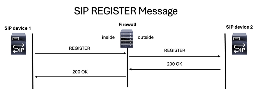
SIP REGISTER Message
Another SIP message you can find during a firewall troubleshooting session is the SIP REGISTER message, which enables a device to register with an SIP server.
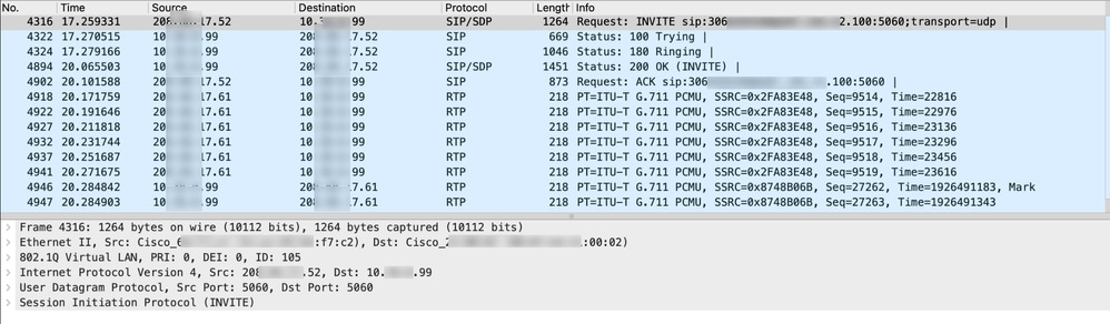
This packet capture shows requests and responses from two SIP devices and also the media (voice) traffic:
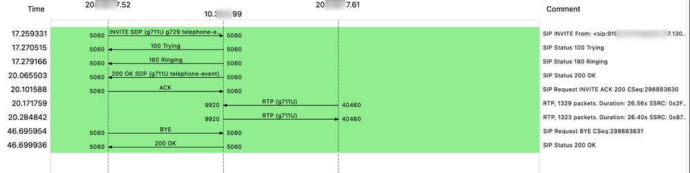
This is an example of a flow of both SIP signaling and RTP media (voice):
Session Description Protocol (SDP)
Session Description Protocol (SDP) is a standard representation used to describe media streams for multimedia sessions. It does not carry media itself but is used to negotiate the media type and format between endpoints. SDP is used in conjunction with Session Initiation Protocol (SIP) to manage and negotiate media characteristics for a session.
Note: MGCP incorporates the concept of SDP, which is utilized for the same purpose.
This is an example of SDP message inside a SIP protocol:
INVITE sip:2003@192.168.245.9:5060 SIP/2.0
Via: SIP/2.0/UDP 192.168.245.6:5060;branch=z9hGXXX5763
Remote-Party-ID: <sip:1001@192.168.245.6>;party=calling;screen=no;privacy=off
From: <sip:1001@192.168.245.6>;tag=4E3XXXC-A9F
To: <sip:2003@192.168.245.9>
Date: Thu, 17 Aug 2025 13:48:52 GMT
Call-ID: 2A7BE22B-XXXXXXXXX-XXXXXXXXX-F940DC75@192.168.245.6
Supported: 100rel,timer,resource-priority,replaces,sdp-anat
Min-SE:  1800
Cisco-Guid: 0350227076-XXXXXXXXX-XXXXXXXXX-1670485135
User-Agent: Cisco-SIPGateway/IOS-15.5.3.S4b
Allow: INVITE, OPTIONS, BYE, CANCEL, ACK, PRACK, UPDATE, REFER, SUBSCRIBE, NOTIFY, INFO, REGISTER
CSeq: 101 INVITE
Timestamp: 150299CC32
Contact: <sip:1001@192.168.245.6:5060>
Expires: 180
Allow-Events: telephone-event
Max-Forwards: 69
Content-Type: application/sdp    <=======Session Description Protocol message start
Content-Disposition: session;handling=required
Content-Length: 266

v=0
o=CiscoSystemsSIP-GW-UserAgent 7317 4642 IN IP4 192.168.245.6
s=SIP Call
c=IN IP4 192.168.245.6
t=0 0
m=audio 8266 RTP/AVP 18 127
c=IN IP4 192.168.245.6
a=rtpmap:18 G729/8000
a=fmtp:18 annexb=no
a=rtpmap:127 telephone-event/8000
a=fmtp:127 0-16
a=ptime:20Note: Some of the SDP messages contain these parameters in the example:
++c-IN IP4: IP Address of the media server
++m=audio: This indicates that the media type is audio.
++8266: This is the port number on which the audio stream is be sent.
++RTP/AVP: This specifies the transport protocol, which is RTP using the Audio/Video Profile (AVP).
++18 127: These are the payload types for the audio codecs. Payload type 18 typically corresponds to the G.729 codec, and 127 is a dynamic payload type that can be assigned to a codec as per the negotiation between the endpoints.
Session Description Protocol (SDP) can be found inside several SIP messages like: INVITE, 183 Session in Progress, 200 OK, ACK, and so on. SDP serves as an answer method to exchange voice and/or video capabilities between parties. When troubleshooting call issues, it is essential to understand three main concepts:
- Early Offer
- Delay Offer
- Early Media
Note: It is crucial to understand the destination of SDP messages, as the inspection feature on the firewall can modify IP addresses not only within SIP headers but also in the SDP section.
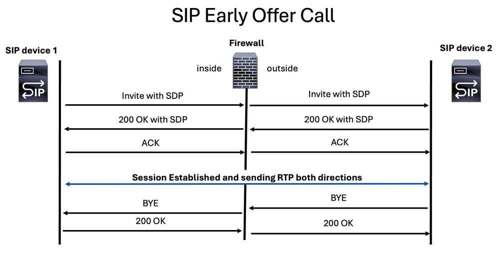
Early Offer
Here media parameters on SDP are found inside the INVITE and 200 OK SIP messages.
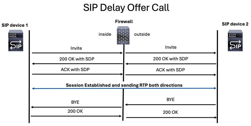
Delay Offer
On this method, the SDP is found on 200 OK and ACK SIP messages.
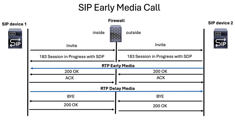
Early Media
Early media is transmitted through a specific SIP message known as the 183 Session Progress response. This message includes the Session Description Protocol (SDP) containing media parameters for the called party. It is commonly used by carriers and SIP providers to send automated voice messages or other media to the caller before the call is officially connected.
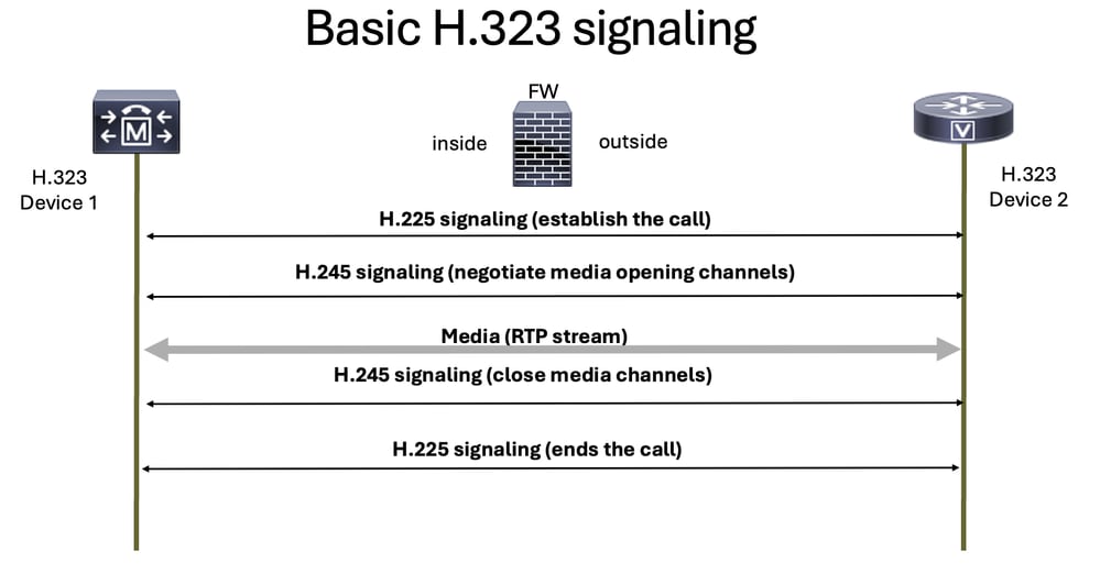
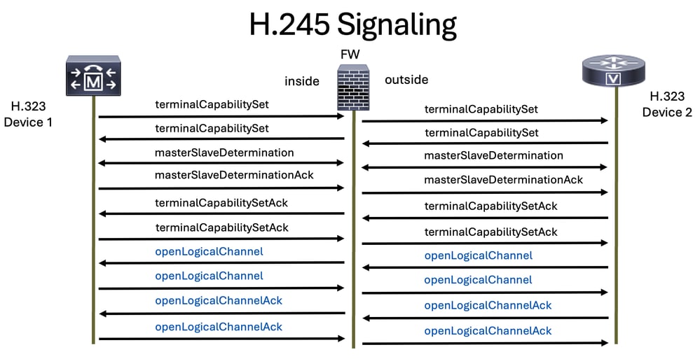
H.323
H.323 is a set of protocols defined by the International Telecommunication Union (ITU) for voice, video, and data communications over packet-switched networks, such as the Internet.
The H.323 protocol is composed of two main components:
- H.225: This handles call signaling, including the setup and termination of calls.
- H.245: This is responsible for capability exchange and the opening and closing of channels for audio and video.
The ports that are used by H.323 signaling protocol are 1718, 1719, and 1720.
Tip: Secure H.323 protocol communications can encounter issues when switching from UDP to TCP due to the use of TLS for encryption, which can cause a firewall to mistakenly block the connection as suspicious activity, so it is crucial to configure the firewall to allow both UDP and TCP traffic for H.323 endpoints or servers.
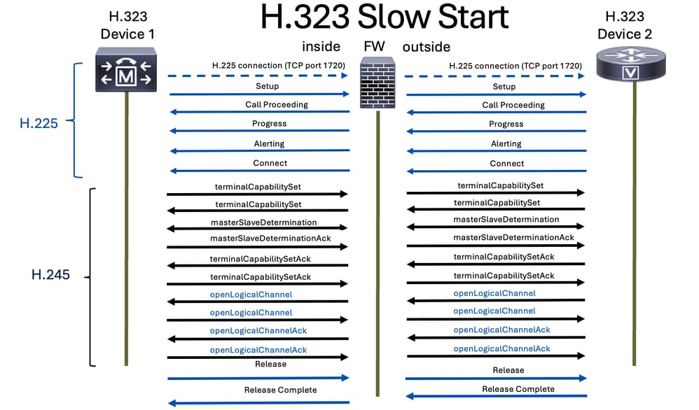
H.323 is a protocol that has two modes of operation: slow start and fast start.
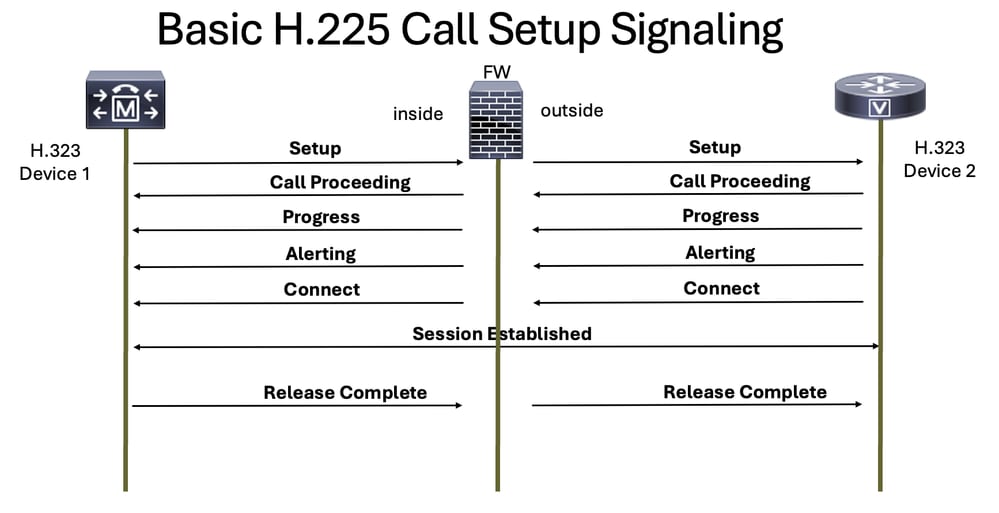
H.225
This protocol is responsible for setting up the call and ending a voice call when one of the parties hangs up.
H.245
H.245 provides these functionalities:
- Terminal Capability Exchange
- Master/Slave Determinations
- Logical Channel Signaling
Note: The terms Master and Slave used in this document are hardcoded into the original H.323 protocol and do not reflect the policies or values of our company. We are committed to promoting inclusive and respectful language.
The H.245 protocol is sent after receiving the H.225 connect message.
This protocol assists in determining which voice protocol is used for RTP, and it is specified on the opening logical channel and closing logical channel messages for it.
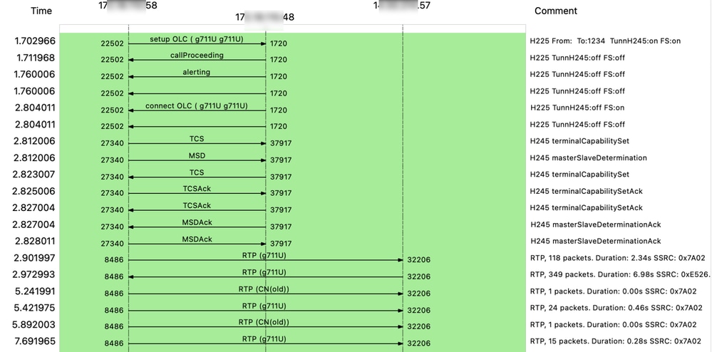
This packet capture shows requests and responses from two H.323 devices with H.225 and H.245 and also the media(voice) traffic:
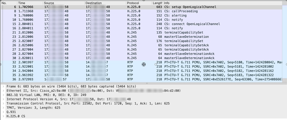
This is an example of a flow of both H.323 signaling with H.225 and H.245 and RTP media (voice):
Note: H.323 inspection is enabled by default on Cisco Secure Firewall Threat Defense (FTD) and Secure Firewall Adaptive Security Appliance (ASA).
Slow Start
In the slow start mode, the call setup process involves several signaling steps before media channels are established. The steps include Setup, Call Proceeding, Alerting, and Connect. After these steps, the H.245 media negotiation is performed separately. This means that the media channels are not established until after the initial call signaling is complete, which can result in a longer setup time.
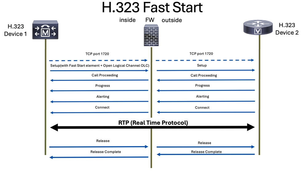
Fast Start
In contrast, the fast start mode allows for the media negotiation to occur within the initial Setup message. This means that the media channels can be established more quickly, as the negotiation is done as part of the initial call setup. Fast start streamlines the process by reducing the number of messages exchanged and the amount of processing required before the media channels are established.
SCCP
Skinny Client Control Protocol (SCCP), often referred to simply as Skinny, is a Cisco proprietary signaling protocol. It is used primarily by Cisco Unified Communications Manager (CUCM), Cisco Unified Communications Manager Express (CME) routers, and Cisco IP Phones to facilitate call setup and control.
The SCCP protocol uses TCP on port 2000 for non secure SCCP and it uses port 2443 for secure SCCP.
These are the common SCCP messages you can find on a SCCP call:
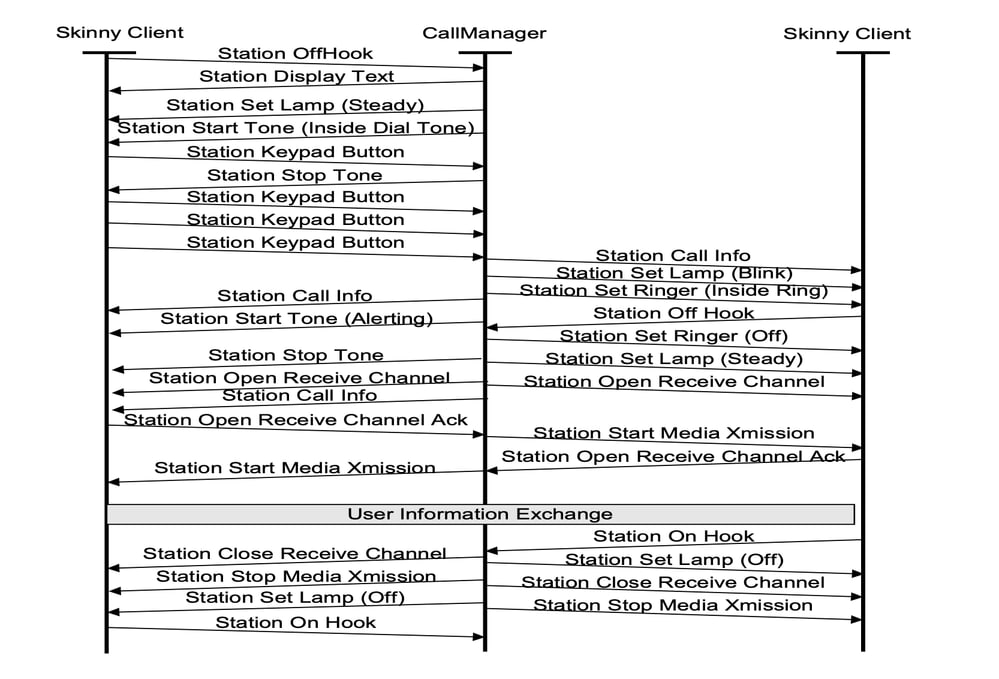
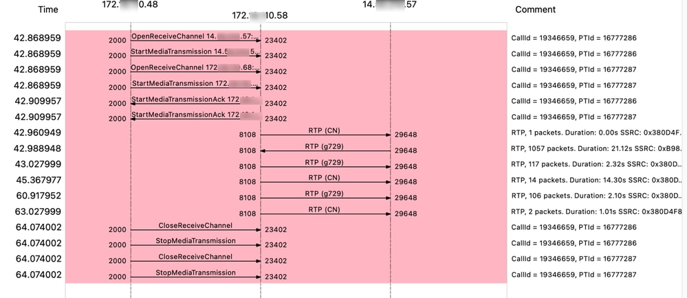
This packet capture shows requests and responses from two SCCP devices and also the media (voice) traffic:
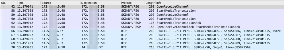
This is an example of a flow of both SCCP signaling and RTP media (voice):
Note: SCCP inspection is enabled by default on Cisco Secure Firewall Threat Defense (FTD) and Secure Firewall Adaptive Security Appliance (ASA).
MGCP
Media Gateway Control Protocol (MGCP) is a protocol used for the control of VoIP calls by a call control device, for example CUCM.
MGCP signaling protocol is defined on RFC 2705 and uses TCP port 2428 and UDP port 2427 for communication.
The MGCP normal packets you expect for a call communication are:
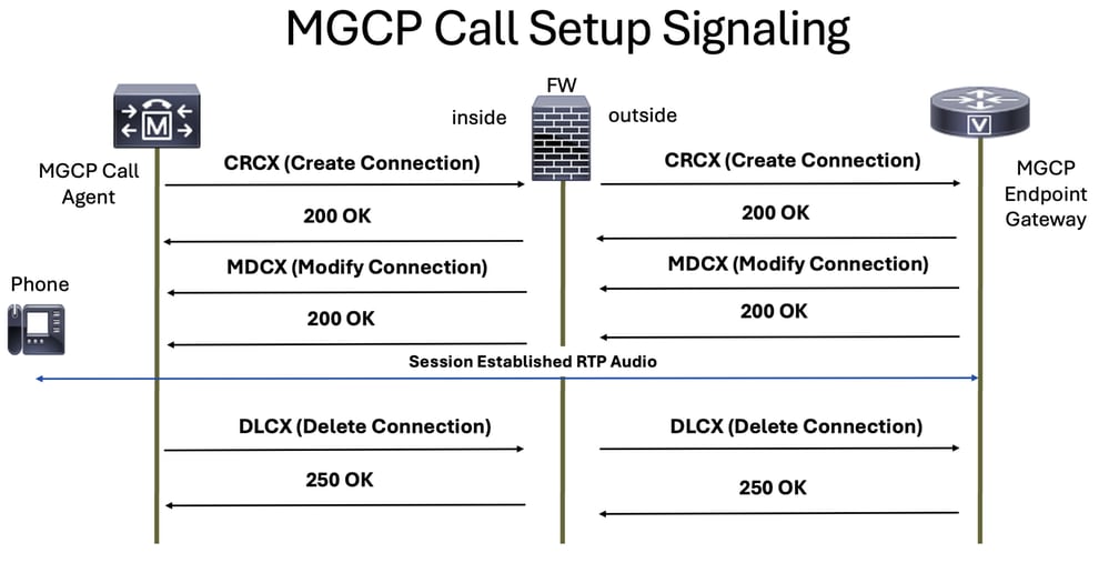
Note: MGCP inspection is not enabled in the default inspection policy on Cisco Secure Firewall Threat Defense (FTD) and Secure Firewall Adaptive Security Appliance (ASA), so you must enable it if you need this inspection.
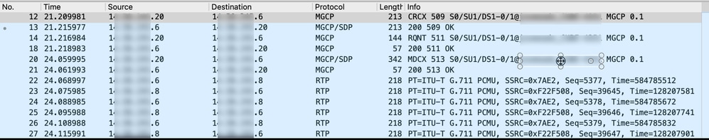
This packet capture shows requests and responses from two MGCP devices and also the media (voice) traffic:
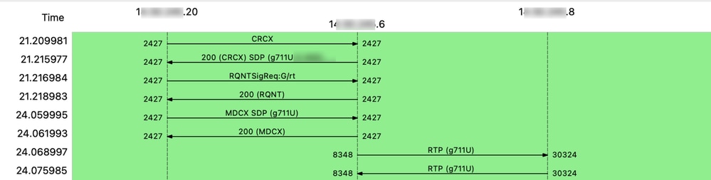
This is an example of a flow of both MGCP signaling and RTP media (voice):
Best Practices
For ASA:
- Use a permit rule that allows the traffic to and from the two signaling components (devices or servers). This can be limited by the ports used on specified signaling VoIP protocol.
- Allow the RTP port range between the media devices that can send and/or receive audio and/or video streams.
Note: Remember that these audio or media devices could be different from the signaling components(devices or servers).
For FTD:
- Define prefilter rules for signaling components (devices or servers) and define the specific port to limit only traffic for specified signaling protocol.
- Configure prefilter for audio and/or video RTP protocol.
Troubleshoot
When troubleshooting voice issues, you need to know if the issue is signaling or media (voice or video) or both, here are some examples that can guide you to differentiate this:
Example of signaling issues:
++The user reports that the call is not established.
++The user is not able to call other users or numbers.
++The SIP Trunk is not coming up, because OPTIONS sip message is not getting response.
++My device is not able to register.
Example of media (voice or video) issues:
++There is a one-way audio issue.
++There is no audio on call.
++There is no video at all.
++The call gets silent.
Tip: During a video call, the SDP can negotiate up to three media lines (m-lines): audio, video, and image. Each m-line corresponds to a separate Real-Time Transport Protocol (RTP) stream per call leg, meaning that there can be up to three distinct RTP streams—one for each media type—on each leg of the call.
Troubleshooting Signaling Issues on Firewall
For troubleshooting the signaling part you need to ensure to:
++Identify all the signaling components (devices or servers) involved in the call from both the ingress and the egress interface and configure appropriate matching criteria on the packet captures on CLI of either Secure FW.
++Remember that the number of signaling messages at the ingress interface must match the egress interface.
++Packet capture can be made more efficient by specifying whether the signaling protocol uses TCP or UDP and by filtering for the expected port number. Since all signaling protocols operate over IP, applying these filters on the CLI helps restrict the amount of traffic you see in your captures.
++For egress interfaces only, ensure that the NAT IP address assigned to outbound traffic is specified in your packet capture filter. This ensures you are capturing the correct traffic as it appears on the egress interface.
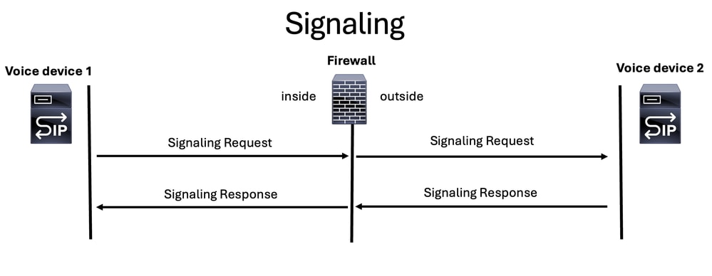
Note: Remember that, regardless of which signaling protocol is used for voice, there must always be a request and a response, and must be consistent on both the ingress and egress interfaces.
Note: Whenever possible, ensure that only one firewall is involved in the communication path. In some deployments, voice signaling and media streams can traverse separate firewalls. In these cases, make sure to include all relevant firewalls in your troubleshooting process
Troubleshooting Media Issues on Firewall
From FW perspective, there are going to be 4 streams that must be analyzed when troubleshooting one-way audio, two-way audio issues or no audio:
-
RTP Stream from Caller to Callee (Ingress Interface).
-
RTP Stream from Caller to Callee (Egress Interface).
-
RTP Stream from Callee to Caller (Egress Interface).
-
RTP Stream from Callee to Caller (Ingress Interface).
Note: Ensure you perform troubleshooting using CLI packet captures on either ASA or LINA mode on the FTD, as this provides greater flexibility to apply multiple matches within a single packet capture.
Troubleshooting SIP Calls
When troubleshooting voice issues on Secure FW (ASA or FTD), you need to carry out these steps:
- Ensure you have the call flow and the topology diagram.
- Ensure that you comprehend the issue from the perspective of the user.
- Understand the path for signaling protocol.
- Understand the path of media RTP protocol.
- Take packet captures on both the ingress and egress interfaces.
- Review the configuration ACL rules and NAT rules.
- Verify that the SIP signaling traffic is not being blocked by the firewall. Additionally, compare the ingress and egress interfaces to analyze voice traffic flow.
- Verify that RTP media traffic is not being blocked by the firewall by comparing the traffic flow on the ingress and egress interfaces.
- Ensure that the signaling devices support inspection, and if not disable that one.
Tip: The SIP signaling messages entering the FW must also be the same as leaving the FW.
Note: The troubleshooting tips for SIP can also be applied to H.323, MGCP, and SCCP protocols.
Related Information
Revision History
| Revision | Publish Date | Comments |
|---|---|---|
1.0 |
06-Aug-2025
|
Initial Release |
Contributed by Cisco Engineers
- Victor Hugo Gil GuzmanTechnical Consulting Engineer
 Feedback
Contact Cisco
- Open a Support Case

- (Requires a Cisco Service Contract)