Edge Compute and AI via Cisco Embedded Networking and Third Party Modules White Paper
Available Languages
Bias-Free Language
The documentation set for this product strives to use bias-free language. For the purposes of this documentation set, bias-free is defined as language that does not imply discrimination based on age, disability, gender, racial identity, ethnic identity, sexual orientation, socioeconomic status, and intersectionality. Exceptions may be present in the documentation due to language that is hardcoded in the user interfaces of the product software, language used based on RFP documentation, or language that is used by a referenced third-party product. Learn more about how Cisco is using Inclusive Language.
This white paper addresses 3 main topics to assist hardware engineers and technical decision makers create more complex integrated solutions using Cisco Embedded Networking Products:
● Introduce the concept of combining a Cisco® Embedded Series Router (ESR) and Embedded Services Switch (ESS) in a single enclosure.
● Describe the unique ability of Cisco embedded products to deliver whatever edge compute a customer may need, with a very broad continuum of integration options using third-party modules.
● Introduce the idea of edge AI.
There are many reasons for edge compute, as well as many types of operations being done on the data. Generally, preprocessing data close to the source to reduce latency and gain efficiencies regarding backhaul bandwidth is a very common goal, but other requirements may exist.
For example, a military application might need to encrypt a data stream using an encryption method that is government controlled and requires classified access to the devices in question.
Or we might be building a machine-based optical recognition system in which the application is trying to distinguish between different types of ground or air vehicles and will report back only what it detected rather than sending a continuous video stream. Or it may be a simple license plate reader that captures plate numbers with a time stamp.
As we can see from the above examples, different compute devices will be required for each application— and within each category they may need to scale up or down. Just reading a license plate requires less compute capacity than being able to also log whether the tag was on a black car vs. a blue bus vs. a red semi truck. The devices we use for the encryption example may be very different from those needed for the machine vision use case.
Regarding the actual compute hardware, we need to consider hardware cost, performance, power, heat, physical module size, operating environment, availability, and product longevity, to name a few.
In addition, we need to know what programming techniques and languages will be used, and what the solution for application orchestration will be.
An application could simply operate in Linux user space, or it could use a variety of virtualization techniques, such as KVM, Docker containers, Podman containers, Snaps, etc. Kubernetes and Red Hat OpenShift are popular choices for application management and orchestration, but many more exist.
All of these are important considerations for delivering an optimal edge compute solution for the customer.
How to create a permanent Ethernet link between the Cisco embedded module and embedded compute
Let’s begin by using a concept from one of the design notes we give to our partners to provide some suggestions regarding what may be possible with solutions they can create using Cisco embedded routers and switches. This concept is typically used when we need to provide more switch ports than the four 1 Gigabit Ethernet (1GE) ports native to the Cisco ESR6300 Embedded Series Router for the customer’s application. The figure below shows a combined solution in which a partner can consider a system with a permanently coupled ESR6300 and Cisco Embedded Services 3300 Series Switch (ESS3300) in one enclosure.
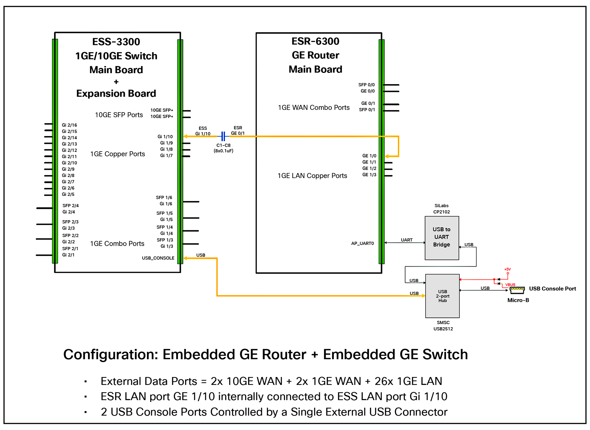
ESR6300 and ESS3300 deployed in one enclosure
Let’s zoom in on the actual connection.
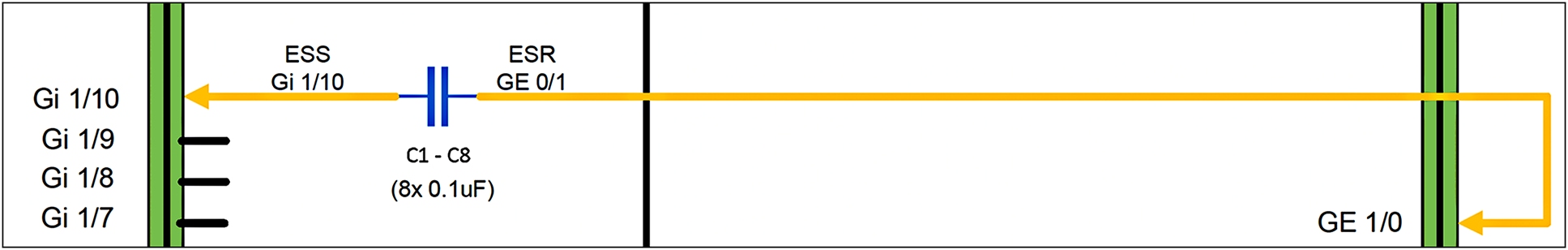
A closer look at the ESR and ESS connection
What we see is that you can create a combined ESR and ESS solution with the help of eight small surface-mount capacitors. Several Cisco Embedded Partners have already delivered this type of solution. Sometimes, however, we have more to consider when we have a solution that combines products from multiple vendors.
In embedded applications, many times one can have Ethernet connections between different network elements without a pluggable cable of any kind, that is, neither Unshielded Twisted Pair (UTP) nor fiber optic, as we have seen in Figures 1 and 2. This type of connection may be a few traces on a circuit board with some passive elements such as capacitors or signal transformers.
For Ethernet connections between external devices, our lives are simplified by the fact that IEEE standards exist. If we consider the types of ports and devices at both ends, the types of cables being used, and the distance in question, and then we abide by the requirements for that interface, the physical connection will very likely be established. For example, if we have a network LAN switch and PC that are connected using 100 feet of 1000BASE-T on Category 6 UTP cable, we have little doubt that a physical connection can be easily established, assuming that all the equipment is working.
For creating a board-to-board permanent Ethernet connection, there are also a few design considerations. Generally, these are 100-ohm differential traces and there are two basic types of PHY drivers, current mode and voltage mode. Since these connections are within the same enclosure on the same carrier board, most of the protection circuitry can be eliminated, since there are none of the typical hazards encountered with wiring within a building infrastructure. We still need to make the Ethernet PHY Integrated Circuits (ICs) think they are being used with the typical magnetics and protection circuits. To do this we need an understanding of the driver circuits used by the IC vendor. For 1000BASE-T, also known as Gigabit Ethernet (GE), this comes down to two options, a current mode driver or a voltage mode driver. A voltage mode driver for both devices is usually the easier option to work with. Voltage mode PHY to voltage mode PHY may use capacitive coupling to save board space and cost, but it is wise to consult the IC vendors of both devices to be sure. Voltage mode to current mode or current mode to current mode will generally need to use transformer coupling.
To summarize, we can use permanent Ethernet connections on a carrier board to link different functional modules to create unique integrated solutions once we have identified the driver types and employ the proper “glue” circuitry.
Now we will look at the broad possibilities of integrating Cisco embedded networking (ESR and/or ESS) with embedded compute and embedded AI.
Types of Small Form-Factor compute modules and scalability options
For comparison, a typical credit card, ISO ID-1 format, is 3.37 inches (85.72 mm) wide by 2.12 inches (53.97 mm) high.
Raspberry Pi Compute Module series: Low cost
The Raspberry Pi Compute Module 4 (CM4) has been transformed into both industrial and defense compute devices by many companies throughout the world. There were earlier CM2 and CM3 designs, but new designs should focus on the CM4 and CM5. Such a design very likely offers the lowest-cost option for a low cost of goods, a huge installed customer base, and a huge developer ecosystem.
The following is the CM4 description provided by the manufacturer:
“The power of Raspberry Pi 4 in a compact form factor for deeply embedded applications. Raspberry Pi Compute Module 4 incorporates a quad-core ARM Cortex-A72 processor, dual video output, and a wide selection of other interfaces. Available in 32 variants, with a range of RAM and eMMC Flash options, and with or without wireless connectivity.”
Compute Module 4 will remain in production until at least January 2034.
Source: https://www.raspberrypi.com/products/compute-module-4/?variant=raspberry-pi-cm4001000
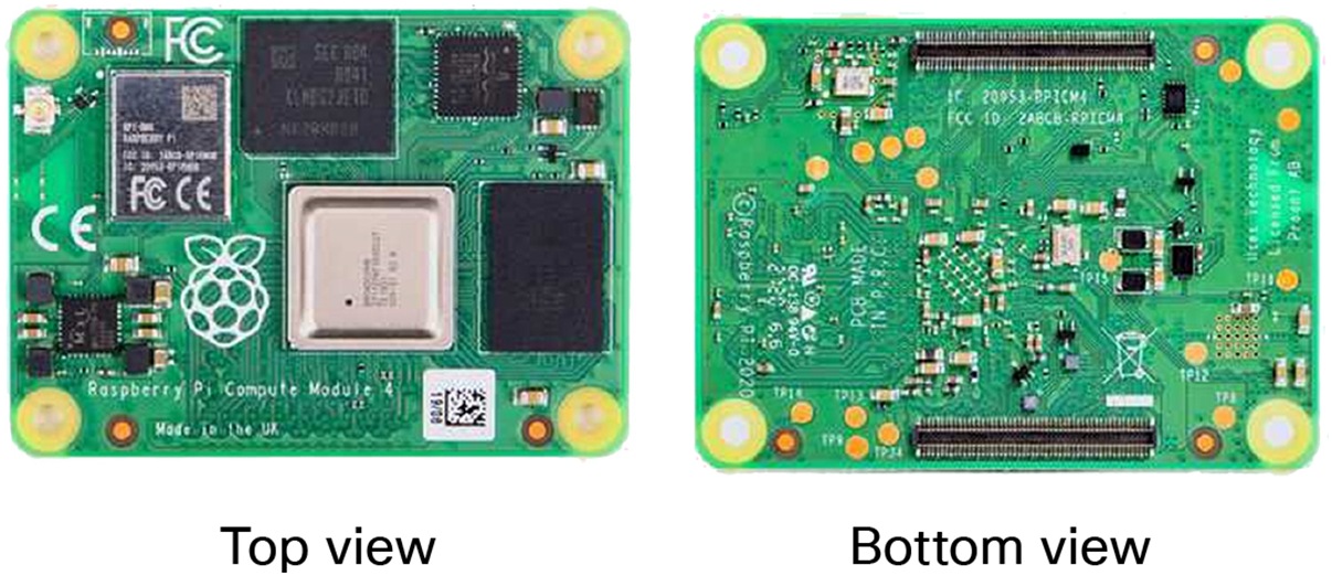
Raspberry Pi CM4
The size of a CM4 is 2.16 inches by 1.57 inches (55 mm by 40 mm), so it is less than half the size of a typical credit card. It uses a voltage mode PHY, which may make it possible to use capacitive coupling for an onboard Ethernet connection, but, as mentioned earlier, consult the IC vendors regarding feasibility.
COM Express: Many different options at a higher cost
What is COM Express?
Let’s answer this using the words of the nonprofit consortium that defines it, PICMG (PCI Industrial Computer Manufacturers Group), which has over 140 member companies.
“COM Express is a family of modular, small form factor Computer-On-Module (COM) specifications for mid-range edge processing and networking that has become one of the most popular embedded hardware standards in the world. Since its initial ratification in 2005, COM Express has spawned eight different Types, four different sizes, and three major revisions while retaining a modular architecture that promotes vendor interoperability and technology reuse.”
“COM Express defines four module sizes (mini, Compact, Basic, and Extended) to accommodate a wide range of performance and space requirements across applications like industrial automation, robotics, medical, retail, digital signage, and gaming. Ruggedized and high-temperature products are also available for demanding applications including mil/aero, transportation, and remote data acquisition.”

COM Express module sizes
Source: https://www.picmg.org/openstandards/com-express/#module-sizes
COM Express modules typically use the x86 CPU architecture, but others do exist. These solutions can scale to far more compute power and resource options but also have a much higher cost than the Raspberry Pi compute modules. COM Express Mini is about the size of a typical credit card.
A COM Express vendor directory can be found at https://www.picmg.org/openstandards/com-express/ Scroll down to “COM Express Products from Our Members” and you will find many products to choose from.
Since there is a wide variety of manufacturers and offerings, the designer must take care to evaluate board-to-board compatibility with the Cisco embedded product being considered as regards board-to-board Ethernet.
NVIDIA Jetson: AI applications
According to the NVIDIA Developer website,
“NVIDIA Jetson brings accelerated AI performance to the Edge in a power-efficient and compact form factor. Together with NVIDIA JetPack SDK, these Jetson modules open the door for you to develop and deploy innovative products across all industries.”
Source: https://developer.nvidia.com/embedded/jetson-modules
The low end of this series begins with the NVIDIA Jetson Nano at 472 gigaflops using a 128-core NVIDIA Maxwell architecture GPU, and it currently tops out with the Jetson AGX Orin 64 GB at 275 teraflops using a 2048-core NVIDIA Ampere architecture GPU with 64 tensor cores.
Figure 5 shows an NVIDIA Jetson Nano, which measures 2.74 by 1.77 inches (69.6 by 45 mm), making it slightly smaller than a typical credit card. It has a single onboard 1GE network port.
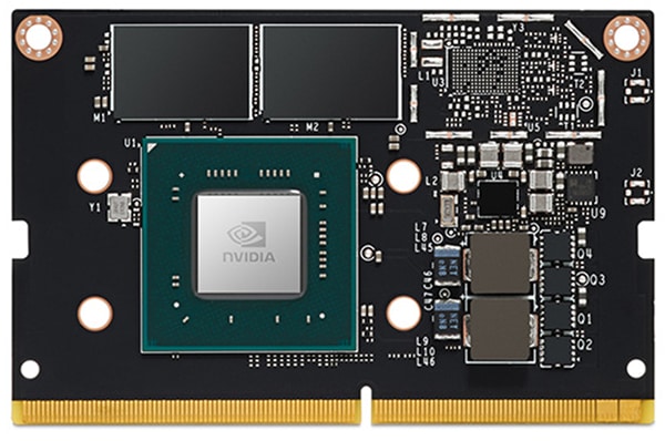
NVIDIA Jetson Nano
For more information, explore the Jetson Community Resources pages at https://developer.nvidia.com/embedded/community/resources
NVIDIA has a FAQ for the Jetson product line at https://developer.nvidia.com/embedded/faq
You can also contact NVIDIA directly for more details.
Cisco Embedded Series Router and Embedded Services Switching products
Cisco ESR6300
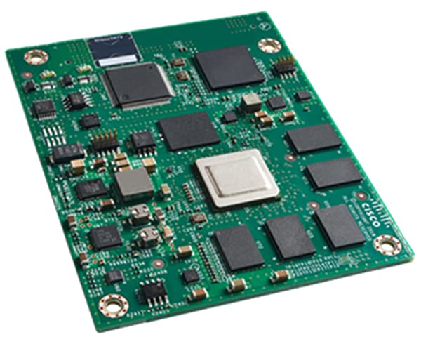
Cisco ESR6300
The Cisco ESR6300 Embedded Series Router is a high-performance, ruggedized router designed for use in harsh environments, offering reliable operation in extreme temperatures and under shock and vibration conditions typical for mobile applications in rugged terrain. With onboard hardware encryption, the Cisco ESR6300 offloads encryption processing from the routing engine to provide highly secure yet scalable video, voice, and data services for mobile and embedded outdoor networks. The router offers high performance, six 1GE interfaces (two routed and four switched), and a rich Cisco IOS® XE Software feature set, providing investment protection for customers deploying bandwidth-intensive applications in mobile or embedded networks in heavy industrial, public safety, transportation, defense, and energy markets.
The ESR6300 is an embedded router module with a compact form factor of 3.0 by 3.77 inches (76.2 by 95.88 mm). The compact design simplifies integration and enables the module to be used in a wide variety of embedded applications.
For more details, see the ESR6300 Series data sheet at
https://www.cisco.com/c/en/us/products/collateral/routers/datasheet-c78-742901.html
4x 1GE ESR6300 LAN ports – voltage mode PHY (supports capacitive coupling if the peer does)
2x 1GE ESR6300 WAN ports – current mode PHY (requires transformer coupling)
Cisco ESS3300
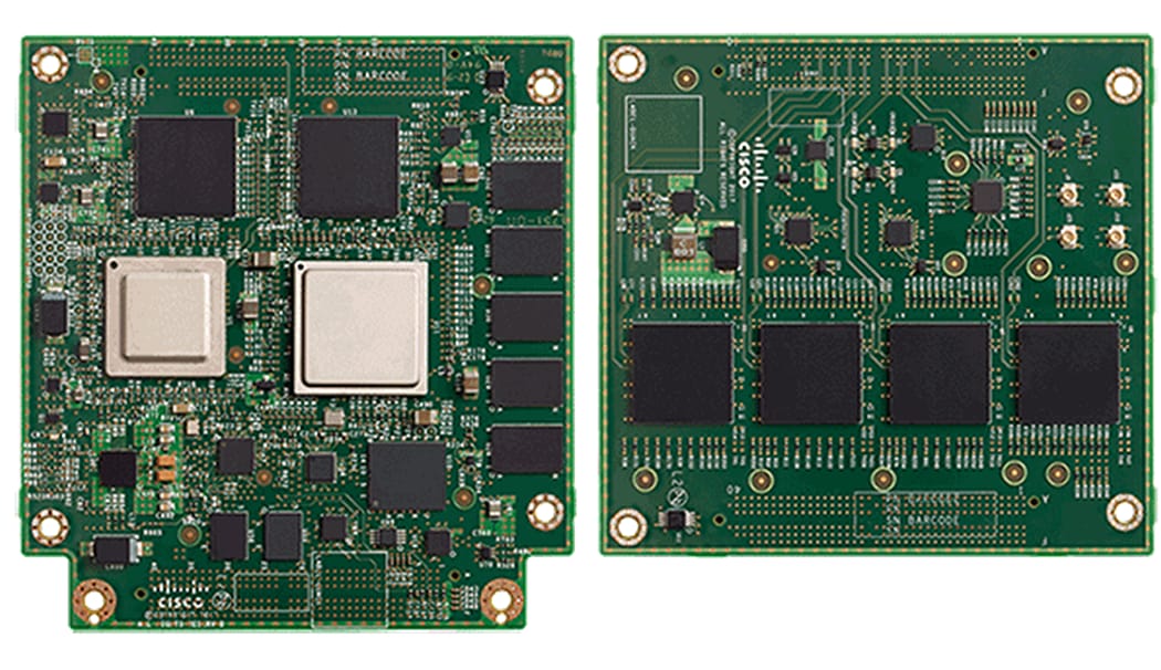
Cisco ESS3300
The Cisco Embedded Services 3300 Series Switches (ESS3300) revolutionize Cisco’s embedded networking portfolio with 1GE/10GE capabilities. ESS3300 switches are optimized to meet the specialized form-factor, ruggedization, port density, and power needs of many applications requiring customization and complement Cisco’s off-the-shelf Industrial Ethernet switching portfolio.
The Small Form Factor board configuration options and optimized power consumption provide Cisco partners and integrators the flexibility to design custom solutions for defense, oil and gas, transportation, mining, and other industries. The ESS3300 runs the trusted and feature-rich Cisco IOS XE Software, allowing Cisco partners and integrators to offer their customers the familiar Cisco IOS command-line interface and management experience on their ESS3300–based solutions. The ESS3300 consists of a main board that delivers two 10GE uplink ports and eight 1GE downlink ports. The ESS3300 has an optional expansion module that adds sixteen 1GE downlink ports. Both boards measure approximately 4 by 4 inches.
For more details, see the ESS3300 Series data sheet at https://www.cisco.com/c/en/us/products/collateral/switches/embedded-service-3000-series-switches/embedded-services-3300-series-ds.html
24x 1GE ESS3300 downlink ports – voltage mode PHY (supports capacitive coupling if the peer does)
2x 10GE uplink ports – these are SFP+ and require I2C and GPIO control signals for approved Cisco SFPs, and hence are not available for board-to-board linking
ESS9300
Use of the Cisco Catalyst™ ESS9300 Embedded Series Switch is currently not possible. All ports are SFP+ and require I2C and GPIO control signals for approved Cisco SFPs.
In conclusion, what we have covered here should give designers some suggestions that can enable them to develop solutions that extend the possibilities for Cisco embedded networking beyond single-module solutions to a richer set of integrated solutions scaling both network connectivity and edge compute or edge AI.
Learn more about Cisco embedded networking solutions.