MSE - Context Aware Mobility Solution Deployment Guide
Available Languages
Contents
Introduction
The purpose of this document is to provide configuration and deployment guidelines, as well as troubleshooting tips and answers to frequently asked technical questions for those that add the Cisco Mobility Services Engine (MSE) and run Context Aware Services to a Cisco Unified WLAN. The purpose of this document is to:
-
Explain the various elements and framework for the Cisco Mobility Solution
-
Provide general deployment guidelines to deploy Cisco Mobility Solution
This document does not provide configuration details for the MSE and associated components. This information is provided in other documents, and references are provided. Refer to the Related Information section for a list of documents about the configuration and design of Context Aware Mobility Services. Adaptive wIPS configuration is also not covered in this document.
Prerequisites
Requirements
There are no specific requirements for this document.
Components Used
This document is not restricted to specific software and hardware versions.
Conventions
Refer to Cisco Technical Tips Conventions for more information on document conventions.
Background Information
The Cisco MSE provides the ability to track the physical location of Network Devices, both wired and wireless, using wireless LAN controllers (WLCs) and Cisco Aironet Lightweight Access Points (LAPs). This solution allows a customer to track any Wi-Fi device, including clients, active RFID tags, and rogue clients and access points (APs). It was designed with these requirements in mind:
-
Manageability—Cisco Wireless Control System (WCS) is used to administer and monitor the MSE. Moreover, the MSE integrates directly into the wireless LAN architecture, which provides one unified network to manage instead of multiple disparate wireless networks.
-
Scalability—The Cisco MSE series can simultaneously track up to 18,000 network elements. The WCS can manage multiple Mobility Services Engines for greater scalability. The controller, WCS, and MSE are implemented through separate devices to deliver greater scalability and performance.
-
Security—The MSE, WCS, and wireless LAN controller provide robust secure interfaces and secure protocols to access data. The MSE records historical location information that can be used for audit trails and regulatory compliance.
-
Open and standards based—The MSE has a SOAP/XML API that can be accessed by external systems and applications that can leverage location information from the MSE.
-
Easy deployment of business applications—The MSE can be integrated with new business applications such as asset tracking, inventory management, location-based security, or automated workflow management.
This document is divided into five sections:
Section 1: Solution Overview
Context Aware Service (CAS) provides the capability for a Wi-Fi 802.11a/b/g/n network to determine the location of a person or object with an active Wi-Fi device, such as a wireless client or active RFID tag and/or associated data that can be passed by the end point through the wireless infrastructure to an upstream client. When a Cisco Mobility Service Engine (MSE) is added to a Cisco Unified Wireless Network (CUWN) with an appropriately licensed version of WCS, it assumes responsibility for several important tasks:
-
Execution of positioning algorithms
-
Maintenance of calibration information
-
Trigger and dispatch of location notifications
-
Process of statistics and historical location
-
Depository for geographical information, maps, and all wireless devices
WCS is the management system that interfaces with the MSE and serves user interface (UI) for the services that the MSE provides. Although it is possible to access the MSE directly through SSH or a console session for maintenance and diagnostic purposes, all operator and user interaction with the MSE is typically performed through WCS (for management) or a third-party location client application.
Terminology
With the Cisco centralized wireless LAN architecture and Context-Aware Location Services, administrators can determine the location of any 802.11-based device, as well as the specific type or status of each device. Clients (associated, probing, etc.), rogue access points, rogue clients, and active tags can all be identified and located by the system. This information is made available through the API within seconds of an event occurrence and can be retained by the MSE database for historical lookup or security audits.
Mobility Services Engine (MSE): MSE supports a suite of mobility services programs. Designed as an open platform, the MSE supports mobility services software in a modular fashion with various configuration options based on network topology and the types of services required. The value of the MSE is delivered through the various mobility services applications. Cisco supports existent and future software that include these:
-
Context-Aware Services: These programs capture and integrate into business processes detailed contextual information about such things as location, temperature, availability, and applications used. Context-aware applications feature a wide range of location options that include real-time location, presence detection, chokepoint visibility, and telemetry. Support for enhanced received signal strength indication (RSSI) and time difference of arrival (TDoA) technology delivers greater scale accuracy and performance for a broad range of environments. Context Aware software consists of two major components:
-
Context Aware Engine for Clients: The Cisco location engine (RSSI) is used to track Wi-Fi clients, rogue clients, rogue APs, and wired clients.
-
Context Aware Engine for Tags: The partner (AeroScout) location engine (both RSSI and TDOA) is used to track Wi-Fi active RFID tag.
Third-party applications are supported through the MSE API.
-
-
Adaptive Wireless Intrusion Prevention System (wIPS): wIPS software provides visibility and comprehensive threat prevention for the mobility network through monitoring, alerts, classifying, and remediation of wireless and wired network vulnerabilities.
Network Mobility Services Protocol: Cisco-defined protocol that is used for secure communication between the WLC and MSE.
Wireless Control System (WCS): Wireless network management system developed and supported by Cisco Systems. Includes these capabilities:
-
WLAN configuration
-
WLAN performance monitoring
-
Reporting (real-time and historical)
-
Graphical view of network (wireless LAN controllers, access points, clients and tags)
Wireless LAN Controller (WLC): The CUWN architecture centralizes WLAN configuration and control into a device called a WLAN Controller (WLC). This allows the entire WLAN to operate as an intelligent network that uses wireless as the access medium to support advanced services, unlike legacy 802.11 WLAN infrastructures that are built from autonomous, discrete access points. The CUWN simplifies operational management by collapsing large numbers of managed end-points—autonomous access points—into a single managed system comprised of the WLAN controller(s) and its corresponding, joined access points.
In the CUWN architecture, APs are “lightweight,” which means that they cannot act independently of a WLC. APs are typically “zero-touch” deployed, and no individual configuration of APs is required. The APs learn the IP address of one or more WLC through a controller discovery algorithm and then establish a trust relationship with a controller through a “join” process. Once the trust relationship is established, the WLC pushes firmware to the AP, if necessary, and a run-time configuration. APs do not store a configuration locally.
Clients: All devices associated with controller-based, lightweight access points on a wireless network.
Rogue Access Point: Any access point that is determined not to be part of the wireless LAN mobility group that detected it. This consists of all non-system access points within RF range of a lightweight access points, which includes those on the wired network or those on another wired network (such as an access point of a neighbor). Because all lightweight access points use a hash as part of the beacon frame with a special key, even spoofed infrastructure access points are identified as rogue access points rather than mistaken to be legitimate access points flagged in WCS as spoof access points.
Rogue Clients: All devices that are associated to rogue access points.
Active RFID Tags: Wi-Fi device that can be detected and located on a Wi-Fi network. There is wide variety of Wi-Fi compatible tags available in the market. Tags offer a range of features that include telemetry, such as motion and environmental data such as temperature and humidity, call buttons, indoor and outdoor operation, intrinsically safe versions, and flexible mounting options.
The MSE provides the ability to track up to 18,000 devices (tags, clients, and rogue clients/APs). Figure 1 is an example of a floor map as shown in the WCS, and displays tags, clients, rogue clients and rogue APs. The floor map illustrates the scale and variety of classes of devices that can be tracked by the MSE. WCS provides the capability to define search parameters to display only in a subset of devices. For example, a biomedical user can want to see only infusion pumps and EKG machines named with friendly identifiers rather than rogue devices or devices with cryptic MAC or IP addresses.
Figure 1: WCS Floor Map with Tracked Devices 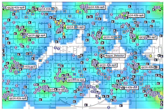
Client: 
Tag: 
Rogue AP (red=malicious, green=friendly, gray=unclassified) 
Rogue Clients: 
Technology Background Information
There are two technologies that are used to track Wi-Fi devices with the Cisco Mobility Solution:
-
RSSI (Received Signal Strength Indication)
-
TDOA (Time Difference of Arrival)
Details on these technologies are provided in the Wi-Fi Location-Based Services 4.1 Design Guide.
RSSI (Received Signal Strength Indication)
RSSI is the measured power of a received radio signal. The packets transmitted by any wireless device are received at multiple APs (provided that those APs listen on the channel on which the frame was transmitted). The APs forward these packets to the wireless LAN controller along with the correspondent RSSI information measured at the AP. The wireless LAN controller aggregates this information on a per device basis from different APs. This data is forwarded to the MSE through NMSP. The Context Aware Services that reside on the MSE use the RSSI data received from one or more WLCs to determine the location of a wireless device.
RSSI is usually preferred for indoor or low ceiling environments, which can result in reflection of the signals. Unlike TDOA, RSSI does not require exact time synchronization amongst APs. With the measured RSSI values from different APs, the probability of the location of a device is calculated at different points on the floor. Based on this probability, the location is returned as the estimated location.
TDOA (Time Difference of Arrival)
When you track tags in outdoor and outdoor-like environments, such as are found in indoor high-ceiling environments, the time difference on arrival (TDOA) mechanism is the preferred method to determine device location. With TDOA, the location of a WLAN device is determined based on the difference in time of arrival (TOA) of the signal that it transmits as seen by three or more time-synchronized Wi-Fi TDOA receivers. The time of arrival data is collected and reported to the Context Aware Engine for Tags that reside on the MSE, which computes the time-differences-of-arrival between multiple pairs of Wi-Fi TDOA receivers. The time required for a given message to be received by different Wi-Fi TDOA receivers is proportional to the length of the transmission path between the mobile transmitting device and each TDOA receiver. This mechanism of calculation device location requires time synchronization between the Wi-Fi TDOA receivers.
In order to compute a position accurately, this method requires a set of at least three Wi-Fi TDOA receivers. The distance between Wi-Fi TDOA receivers is relatively larger than the distance between Access Points that are required for indoor RSSI positioning. As with RSSI positioning, this method relies on unidirectional communication (tag transmitting notification frame, no association required).
Refer to the Context-Aware Service Software Configuration Guide.
Active RFID Tags
CCX-compliant active RFID tags are detected on a Wi-Fi network based on tag notification frames that are sent by the tag and received by an 802.11 AP. The tag notification frame rate can be programmed based on the specific use case scenario. Typically, tags are configured to transmit tag notification frames every 3-5 minutes to optimize frequent location updates and battery life.
The call button feature provides the ability to trigger events based on push button on the tag. This enables advanced functionality, such as emergency reporting or parts replenishment. Some tags provide more than one call button. The second call button can be programmed for additional functionality.
Tags can store pre-programmed messages that can be received by the wireless network infrastructure. A battery is used to power active tags, which provides up to four years of battery life. Battery life is dependent upon a number of tag configuration parameters that includes the frequency of tag notification frame transmission and repetition rate. Tags can report on their battery level and alert when low. Tags can also have a built-in motion sensor to transmit tag notification frames upon movement. This helps to conserve battery life when the tag is stationary; configure the tags to transmit less frequently when they do not move.
There is another category of tags that add advanced sensor technology to accurately monitor the condition of an asset, such as its ambient temperature, in addition to other location and status information. These sensor tags use standard Wi-Fi networks to transport the asset location and sensor data and do not require dedicated or proprietary sensor networks.
Wi-Fi RFID tags that are compliant with the Cisco Compatible Extensions (CCX) for Wi-Fi Tags specification can optionally pass tag telemetry information to the location-aware Cisco UWN as part of their tag message payload. Telemetry information is received by access points and collected by the WLCs. At MSE startup, the MSE subscribes for all the service in which it is interested, such as the measurements for tags. The WLC continues to send the MSE notifications at the end of each aggregation cycle.
Telemetry information is transmitted from a CCX-compatible tag and is received by one or more APs and/or location receivers, that is, Wi-Fi TDOA receivers, which, in turn, pass the telemetry information to their respective registered WLAN controllers. If the tags are configured to send multiple frame copies (or bursts) per channel, the controller eliminates any duplicate tag telemetry and passes the distilled telemetry values to the MSE. The database in the MSE is updated with the new telemetry information and makes it available to location clients through the SOAP/XML API.
In the case of a tag that passes telemetry value, NMSP is designed to efficiently transport telemetry values from multiple tags in a similar fashion. Telemetry traffic from multiple tags is aggregated by the WLC with each NMSP endpoint capable of performing NMSP frame fragmentation and reassembly if required. All tag data can be included in the northbound notifications, which includes telemetry, call buttons, chokepoint encounters, etc.
System Architecture
The MSE integrates with the Cisco centralized wireless LAN architecture as shown in Figure 2. The MSE sits out of the data path of the wireless LAN (see diagram) and receives data from the WLC through NMSP. WCS is used to configure the MSE. Once configured, the MSE is self contained.
Figure 2: System Architecture 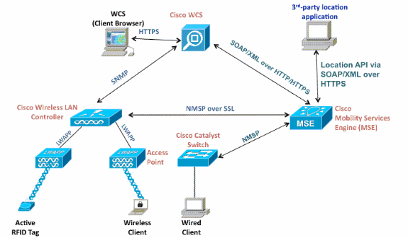
When you deploy the Context Aware solution, consideration must be given to the type of devices tracked and the maximum device count. You can track any of the five device types (Wi-Fi clients, active RFID tags, rogue clients, rogue APs, or wired clients) to be configured individually or for simultaneous tracking.
One MSE can be managed by only one WCS, that is, a single MSE cannot be managed by multiple WCS instances, but a single WCS can manage multiple MSEs. When the number of devices to be managed exceeds the capacity of a single MSE, you need to deploy multiple, independent MSEs. The ability to deploy multiple MSEs for scaling applies to all services currently supported on MSE. The maximum number of devices that can be tracked by one Cisco MSE 3350 is 18,000 devices (combination of Wi-Fi clients, active RFID tags, rogue clients, rogue APs, and wired clients) as part of Context Aware Service. The Cisco MSE 3310 can track up to 2,000 devices. When the number of devices to be managed exceeds the capacity of a single MSE box, multiple, independent MSE appliances need to be deployed. This can require MSEs on specific controllers, especially on large campuses where roaming of clients or assets can cross different physical buildings or domains. In this instance, controllers can communicate with a maximum of 10 MSE appliances.
Cisco LAPs operate in a unique dual mode that detect devices both on the channels where they service clients and also on all other channels if they periodically background scan while still provide data access to their wireless clients. The gathered raw location data is then forwarded from each access point to its associated WLC through the LWAPP or standards-based CAPWAP protocol. Data is transported between the wireless LAN controller and the MSE through a secure NMSP connection.
Cisco WCS is used to manage and configure the MSE, and it can also become the visual front-end of the MSE to display Wi-Fi devices that are tracked. All device (wired and wireless) details and specific historical location information can be accessed with the MSE northbound API. WCS uses this interface to visualize location information, as well as view and configure Context Aware parameters.
The Cisco Mobility Solution consists of two location engines with a single unified application programming interface (API):
-
Context Aware Engine for Clients (Cisco engine)
-
Context Aware Engine for Tags (partner engine)
The Context Aware Engine for Clients is an RSSI-based solution and is ideal to track Wi-Fi client devices in indoor spaces, for example, offices, hospitals, or other low-ceiling environments. This engine ships by default on all Cisco MSE servers. In addition to the Cisco MSE, customers need to purchase two additional components for client tracking:
-
Client tracking license for the MSE with appropriate client count
-
Cisco WCS PLUS with location
The Context Aware Engine for Tags has the ability to use both an RSSI and TDOA-based engine and is intended to be used when you track Wi-Fi devices in indoor, low-ceiling (RSSI), indoor high-ceiling (TDOA), and outdoor (TDOA) environments. This engine is also installed by default on all MSE platforms and is license enabled. Customers need to purchase these additional components for client tracking:
-
Tag tracking license for the MSE with appropriate tag count (TDoA or RSSI)
-
Wi-Fi TDoA location receivers (if and when required)
-
LR license for each Wi-Fi TDoA receiver
-
Cisco WCS PLUS with location
When a Cisco MSE is added to a Cisco Unified Wireless Network, the MSE assumes responsibility for several important tasks:
-
Execution of positioning algorithms
-
Maintenance of calibration information
-
Triggering and dispatch of location notifications
-
Processing of statistics and historical location
WCS is the management platform for the MSE servers and as the user interface (UI) for the services that the MSE provides. The MSE is accessed directly through SSH or a console session for maintenance and diagnostic purposes. All operator and user interaction with the MSE is usually through WCS.
The integration of a Cisco MSE into a Cisco Unified Wireless Network architecture immediately enables improvements to base-level location capabilities. Included, are these improvements:
Scalability — If you add a Cisco MSE, it increases the scalability of the Cisco UWN from on-demand tracking of a single device at a time to a maximum tracking capacity of up to 18,000 simultaneous devices (WLAN clients, RFID tags, rogue access points, and rogue clients) per MSE. For deployments that require support of greater numbers of devices, additional MSE appliances can be deployed and managed under one or more WCS servers.
Historical and statistics trending —The MSE records and maintains historical location and statistics information for clients and tags. This information is available for viewing through WCS or with third-party location clients. This historical information can be used for location trending, asset loss investigation, RF capacity management, and facilitation of network problem resolution.
Historical parameters can be configured in WCS as shown in Figure 3.
There are several variables that impact the amount of historical data that can be stored on the MSE: average number of elements that move, average distance covered every time there is a movement, information transitions, telemetry information from tags, etc.
By default, 30 days of historical data are stored in the MSE.
Figure 3: Configuring History Parameters 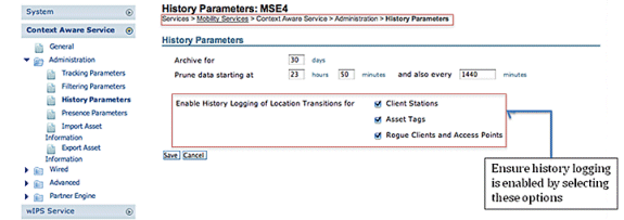
These are important points to note about location history:
-
The history tracking must be enabled (as shown) to retrieve any history information about an element.
-
The number of days of history and pruning time must be properly chosen (see screen shot).
-
Although the number of days to save history is not limited on the UI, the history stored on the server is limited by the disk space and performance impact on the overall system.
-
The history of an element is recorded only if these occur:
-
It moves more than 10m or 30 feet.
-
If the emergency or panic button is pressed on the tags.
-
If the tag passes by an exciter.
-
If the floor changes, that is, the element moves between floors.
-
-
An element is declared “inactive” if it remains inactive for one hour. If it remains inactive for 24 hours, it is removed from the tracking table. Once the element is removed from the tracking table, then it is not possible to see element’s historical location on the WCS monitoring page, although the element’s history is still there in the MSE for 30 days. Absent Data Cleanup Interval entry (see Figure 4), helps to control tracking table.
Figure 4: Location Parameters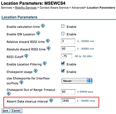
Logging every transition as an event for storage in the historical database and limiting the Location History table to 10 million rows for performance reasons, Table 1 summarizes the number of days it takes to reach that limit. The greater the number of element transitions per minute, the greater the amount of disk space that is consumed. As per the table, it only takes 7.14 days to reach 10 million rows with 1000 transitions/minute. With the default of 30 days of historical data, 1000 transitions/minute consumes excessive disk space since MSE does not delete historical data before the 30-day window has been reached.
Cisco recommends that you change the history parameter for devices that move frequently to a value of less than 30 days.
Table 1: Location History Database Limit| Transitions per minute | Days to hit 10 million rows |
|---|---|
| 100 | 69.44 |
| 200 | 34.72 |
| 300 | 23.15 |
| 400 | 17.36 |
| 500 | 13.89 |
| 600 | 11.57 |
| 700 | 9.92 |
| 800 | 8.68 |
| 900 | 7.75 |
| 1000 | 7.14 |
Chokepoint location — The MSE provides granular and deterministic localization based on the passage of an asset through a constrained physical area known as a chokepoint. Chokepoint triggers (also called “exciters”) located within these areas and in proximity to tagged assets stimulate the tags with low-frequency (125 kHz) signaling. The RFID tags then transmit the identity of the chokepoint trigger to the Cisco UWN infrastructure. The chokepoint information contained in the tag packet provides the MSE with information to override RF Fingerprinting location coordinates and assume the chokepoint position for a given duration. This proximity location accuracy can range from a radius of under one foot to over twenty feet (25 to 650cm), dependent upon the capabilities of the chokepoint trigger. Applications for chokepoint location vary from general-purpose uses, such as theft prevention of high value assets, to industry-specific process control events, such as those used in manufacturing plants.
Cisco Extensions for Wi-Fi Tags telemetry information and emergency notifications — Cisco has partnered with a variety of asset tag vendors to create an extensible specification for 802.11 Wi-Fi-based active asset tags. The Cisco Compatible Extensions (CCX) Wi-Fi Tag specification defines a common transmission format that tag vendors can use to interoperate with the Context Aware Cisco UWN. This includes a baseline feature set that encompasses telemetry, tag transmit power level, battery information, and advanced fields for emergency groups and chokepoints. The addition of an MSE allows customers to take advantage of these capabilities and benefits customers by providing the ability to "mix and match" compliant asset tags from different vendors in the same network. Currently, tag vendors have implemented CCXv1. Tag reference URL: http://www.cisco.com/web/partners/pr46/pr147/ccx_wifi_tags.html.
Section 2: Plan and Setup of Your Context Aware Network
There are several guidelines that need to be followed when you deploy a wireless network that directly impact the level of location accuracy.
Designing the Wireless LAN For Location And Voice
General Guidelines – RSSI
In order to determine the optimum location of all devices in the wireless LAN coverage areas, consider access point density and placement.
Access Point Placement
Proper placement of access points, or perhaps better, placement and type of antenna are several best practices that need to be met in order to experience a reasonable level of location accuracy. In many office wireless LANs, access points are distributed mainly throughout interior spaces and provide service to the surrounding work areas. These access point locations have been selected traditionally on the basis of coverage: WLAN bandwidth, channel reuse, cell-to-cell overlap, security, aesthetics, and deployment feasibility. In a location-aware WLAN design, the requirements of underlying data and voice applications must be combined with the requirements for good location fidelity. Dependent upon the particular site, the requirements of the location-aware Cisco UWN are flexible enough that the addition of location tracking to voice installations already designed in accordance with Cisco best practices, for example, possibly do not require extensive reworking. Rather, infrastructure already deployed in accordance with accepted voice best practices can often be augmented such that location tracking best practice requirements are also met (such as perimeter and corner access point placement, for example) dependent upon the characteristics of the areas involved.
In a location-ready design, it is important to ensure that access points are not solely clustered in the interior and toward the center of floors. Rather, perimeter access points complement access points located within floor interior areas. In addition, access points must be placed in each of the four corners of the floor, and at any other corners that are encountered along the floor perimeter. These perimeter access points play a vital role to ensure good location fidelity within the areas they encircle, and, in some cases, can provide general voice or data coverage, as well.
If you use chokepoint location, verify that all areas planned for chokepoint trigger installation are clearly within the RF range of your access points. Contrary to passive RFID scanners, the tag uses the WLAN to transmit the exciter contents to the infrastructure. In addition to the assurance that messages transmitted by asset tags located within chokepoint areas are properly received by the system, proper planning can help assure that asset tags can be tracked with RF Fingerprinting as they approach and exit chokepoints. The ability to track asset tags with RF Fingerprinting complements the ability of the system to locate tagged assets within chokepoint areas with highly granular chokepoint location techniques.
The access points that form the perimeter and corners of the floor can be thought of as outlining the convex hull or set of possible device locations where the best potential for high accuracy and precision exists. The interior area (area inside of the convex hull) can be considered as possessing high potential for good location accuracy. As tracked devices stray into the area outside the convex hull, accuracy deteriorates.
In order to assure proper convex hull establishment around the set of location data points that possess a high potential for good accuracy, access points must be placed in each corner of the floor, as well as along the floor perimeter between corners. Inter-access point separation along the perimeter must be in accordance with the general access point separation guidelines (described in a subsequent section). The designer can reduce this spacing if necessary, in order for these access points to provide voice or data service to the floor.
Ensure that no fewer than three access points provide coverage to every area where device location is required. Optimal accuracy requires four or more APs. This also reduces the risk of APs not always contributing to location due to other WLAN activities. In a normal office environment, access points must surround the location of any Wi-Fi device that is tracked. An access point must be placed every 40-70 linear feet (~12-20 meters). This translates into one access point every 2,500 to 5,000 square feet (~230-450 square meters). As an example, in a 200,000 ft2 facility, 40 APs (200,000/5,000) are required for proper Wi-Fi coverage. AP antennas must be placed at a minimum height of 10 feet and a maximum height of 20 feet. Because these guidelines depend greatly on the building construction and materials used, other factors and recommendations must be taken into consideration. As a general rule -75dBm must be used as the minimum signal level for device tracking from a minimum of three APs on the same floor.
If you follow these guidelines, it is more likely that access points will detect tracked devices successfully.
Rarely do two physical environments have the same RF characteristics. Users need to adjust those parameters to their specific environment and requirements.
These are the basic rules for AP placement that contribute to location accuracy:
-
Provide AP perimeter coverage.
-
Ensure sufficient AP density.
-
Stagger APs, particularly in long and narrow coverage areas.
-
Design wireless network for all applications (data, voice, and location).
-
Verify wireless deployment with a site survey.
-
In a building with similarly shaped floors, deploy the APs on each floor in a similar pattern. This improves the floor separation performance of the system.
The WCS Planning Tool can be used to determine/verify the proper AP placement and density.
-
Place access points along the periphery and in the corners of coverage areas to help locate devices close to the exterior of rooms and buildings. Access points placed in the center of these coverage areas provide good data on devices that otherwise appear equidistant from all other access points (see Figures 5 through 8) .
Figure 5: Access Points Clustered Together Can Result in Poor Location Results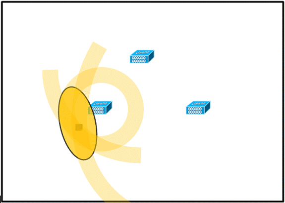
AP:

Wi-Fi Device:

RF Jitter (possible location):

-
Increase overall access point density and move the access points towards the perimeter of the coverage area to greatly improve location accuracy (see figure).
Figure 6: Improved Location Accuracy Through Proper AP Placement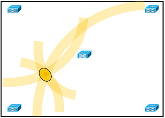
-
In long and narrow coverage areas, do not place access points in a straight line (see Figures 7 and 8).
A preferred deployment is to stagger APs since they provide a unique RF signature to any point on the Wi-Fi coverage map. A straight-line deployment provides a mirror-like RF map. With this type of deployment, the RF signature of a point in the upper side of the map looks very similar to the RF signature at the mirror point on the lower side of the map.
Figure 7: Avoid Deployment of APs in a Straight Line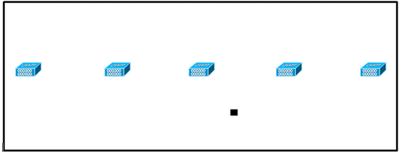
Though the design in Figure 7 can provide enough access point density for high bandwidth applications, the location suffers because the view of a single device of each access point is not varied enough, so the location of the device is difficult to determine.
Move the access points to the perimeter of the coverage area and stagger them. Each is more likely to offer a distinctly different view of the device, which results in higher location fidelity (see Figure 8).
Figure 8: Improved Location Accuracy by Staggering APs Around Perimeter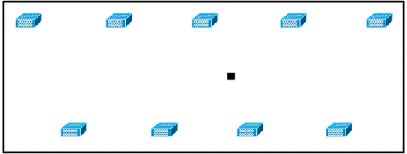
-
When you design a wireless LAN for Context Aware Mobility Solution, while planning for voice as well, you must account for a number of design factors. Most current wireless handsets support only 802.11b, which only offers three non-overlapping channels, so wireless LANs designed for telephony tend to be less dense than those planned to carry data. Also, when traffic is queued in the Platinum QoS bucket (typically reserved for voice and other latency sensitive traffic), lightweight access points postpone their scanning functions that allow them to peak at other channels and collect, among other things, device location information. As such, the user has the option to supplement the wireless LAN deployment with access points set to monitor-only mode. Access points that only monitor do not provide service to clients and do not create any interference. They simply scan the airwaves for device information (see Figures 9 and 10).
Figure 9: Less Dense Wireless LAN Installations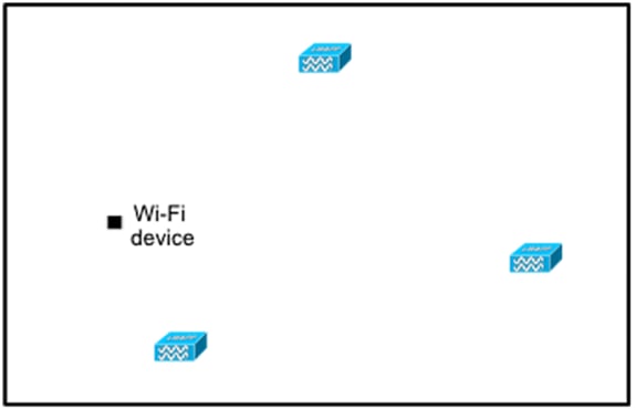
Less dense wireless LAN installations, such as those of voice networks, find their location fidelity greatly increased by the addition and proper placement of Location Optimized Monitor Mode access points.
-
Perform a coverage verification with a wireless laptop, handheld, and possibly a phone to ensure that no fewer than three access points are detected by the device. In order to verify client and asset tag location, ensure that the WCS reports client devices and tags are within the specified accuracy range (10m, 90%). Calibration can be required to reach this level accuracy.
Tracking Optimized Monitor Mode (TOMM)
Starting with software version 5.0, Cisco Aironet 1100 and 1200 APs can operate as Tracking Optimized Monitor Mode APs. This feature can be used for these reasons:
-
Location and voice co-existence: With monitor mode AP in a mixed deployment, there is no negative impact on voice since the location needs increased the AP density.
-
Low touch does not impact present infrastructure.
Tracking Optimized Monitor Mode for location can be used when you track clients and/or tags.
TOMM APs are good to improve coverage for tracking locations regardless of where Wi-Fi coverage gaps exist, either in the perimeter or within the convex hull. TOMM APs do not interfere with local mode AP operation. In order to optimize monitoring and location calculation of tags, TOMM can be enabled on up to four channels within the 2.4GHz band (802.11b/g radio) of an access point. This provides the ability to focus channel scans only on those channels on which tags are usually programmed to operate (such as channels 1, 6, and 11).
Figure 10: Tracking Optimized Monitor Mode AP deployment 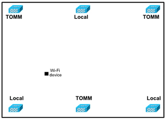
AP and Antenna Placement
The positioning of APs and external antennas can have a dramatic impact on the performance of wireless network. This is true for data and voice transmission, as well as location tracking. APs and antennas must not be placed in a location (such as near I-beams) that can potentially distort signal patterns. An RF null point is created by the crossing of signal waves, and multipath distortion is created when RF signals are reflected. This placement results in very little coverage behind the AP and reduced signal quality in front of the AP. An I-beam creates many reflections for both received and transmitted packets. The reflected signals result in very poor signal quality because of null points and multipath interference, but the signal strength can be high because the AP antennas are so close to the I-beam that it can amplify the signal. Instead, the AP and antenna placement must be positioned away from I-beams so that there are fewer reflected signals, fewer null points, and less multipath interference. The principle also applies when placing APs and antennas in or near the ceiling in a standard enterprise environment. If there are metal air ducts, elevator shafts, or other physical barriers that can cause signal reflection or multipath interference, Cisco recommends that antennas be placed away from such objects. In the case of large metallic objects, such as elevators and air ducts, move the antenna a few feet away. This helps eliminate the signal reflection and distortion. Figures 11 through 13 depict poor AP placement.
Figure 11: Poor AP Placement - AP Placed Near Physical Obstruction 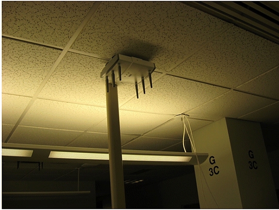
When you install access points with either internal or external antennas, both the placement of the access point, as well as the orientation chosen for the access point antennas in WCS must match the actual physical access point placement and antenna orientation. This ensures accuracy and precision in both location tracking, as well as the display of predictive heat maps. The antenna type, position, orientation, and height from the floor are critical to ensure good accuracy. When you place the APs in WCS, ensure that antenna orientation and type match what is deployed.
Note: When you track wireless clients, only Cisco antennas are officially supported. For non-Cisco antennas, heatmaps are not generated in WCS. This also means that RSSI values received from these antennas are ignored at location calculation. For tag tracking, both Cisco and non-Cisco antennas can be used.
The typical Cisco Aironet access point is installed with antenna diversity. Antenna diversity helps ensure optimal range and throughput in high multipath environments. It is recommended that antenna diversity always be enabled. The Context-Aware Cisco UWN is designed to take RSSI information from both access point antennas into account when you localize tracked devices. For good accuracy, ensure that antennas are physically present on all enabled access point antenna ports. Failure to do so can cause irregular RSSI readings to be reported on enabled antenna ports that do not have an attached antenna. The abnormally low RSSI values from antenna ports without antennas result in poor location accuracy.
The choice of antenna choice for use with an AP is vital to the characteristics of any wireless network deployment. Essentially, two broad types of antenna exist: directional and omni-directional. Each type of antenna has a specific use and is better suited for a specific type of deployment. Because antennas distribute RF signal in large lobed coverage areas determined by antenna design, successful coverage is heavily reliant on antenna choice.
An antenna has three fundamental properties: gain, directivity, and polarization.
-
Gain: A measure of the increase in power. Gain is the amount of increase in energy that an antenna adds to an RF signal. All antennas are passive elements. Power is not added by an antenna but redistributed to provide more radiated power in a given direction than is transmitted by an omni-directional (isotropic) antenna. If an antenna has a greater than gain of 1 in given direction, it must have a less than a gain of 1 in other directions since energy is conserved by the antenna.
-
Directivity: The shape of the transmission pattern. If the gain of the antenna goes up, the coverage area decreases. The coverage area or radiation pattern is measured in degrees. These angles are measured in degrees and are called beamwidths.
Note: Beamwidth is defined as a measure of the ability of an antenna to focus radio signal energy towards a particular direction in space. Beamwidth is usually expressed in degrees HB or Horizontal Beamwidth, usually the most important one with VB as the Vertical Beamwidth (up and down) radiation pattern. When you view an antenna plot or pattern, the angle is usually measured at half-power (3 dB) points of the main lobe when referenced to the peak effective radiated power of the main lobe.
-
Polarization: The orientation of the electric field of the electromagnetic wave through space. Antennas can either be horizontally or vertically polarized, though other kinds of polarization are available. Both antennas in a link must have the same polarization to avoid additional unwanted signal loss. In order to improve performance, an antenna can sometimes be rotated to alter polarization and thus reduce interference. A general rule of thumb is that vertical polarization is preferable to send RF waves down concrete canyons, and horizontal polarization is generally more preferable for wide area distribution. Polarization can also be harnessed to optimize for RF bleed-over when reduction of RF energy to adjacent structures is important. Most omni-directional antennas ship with vertical polarization as their default.
The radio energy radiated from an antenna is called the Effective Isotropic Radiated Power (EIRP). The EIRP value is usually expressed in Watts or dBm. In order to enable fair and equitable sharing of the unlicensed band, regulatory domains impose maximum EIRP levels. Since the EIRP is a measure of the power out of the antenna, the EIRP must include the antenna gain and the cable loss together with the power out of the transmitter. Antenna cables can add loss, which leads to attenuation of the transmitted signal. The longer the cable, the greater the attenuation and the more the signal loss in the cable, which affects both receive and transmit power. Cable attenuation is dependent upon the grade and manufacturer. Low-loss cable is typically around 6.7 dB per 100 ft (30m) at 2.4GHz.
Signal Attenuation
Signal attenuation or signal loss occurs when an RF signal passes through any medium. Signal attenuation varies based on the type of material a signal passes through. Table 2 provides signal loss values for various objects.
Table 2: Signal Attenuation Values Through Various Objects| Object in Signal Path | Signal Attenuation Through Object |
|---|---|
| Plasterboard wall | 3 dB |
| Glass wall with metal frame | 6 dB |
| Cinder block wall | 4 dB |
| Office window | 3 dB |
| Metal door | 6 dB |
| Metal door in brick wall | 12 dB |
| Human body | 3 dB |
Note: This is only a rough guide; different countries have various building regulations. The different regulations apply to the maximum EIRP allowed, as well as other parameters.
A transmit power of 20 mW is equivalent to 13 dBm. If the transmitted power at the entry point of a plasterboard wall is at 13 dBm, the signal strength is reduced to 10 dBm when it exits that wall.
Site surveys conducted at different types of facilities display different levels of multipath distortion, signal loss, and signal noise. Hospitals are typically the most challenging environment to survey due to high multipath distortion, signal losses, and signal noise. Hospitals generally take longer to survey and probably require a denser population of APs. Manufacturing and shop floors are also challenging environment s in which to conduct site surveys. These sites generally have a high metal content in their building structure that results in reflected signals that recreate multipath distortion. Office buildings and hospitality sites generally have high signal attenuation but a lesser degree of multipath distortion. The only way to determine the distance an RF signal travels in a given environment is to conduct a proper site survey.
Note: It is important to take into consideration the Rx signal level on the AP and devices tracked and not so much that of the client that collects the site survey data. A good rule of thumb is to have the APs set to a relatively high power setting, for example, 50mW, when you perform a site-survey. Because most antennas have symmetrical Tx/Rx characteristics, the resultant coverage patterns reflect the approximate RSSI of the APs
Surveyance of Multi-Floor Buildings, Hospitals, and Warehouses
There are numerous factors that need to be taken into account when you survey multi-floor buildings, hospitals, and warehouses.
It is important to find as much detail as possible in regard to the building construction. Some examples of typical construction methods and materials that affect the range and coverage area of APs include metallic film on window glass, leaded glass, steel-studded walls, cement floors and walls with steel reinforcement, foil-backed insulation, stairwells and elevator shafts, plumbing pipes and fixtures, and many others. Also, various types and levels of inventory can affect RF range, particularly those with high steel or water content. Some items to watch for include printer paper, cardboard boxes, pet food, paint, petroleum products, engine parts, and so forth. Ensure that the site survey is conducted at peak inventory levels or at times of highest activity. A warehouse at a 50% stocking level displays a very different RF footprint than the same facility that is completely occupied.
Similarly, an office area that is not populated has a different RF footprint than the same area when occupied. Although many parts of the site survey can be conducted without full occupation, it is essential to conduct the site survey verification and tweak key values at a time when people are present and normal activity takes place.
The higher the utilization requirements and the higher the density of users, the more important it is to have a well-designed diversity solution. When more users are present, more signals are received on the device of each user. Additional signals cause more contention, more null points, and more multipath distortion. Antenna diversity on the AP helps to minimize these conditions.
Keep these guidelines in mind when you conduct a site survey for a typical multi-floor office building:
-
Elevator shafts block and reflect RF signals.
-
Supply rooms with inventory absorb RF signals.
-
Interior offices with hard walls absorb RF signals.
-
Break rooms (kitchens) can produce 2.4GHz interference caused by microwave ovens.
-
Test labs can produce 2.4 GHz or 5 GHz interference. The problem of interference is that it increases the noise floor and decreases the SNR (signal to noise ratio) of the received signal. A higher noise floor reduces the effective range of the APs.
-
Office cubicles tend to absorb and block signals.
-
Class windows and partitions reflect and block RF signals.
-
Bathroom tiles can absorb and block RF signals.
-
Conference rooms require high AP coverage because they are a high Wi-Fi utilization area.
When you survey multi-floor facilities, APs on different floors can interfere with each other as easily as APs located on the same floor. This can be beneficial for voice and/or data deployments, but it causes problems when you deploy Context Aware. Floor separation is critical for this solution to function properly. In multi-tenant buildings, there can be security concerns that require the use of lower transmission powers and lower gain antennas to keep signals out of nearby rooms or offices. The survey process for a hospital is much the same as that for an enterprise, but the layout of a hospital facility tends to differ in these ways:
-
Hospital buildings often have recurrent reconstruction projects and additions. Each additional construction can require different construction materials with different levels of signal attenuation.
-
Signal penetration through walls and floors in the patient areas is typically minimal, which helps create micro-cells. Consequently, AP density needs to be much higher in order to provide sufficient RF coverage.
-
The need for bandwidth increases with the increased usage of WLAN ultrasound equipment and other portable imaging applications.
-
Due to the requirement for higher AP density, cell overlap can be high, which results in channel reuse.
-
Hospitals can have several types of wireless networks installed, which includes 2.4 GHz non-802.11 equipment. This equipment can cause contention with other 2.4 GHz or 5 GHz networks.
-
Wall-mounted diversity patch antennas and ceiling-mounted diversity omni-directional antennas are popular, but keep in mind that diversity is required.
Warehouses have large open areas, that often contain high storage racks. Many times these racks reach almost to the ceiling, where APs are typically placed. Such storage racks can limit the area that the AP can cover. In these cases, consider placing APs on other locations besides the ceiling, such as side walls and cement pillars. Also consider these factors when you survey a warehouse:
-
Inventory levels affect the number of APs needed. Test coverage with two or three APs in estimated placement locations.
-
Unexpected cell overlaps are likely because of coverage variations. The quality of the signal varies more than the strength of that signal. Clients can associate and operate better with APs farther away than with nearby APs.
-
During a survey, APs and antennas usually do not have an antenna cable that connects them, but in a production environment, the AP and antenna can require antenna cables. All antenna cables have signal loss. The most accurate survey includes the type of antenna to be installed and the length of cable to be installed. A good tool to use to simulate the cable and its loss is an attenuator in a survey kit.
When you survey a manufacturing facility, it is similar to the surveillance of a warehouse. One key difference is that the ambient RF environment is much noisier in a manufacturing facility because of many more sources of RF interference. Also, applications in a manufacturing facility typically require more bandwidth than applications used in a warehouse environment. These applications can include video imaging and wireless voice. Multipath distortion is likely to be the greatest performance problem in a manufacturing facility.
It is important that the site survey not only measures signal levels but also generates packets and then reports packet errors in order to properly characterize the RF environment.
For areas where user traffic is high, such as office spaces, schools, retail stores, and hospitals, Cisco recommends that you place the AP out of sight and place unobtrusive antennas below the ceiling.
Location Rails and Regions
The deployment guidelines given yield a good level of accuracy: 10m/90%, 5m/50%. The 10m/90% value corresponds to a 10m radius from the actual physical location of a given device, so there will be cases where these accuracy targets are met, but the device that is tracked can show up in areas on floor and/or building levels where devices cannot be present.
The Rails and Regions feature provides a mechanism for a network administrator to define inclusion/exclusion areas for location services. This feature allows for specific regions on a map to be defined as within or outside the scope of valid location area.
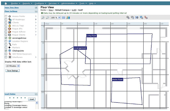
Three types of regions can be specified as shown in Figure 14:
-
Location inclusion region: tracked device cannot be outside this polygon (example: outside of building outer walls)
-
Location exclusion region: tracked device cannot be inside this polygon (examples: open atrium or building obstructions). Exclusion is given preference over inclusion in the event that conflicting regions are drawn.
-
Rails: tracked device must be within defined area with narrow band, typically used within exclusion region (example: conveyor belt).
After the Rails and Region areas have been defined in WCS, the floor update needs to be pushed from WCS to the MSE through the synchronization process.
Note: On the MSE, Location Rails and Regions only work with Context Aware Engine for Clients. AeroScout has implemented a feature called Cells and Masks that provides similar functionality when you track tags. For the Cisco 2710 Location Appliance, the Rails and Regions feature works with both client and tag tracking.
Figure 14: Rails and Regions 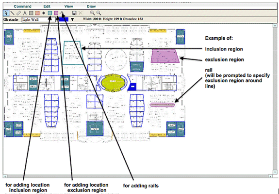
Create a Mask in the System Manager
A mask is defined by drawing a polygon on a map that delimits the area to exclude.
Complete these steps to create a mask:
-
Choose Configuration, Maps, Mask, and Edit Mask.
This switches the system to the mask editing mode. The mouse pointer changes to a cross.
-
Click a point on the map; slide the mouse to the next point, click again, and repeat this process to mark the vertices of the polygon (see Figure 15).
Figure 15: Creating a Mask - Marking the vertices of the polygon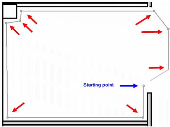
When you slide the mouse to the starting point, in order to close the polygon, a purple circle appears, which indicates the closing point (see Figure 16).
Figure 16: Creating a Mask - Purple circle indicating the closing point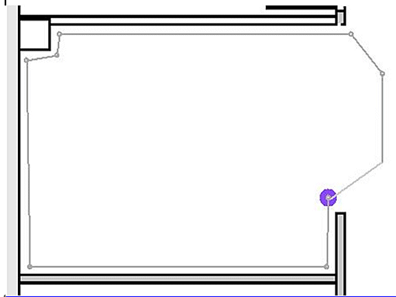
Click to finalize the mask definition. The mask appears on the map (see Figure 17).
Figure 17 : Creating a Mask - Mask appears on the map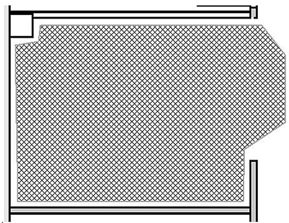
-
Right-click anywhere on the map, and choose Exit Mask Drawing Mode (or press Esc) to exit the mask editing mode.
By default, the mask is removed from the display after it exits the mask drawing mode. In addition, to enable / disable or edit masks, refer to Aeroscout Documentation
 for more information.
Cells in Context-Aware Engine for Tags
Cells are designed to divide a map into smaller portions in order to optimize the location calculation process and improve positioning accuracy. The cell defines the geographical boundaries for the positioning of a tag. It also defines which specific devices (TDOA receivers and access points) take part in the location calculation process within those boundaries.
The cell mechanism is used for both RSSI and TDOA location calculations.
The Engine processes inbound location data:
-
A report that indicates the location of a tag can come from multiple access points or Wi-Fi TDOA receivers at once. The map-differentiation algorithms of the engine choose the map where the device is most likely to be located and discard location reports that point to other maps.
-
Once the map is determined, the engine looks for cells. If the map is divided into cells, the same optimization mechanism chooses the cell the TDOA receivers/access points of those that most likely delivered the most accurate location report. The location of the device is then calculated according to the data received from the TDOA receivers/access points associated with that cell and within the boundaries of that cell.
Note that the TDOA receivers/access points associated with a cell do not have to be necessarily inside the area delimited by the cell boundaries.
Initial Operation for Cells Configuration
Initially a default cell is created automatically for each map to cover the entire map area. In order to split the map into separate cells, perform these operations:
-
Edit the default cell to cover only a subset of the map area (see instructions to modify a cell).
-
Add more cells to the map as required. Note that a cell cannot be entirely included within another cell.
-
Go over the properties of each location device (access points and TDOA receivers), and associate the device with proper cells.
-
The associated devices of a cell cannot be a subset of the associated devices of another cell. Make sure that each cell has devices associated with it that are not associated with any other cell.
Calibration – Context Aware Engine for Clients
Location Accuracy is dependent on two main factors:
-
AP placement and number of APs that contributes to location
-
Correct RF signal characteristics of an AP for given environment (accurate AP heat maps)
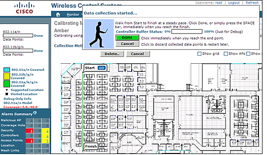
Within the calibration phase, data is gathered on the WCS server when a walk-around of the target environment with a mobile device is performed that allows multiple APs to sample the signal strength of this device. The recommended method is to use single or multiple laptops logged into WCS (maximum of five devices per radio band), and choose a map of the area to be calibrated, which is typically overlaid with a set of grid points or notations to guide the operator to determine precisely where sample data must be acquired. At each sample point on the map, the set of RSSI values associated with the calibration device is forwarded by the WLC to the MSE. The size of a given data set is based on the number of receiving Access Points that detect the mobile device. Because of fading and other RF environment characteristics, the observed signal strength of a mobile device at a particular location is time variant, that is, it can change over time. Consequently, many data samples are recorded for a calibration device within the calibration process.
Each environment is unique, and signal characteristics of an AP in a given environment vary widely. WCS provides a mechanism for a user to calibrate signal characteristics for their environment. The first step to optimize accuracy is to ensure that the AP deployment is in accordance with the location deployment guidelines summarized. An attempt to improve location accuracy with calibration with inadequate AP coverage and placement possibly does not provide adequate results and can even be detrimental to accuracy.
Three default calibration models are provided with WCS:
-
Cubes and walled offices
-
Drywall office only
-
Outdoor open space
Each model is based on the most common factors in a typical customer environment. The first of these two RF models is useful in a normal office environment.
If the provided RF models do not sufficiently characterize the floor layout, calibration models can be created with WCS and applied to the floor to better represent the attenuation characteristics of a given environment. In environments where many floors share common attenuation characteristics, one calibration model can be created and then applied to all similar floors.
Some indoor environments can possess more attenuation than what is found in a typical office environment. In properly designed indoor installations where increased attenuation can be a factor in contributing to less than optimal location accuracy, a site calibration can help restore less than optimal performance. When an on-site calibration is performed, the system is allowed to sample path losses from known points throughout the environment, which allows it to formulate a custom RF model that provides a better understanding of the propagation characteristics specific to that environment.
In many cases, use of the information collected at calibration instead of a default model can dramatically reduce the error seen between calculated client location and empirical data. In environments where many floors share almost identical attenuation characteristics, strong similarities between these locations allow for the RF model created by calibration performed on any one of the locations to be applied to other similar areas with good results.
Consideration must also be given to areas of mixed RF attenuation, that is, manufacturing or warehouses where there can be stacked goods or dense obstruction in one area of the building and/or open spaces used for assembly or shipping. These areas must be treated as independent zones that restrict calibration to the areas where highest accuracy is required. If highest accuracy is required for all these zones in a mixed area, it is advisable to break the floor area into individual cells or maps and apply separate RF models.
Note: The performance of this type of RF modeling is complex and requires further deployment considerations, which are outside the scope of this document.
Calibration is actually a multi-step process that begins with the definition of a new calibration model through Monitor > Maps > RF Calibration Models > Create New Model. For a step-by-step description of the calibration process, refer to Creating and Applying Calibration Models in the Cisco Context-Aware Software Configuration Guide.
Within the calibration process, the calibration client repeatedly transmits probe requests on all channels. Dependent upon the particular calibration client used, the client can be triggered to transmit probe requests on-demand through a network request. Clients that cannot recognize these requests can be de-authenticated and disassociated in order to cause them to issue probe requests to the wireless network and subsequently re-associate/re-authenticate. Access points in the vicinity of the client detect the RSSI of these probe requests and pass this information to their registered controllers. Controllers provide the RSSI information that is detected within the calibration process to the WCS for use in computing the path losses that are used to define the new calibration model.
When you create a calibration model, the critical step is to collect the data points. The data point collection phase of the calibration process in WCS can be performed with one of two methods. It can be performed from a single web-enabled mobile device associated to the WLAN, which controls both the probing of the network, as well as the actual data collection. Alternatively, the data collection phase can be performed from two separate devices that are associated to the WLAN infrastructure. In this case, interaction with the WCS GUI is controlled from a primary device that is equipped with keyboard and mouse capabilities, while the actual generation of probe requests occurs on a second associated device when you choose its known MAC address.
It is recommended that calibration data collection be performed for each band individually. When you use a dual-band client, use either of these alternatives:
-
Perform the calibration data collection with a single laptop equipped with a Cisco Aironet 802.11a/b/g Wireless CardBus Adapter (AIR-CB21AG) on each band individually. When you perform calibration exercise for 2.4 GHz band, disable the 5 GHz band and complete the data collection with the 2.4 GHz band only. After this calibration process has been completed, disable the 2.4 GHz band, enable the 5 GHz band, and repeat the calibration data collection process with the 5 GHz band.
Note: In a production environment where it proves difficult to choose the PC radio band, it is preferable to define a specific calibration SSID with only 11b/g or 11a active.
-
Perform the calibration with up to five clients per radio band - each equipped with a laptop. Each laptop must have a Cisco AIR-CB21AG and be associated to the infrastructure with a dedicated band. Each calibration client can operate independently.
Before you perform a calibration, several pre-configuration steps are required:
-
In a production environment, inform the staff or workers of the process. This reduces interruption and ensure a higher degree of accuracy. Decrease the risk of accidents especially in manufacturing plants where forklift trucks are in operation.
-
Disable dynamic RRM AP power mode on the controller(s) or APs where you perform the calibration.
-
Confirm that maps on the WCS are to scale and APs have been positioned correctly with correct antenna type orientation and height.
-
The PC or device used for calibration is associated to an AP located on the MAP in question.
-
The Wireless client used for calibration needs to be a minimum of CCXv2. Cisco recommends CCXv4 for best results. The CCX version information for clients can be viewed in WCS (see Figure 18).
Figure 18: Checking CCX version of clients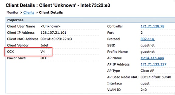
-
Cisco Secure Services Client (CSSC) must not be used to run calibration.
-
At least 50 data points must be collected on a floor map.
-
After you create the calibration model and apply this model to the floor map(s), WCS must be synchronized with MSE.
In the case of multi-floor building, the calibration data collection exercise must be completed on one floor at a time. Since there is the possibility that a calibration client can see and be seen by APs on adjacent floors due to RF bleeding between floors, the collection of calibration data one floor at a time minimizes the risk that the MSE mixes calibration data between floors.
When a client that is compatible with the CCXv2 or greater is associated to the WLAN infrastructure and is specified as the calibration client in WCS, the MAC address of the client is inserted into the location calibration table of all controllers that service the access points contained on the calibrated floor. This insertion initially occurs immediately after the MAC address of the calibrating client, calibration campus, building, and floor are specified. After each save of a collected data point, the client MAC address is removed from the location calibration table of the controller. The client MAC address is then briefly reinserted into controller location calibration tables upon each subsequent data point save and immediately removed thereafter. This process repeats for each data point collected.
When the MAC addresses of CCXv2 (or greater) clients appear in the location calibration table of a WLC, unicast Radio Measurement Requests are sent to these clients. Similar to how broadcast Radio Measurement Requests help improve the location accuracy of compatible clients within normal operation, unicast Radio Measurement Requests sent at short regular intervals (4 seconds) cause compatible calibration clients to transmit probe requests frequently. The use of CCX Radio Measurement Requests and CCXv2 or greater clients allows this to occur without the need to force the client to continually disassociate and re-associate. This allows more consistent and reliable probing of the network, and allows smoother operation of the calibration client, especially if it is used as a workstation that interacts with WCS through the calibration data collection GUI.
A calibration model is applied to the floor and better represents the attenuation characteristics of that floor. In environments in which many floors share common attenuation characteristics, one calibration model can be created and then applied to floors with the same physical layout and same deployment.
Calibration data can be collected with one of two methods:
-
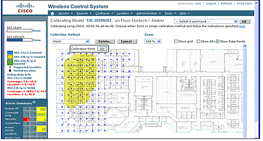
Point mode collection — Calibration points are chosen and their coverage area is calculated, one location at a time (see Figure 19 and 20).
-
Linear mode collection — A series of linear paths is chosen and then calculated as you traverse the path. This approach is generally faster than the data point collection. You can also employ data point collection to augment data collection for locations missed by the linear paths (see Figure 21).
Although both of these methods are officially supported, Cisco recommends that you use the Point Mode for calibration because this yields the best results.
Figure 19: Calibration—Point Mode 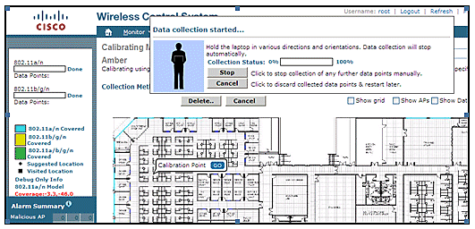
Calibration models can only be applied to clients, rogue clients, and rogue access points. Calibration for tags is done with the AeroScout System Manager.
Calibration—Context Aware Engine for Tags
There are two location engines on the MSE: one to track clients (Cisco engine described in the previous section) and one to track tags (AeroScout). Each engine has a separate calibration model, so calibration for tags is a separate process.
The AeroScout engine assumes the typical office default RF Path Loss model for all the imported WCS maps. If this does not represent your environment, changes must be made to the default models per map and or cell to improve location accuracy.
AeroScout System Manager — In order to modify the default Path Loss Model (PLM) settings, it is necessary to install and run the AeroScout System manager application. For downloading and installation, refer to AeroScout Documentation.
After you start the application, log on to the MSE engine, switch to the actual map floor, which needs modification. Use the pull-down tab and go toconfiguration > Map > properties. The RSSI Location Calculation Options can be used to choose the fixed environmental type appropriate to the physical specifications represented by the four defined models shown in the Figure 22. After you choose the model, apply it to the chosen floor. Use the OK tab or the option to Synchronize all RSSI Devices with Global Parameters, which pushes the same model to all existing maps as the new default model.
Note: The fifth option, “Custom,” must only be used when requested by AeroScout or Cisco technical support.
Figure 22: Models available in AeroScout Systems Manager 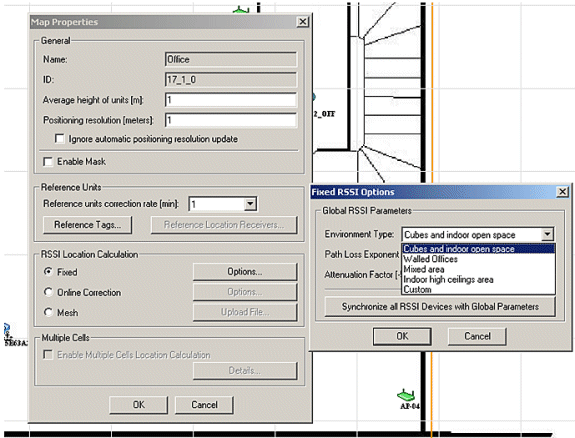
Calibration Methods—Several options are available with individual tags as static reference devices or if periodical or one-off recordings are performed, which can be used to analyze and calculate precise models per map/cell.
Reference Tags—These are standard tags used for asset tracking. The only difference, if any, is the configuration. Normally a reference tag uses a faster beacon period for a defined measurement interval.
Reference tags can be defined with the MAC address, as shown in Figure 23, and placed directly on a cell or map shown by a blue anchored tag. The coordinates can be entered manually by a right mouse click on the map. Reference tags used for dynamic adaption of location require to be enabled in the reference tag selection box under Map Properties > Reference Units (see Figure 22). This method of calibration is described for TDoA.
Figure 23: Reference Tag Properties 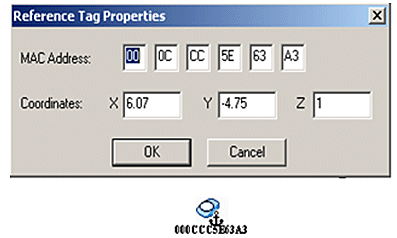
Single-Click recording—A more preferred method for calibration is the Single-Click recording operation. This defines a group(s) of tags and places them on the map for a short preset time period. A recording is initiated, and the captured data is stored directly on the MSE based on timestamp and map identification.
Best results are obtained when the reference group of tags is arranged in a compact order mounted on a small cube or a pole. The same group can be repositioned and the procedure repeated multiple times on the same map if you reposition the group and restart the recording with one mouse click. Alternatively, multiple groups can be defined on the same map and recorded in one sequence.
Figure 24: AeroScout Systems Manager Tools 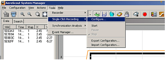
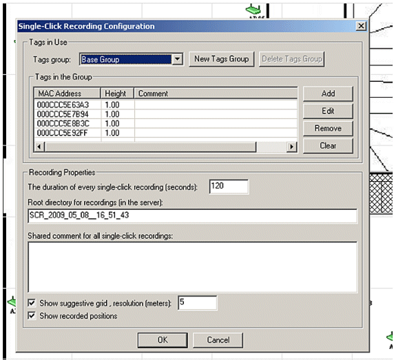
In order to perform this method, enter the configuration information found under Tools > Single-Click Recording shown in Figures 24 and 25. Recording properties can be modified if the default values are not appropriate. The recordings are automatically stored in subdirectories based on the time and date of the recording.
Analyzer Tool—Before the Single-Click recording data can be used for calibration, it must be viewed and converted into a Mesh file. With the System Manager, the recorded data files stored on the MSE need to be exported to the system where the analyzer tool can be used to view and modify the recorded data, if necessary, before it creates a Mesh file. The resultant Mesh file is imported back to the MSE, where it can be applied to the map properties if you choose the RSSI Location Calculation Mesh together with the upload file choice.
For a detailed explanation, refer to the AeroScout Documentation for further configuration information and the calibration process.
Refer to the AeroScout Mesh File Generation in AeroScout Documentation.
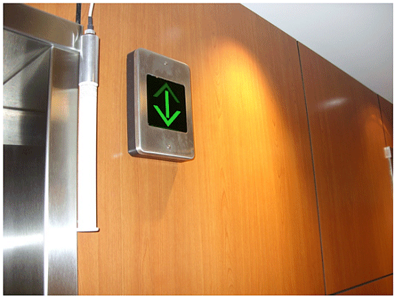
Exciter (Chokepoint Trigger) Technology
Exciters are proximity communication devices that trigger asset tags to alter their behavior when an asset tag enters the proximity of an exciter. This alteration can cause the RFID tag to transmit its unique identifier or cause the tag to change its internal configuration or status. One of the prime functions of a chokepoint trigger is to stimulate the asset tag such that it provides indication to the MSE that the tag has entered or exited a given area. Chokepoints are entry or exit points that provide passage between connected regions. Common chokepoints are doorways, hallways, and stairwells. Indoor chokepoint locations include connecting entrances or exits.
Exciters do not use triangulation so do not require signals to be detected by a minimum of three APs.
Exciters can initiate behavioral changes in tags that can immediately alert the location system that the tagged asset has entered or exited the chokepoint area. The RFID tags then transmit the identity of the chokepoint trigger to the Cisco UWN infrastructure. The chokepoint information contained in the tag packet provides the MSE with information to override RF Fingerprinting location coordinates and assume the chokepoint position for a given duration.
Best practices to configure and tune exciters and tags can be found in the Exciter and Tag Configuration Guide from AeroScout Documentation.
Considerations for Deploying Context Aware with Existing Data and Voice Services
In customer office environments where existent wireless networks are in place, overlaying Context Aware Mobility Solution require you to re-evaluate the overall deployment for accuracy and potential coverage holes. These are general guidelines to be followed:
-
Maximum effective access point spacing in most site-office environments: 40-70 feet (12 to 21 meters)
-
Minimum of 3 APs within the transmission range of every client (recommend 4 APs for redundancy)
-
Place perimeter APs first since access points must surround the desired areas of location coverage
-
Next place interior APs to minimize coverage gaps for a minimum of -75dBm
-
In quadrilateral area, a minimum of 4 APs must be installed at the four corners of the area
-
Factors that affect accuracy: AP placement, wall materials, large moving objects, and RF interference
-
Possibly need to divide floor space into sub-areas and design sub-areas independently to account for large barriers that obstruct RF signals (see Figure 26). Up to 50 coverage areas for floor are supported. Coverage area size cannot be smaller than the typical location range (~10m)
-
APs preferably are positioned along and within the perimeter of an enclosed area.
-
APs must be distributed evenly, that is, APs must be relatively equidistant from each other.
-
Physical placement of APs must be non-collinear, even when placed at equal distances from each other.
-
Use the Location Readiness Tool in WCS to gauge the effectiveness of overall floor coverage.
-
Geometric shapes formed by the distribution of APs affect accuracy:
-
Equilateral triangle placement yields better accuracy than APs that form an obtuse triangle.
-
Square deployment placement yields better results than APs that form rectangles.
-
Figure 27 illustrates the concept of cell overlap for a Cisco 7921G VoWLAN handset using 802.11bg. For the Cisco 7921G, the recommended best practices found in the Voice Over Wireless LAN Design Guide recommends that the cell-to-cell overlap should be approximately 20% when using 802.11bg and approximately 15% when using 802.11a.
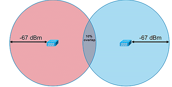
Data applications do not display the same level of sensitivity to packet loss as voice applications. Consequently, they do not require the same degree of cell-to-cell overlap as VoWLAN deployments. In most cases, a minimum 10% cell-to-cell overlap is sufficient for reliable roaming with data applications, as shown in Figure 28. High speed data applications and applications combining voice and data capabilities in a single device (smartphones, for example) might require cell-to-cell overlap that resembles a VoWLAN design much more than a data design.
Figure 27: Inter-Cell Overlap—Voice and Data Deployment (20% Cell Overlap) 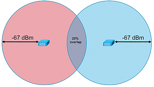
General Guidelines – TDOA
With TDOA-based deployment, a minimum of three receivers is required, but four receivers yield more accurate results. These are the general rules for TDOA receiver density:
-
Outdoors—average density is one TDOA receiver for every 20,000 - 50,000 sq ft. (1,900 - 4,700 sq m).
-
Large indoor areas—average density is one TDOA receiver every 5000 – 14,000 sq ft. (450 - 1,300 sq m).
-
Distance between synchronized source and TDOA receivers is less than or equal to 150m for outdoor deployments.
-
Distance between synchronized source and TDOA receivers is less than or equal to 70m for large indoor deployments.
Two important considerations for TDOA: receiver density deployment depends on receiver synchronization and the RF coverage Rx sensitivity of the tracked devices. The second important consideration is to have enough coverage of the location receivers to ensure a receptive density of at least three location receivers at any point in the location area.
In certain scenarios, large areas can need to be divided into subareas. For example, in the case where a large warehouse is sectioned off by a wall, it needs to be designed as two subareas. Best results occur when the line of sight is maintained between synchronization source and the Wi-Fi TDOA receivers.
These are additional guidelines for Wi-Fi TDOA receiver placement:
-
Wi-Fi TDOA receivers must be placed along the outside perimeter and evenly spaced.
-
Additional Wi-Fi TDOA receivers can be needed within the boundary of the perimeter receivers dependent upon the size of the area.
-
TDOA receivers must be evenly spaced and form an equilateral triangle (when three Wi-Fi TDOA receivers are used) or polygon (four or more Wi-Fi TDOA receivers).
In regard to Wi-Fi TDOA receiver antennas, use diversity antennas to address multipath issues. Wi-Fi TDOA receivers placed along the perimeter of the covered area must include directional antennas in order to concentrate the reception in the covered area only. In the corner of a perimeter, use 90-degree directional antenna, and, along the perimeter, use 180-degree directional antennas. Omni-directional antennas must be used with Wi-Fi TDOA receivers located within the perimeter. Receiver antennas must point both to the synchronization source (most preferably line of sight) and the area in question
Antennas must be placed in areas where they are not obstructed by obstacles, such as concrete walls, large metallic objects, or densely covered tree areas. They must be installed with a good line of sight (as much as possible) to the covered area. The preferred mounting height is 10–16 feet (3 to 5 meters) above the tracked asset surface. When this is not possible due to the environment, the coverage pattern, that is, the elevation pattern - typical antennas have an elevation of approximately 35 degrees, must be adjusted accordingly. Along the perimeter, antennas at high placements must be tilted towards the coverage area (up to 30 degrees down to compensate for the elevation.
For more information, refer to the AeroScout TDOA Deployment Guide.
Wired Location
With the 6.0 software release, both wireless and wired (Ethernet) devices can be tracked with the Context Aware solution. With wired location, MSE provides the functionality to gather and maintain CIVIC location information for switches and switch ports. You can identify the location of Ethernet wired devices that are connected with any of these Cisco switches: Catalyst stackable switches (3750, 3750-E, 3560, 2960, and IE-3000 switches), or switch blades (3110, 3120, 3130, 3040, 3030, and 3020) and Catalyst 4K series (WS-C4948, WS-C4948-10GE, ME-4924-10GE, WS-4928-10GE, WS-C4900M, WS-X4515, WS-X4516, WS-X4013+, WS-X4013+TS, WS-X4516-10GE, WS-X4013+10GE, WS-X45-SUP6-E, and WS-X45-SUP6-LE). For wired location, use these IOS versions that pertain to the respective switch model: IOS 12.2 (50)SE for Catalyst 3K switches and IOS 12.2(52)SG for Catalyst 4K switches. Wired location information is sent from these switches through NMSP to the MSE.
Location information is configured on the Cisco switch through IOS CLI. Wired switches are defined in WCS and synchronized with an MSE. Details on wired clients are sent from a location-enabled switch to the MSE over an NMSP connection. You can then view wired switches and wired clients with Cisco WCS.
Import and display of civic and emergency location information (ELIN) meets specifications of RFC4776 outlined at http://tools.ietf.org/html/rfc4776#section-3.4.
MSE not only tracks the location history of the wired clients, but it also provides the SOAP/XML APIs to external systems that are interested in location of chassis or endpoint devices or search/track a client across wired and wireless categories. Refer to Figure 29.
-
Switches report to the MSE switch port mapping of connected devices that include location and UDI information of the chassis along with the line cards.
-
MSE actively tracks communicated information and location of both devices and chassis.
Note: The wired location feature does not currently have the ability to search or visually display wired clients on floor maps.
Figure 29: Wired Location Architecture 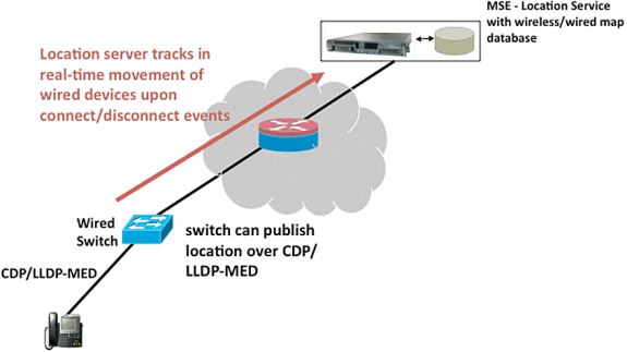
Make sure that you follow the steps to view the wired location.
These are the configuration steps on the switch side:
-
Understand the Slot/Module/Port configuration (1/0/20).
-
Use the correct IOS version that pertains to the respective switch model: IOS 12.2 (50)SE for Catalyst 3K switches and IOS 12.2(52)SG for Catalyst 4K switches.
-
Enable the NMSP.
-
Enable the IP Device tracking.
-
Configure the SNMP community with read-write access.
-
Configure the Civic/ELIN location identifiers.
-
Assign identifiers to the switch interfaces.
These are the configuration steps on the WCS:
-
Go to Configure >Ethernet Switches.
-
Add Ethernet switches.
-
Add the IP address.
-
Enable Location Capable.
-
Enter the SNMP Community (read-write). The SNMP community string entered must match that value assigned to the Catalyst switch.
-
-
Go to Services > Synchronize Services > Switches.
-
Click Assign to assign it to preferred MSE.
-
Choose the switch and synchronize.
-
-
Go to Services > Mobility Services, and click MSE.
-
Go to System > Status > NMSP Connection status.
-
Check for the active NMSP status for each switch.
-
After you complete the steps on the switch and the WCS, you can view the wired elements on the WCS:
-
Under Context Aware Services, click Wired Switches under Wired.
-
A list of the switches displays.
-
Click Switch IP Address to view details (see Figure 30).
Note: Read-write SNMP access is required in order to add WLCs to the WCS. The WLC will not receive the MSE key-hash with SNMP read-only access mode.
Figure 30: Wired Switches - Switch Information 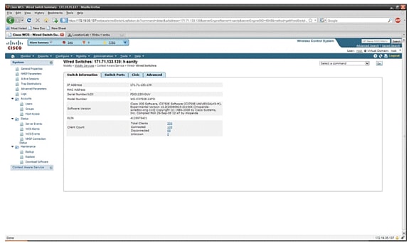
-
You can also view switch ports and Civic information (see Figure 31 through 33) or change the listing order (ascending, descending) of port IP addresses, slot numbers, module number, and port number. Just click the respective column heading.
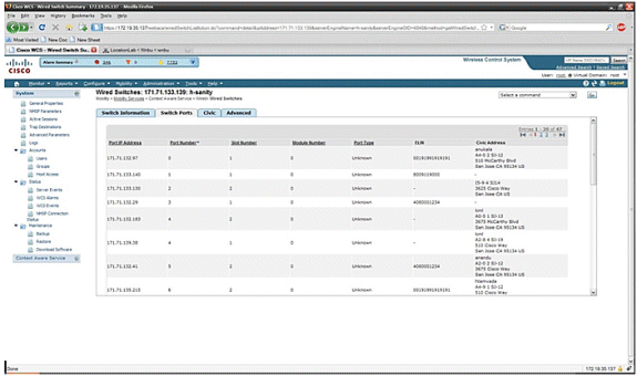
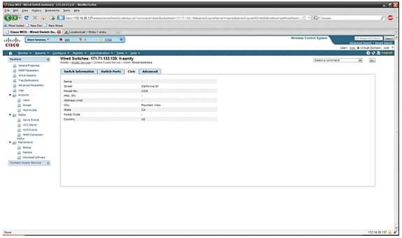
The Advance tab gives additional civic information:
Figure 33: Wired Switches - Advanced Information 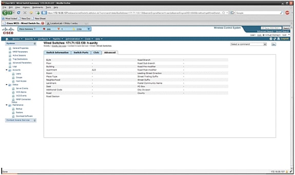
Wired clients that are seen by all switches can be viewed when you click Wired Clients under Wired Context Aware Service > Wired > Wired Clients.
Wired clients can be searched by IP address/partial IP address/Mac Address/ partial Mac Address/802.1x username/VLAN ID as shown in Figure 34.
Figure 34: Wired Clients - Search results 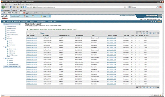
A switch has a specified number of switch ports and clients; hosts are connected at these ports. When you configure the location for a specific switch port, the client connected at that port is assumed to have the port location.
If a switch (switch2) is connected to a port (such as port1) on another switch (switch1), all the clients connected to switch2, are assigned the location that is configured on port1.
You can also view details of the wired clients when you click the respective client to get device information, port associations, civic addresses, etc (see Figures 35 through 38).
Figure 35: Wired Clients - Device Information 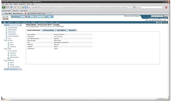
Click the Port Association tab to see the physical location of the switch port/slot/module on which the wired client terminates, the client status (connected, disconnected, or unknown), and the switch IP address:
Figure 36: Wired Clients - Port Association Information 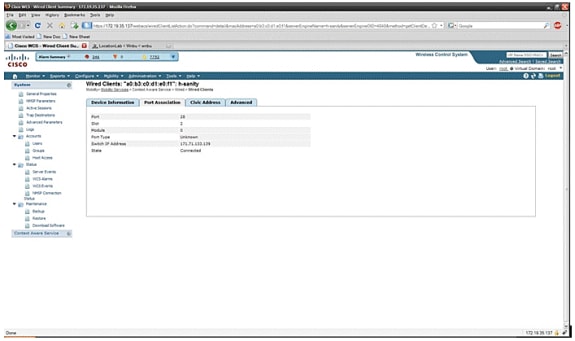
Figure 37: Wired Clients - Civic Address Information
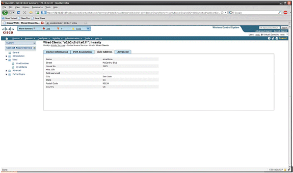
Figure 38: Wired Clients - Advanced Information
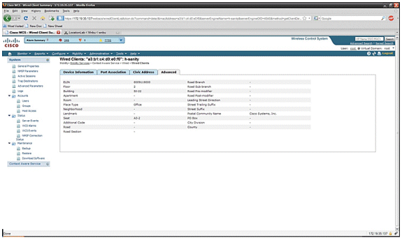
Section 3: Validation and Improvement of Your Context Aware Network
WCS Accuracy Tool
Before the WCS 5.0 release, it was difficult for users to know what accuracy they saw on their wireless network. There was not a standard way to quantify the level of accuracy with the Context Aware deployment. The WCS 5.0 release introduced an integrated accuracy tool. Tag and/or Wi-Fi clients are positioned at reference points on the floor map in WCS. A detailed report is generated by WCS with different levels of accuracy and error distribution over time and space.
There are two forms of accuracy testing:
-
Scheduled accuracy
-
On-demand accuracy
Users can choose either of these methods after they choose the floor on which to run the accuracy test as shown in Figure 39. These tests are run on the same floor.
Figure 39: On Demand Accuracy Test 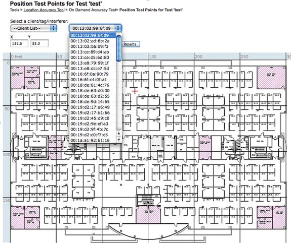
Scheduled Accuracy Test: This test is run on an active environment (live network). Clients and/or tags are prepositioned on the floor, and the test is scheduled through WCS. This test uses the “actual” location of an element versus the “measured” location. User can modify the test:
-
Add/delete the elements
-
Change the positions
-
Change the schedules
The test can be run as a scheduled task and generate alarms if it falls below certain range of accuracy. This type of test must be run periodically since the RF environment in a given deployment can change, which, in turn, impacts the location accuracy.
Figure 40: Accuracy Test Result 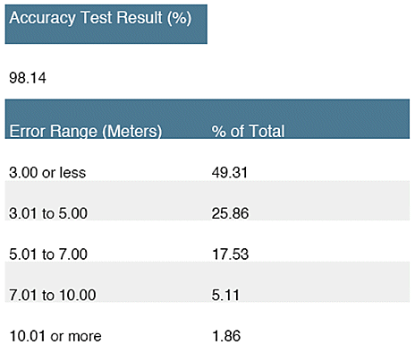
In the example shown in Figure 40, 98.14% represents the number of devices in the test that were detected within 10m, that is, this is the sum of 49.31, 25.86, 17.53 and 5.11.
On Demand Accuracy Test: This test is run when a user does not have any active clients and/or tags deployed in their network and is interested in measuring accuracy. This test can be run when a floor does not have prepositioned tags/clients. This is similar to the accuracy test that was in WCS prior to release 5.0 with single client. The user places a client at a particular location and indicates that location on the floor map in WCS by dragging the test with “drag and drop.” The user clicks Start, waits a few minutes for the RSSI collection process to complete, and clicks the Stop button. The user can then continue the test and move to the next point on the floor map. When all the points have been collected, the user can click the Analyze results button to run the test. This produces the accuracy results in a report format.
These are key points to remember when you run either of the accuracy tests:
-
Client must be seen by a minimum of three APs
-
Accuracy depends on the triangulation and RF fingerprinting
-
Advanced debugging on the MSE must be enabled
-
At a given point on the floor map, wait for about a minute with the client in place, that is, stationary, before you run the accuracy test. This provides the wireless client with sufficient time to update the MSE with its location. Run the test for two minutes.
Location Readiness Tool
WCS provides a tool - the Inspect Location Readiness feature - that allows a network designer to perform a quick predictive check of the location performance for a floor before the cable is pulled, equipment is deployed, or calibrations are performed.
This tool is a distance-based predictive tool and assumes a typical office type building. Consequently, some degree of variance occurs between predicted and actual results. Cisco recommends that the location readiness tool be used in conjunction with other best-practice techniques.
Inspect Location Readiness takes into consideration the placement of each access point along with the inter-access point spacing indicated on floor maps to predict whether the estimated location tracking accuracy will be within 10 meters in 90 percent of all cases. The output of the location readiness inspection is green and red graphical representation of the areas that are predicted to produce this level of accuracy and problem areas, respectively.
The Location Readiness Tool assumes that access points and controllers are known to WCS and have been defined on the WCS floor maps. While it is not necessary to actually install access points and antennas on walls and ceilings in order to conduct a location readiness assessment, all applicable controllers must be added to WCS along with their registered access points with the icons that represent the access points placed on the appropriate floor maps. Once the access points that are to be placed on floor maps have been added to the WCS database, subsequent location readiness assessments can be conducted with these same access points, even if they are not reachable from WCS at that time. Because the location readiness inspection is based on access point placement and the inter-access point distances shown on the floor maps, accurate map placement of access points is critical when you use this tool. The location readiness tool is used only to assess the preparedness of the design to perform RF Fingerprinting-based location tracking. It does not validate any aspect of the design to perform chokepoint location, especially with regard to the definition or positioning of chokepoint triggers. After access point placement has been performed, choose the floor map of which you wish to verify the location readiness and then choose Inspect Location Readiness from the upper right-hand drop-down command menu.
A point is defined as "location-ready" if these are all determined to be true:
-
At least four access points are deployed on the floor
-
At least one access point is found to be resident in each quadrant that surrounds the point-in-question
-
At least one access point resides in each of at least three surrounding quadrants located within 70 feet of the point in question
Figure 41 illustrates these three location readiness rules.
Figure 41: Location Ready Point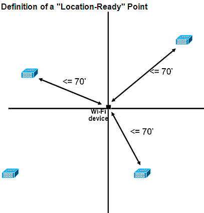
The WCS screen capture shows an example of a floor deployment where not all areas have passed three-point location readiness assessment described earlier for 10m/90% accuracy. Although there are green areas toward the center of the figure, notice that red areas abound as you get beyond the perimeter access points that represent the convex hull. With a solid understanding of the requirements that define location readiness, the information contained in this figure can be used to help determine how many APs need to be relocated or added to improve performance. For example, if a 10m/90% or better location accuracy is required within the red areas, additional access points can be introduced to establish a more clearly delineated floor perimeter, which includes the placement of access points in the corners of the floor and re-checks inter-access point distances. When you implement these types of modifications, the ability of the Cisco UWN to resolve the location of tracked devices in these highlighted areas is likely to be significantly enhanced.
Figure 42: Example of Location Readiness Tool Usage 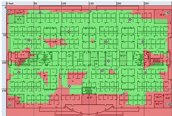
The location quality can be verified for a wireless deployment based on the ability to meet the location specification (10 m, 90%), based on data points gathered within a physical inspection and calibration as shown in Figure 42. When you use the Location Readiness Tool, a color-coded map appears that shows areas that meet (green=yes) and do not meet (red=no) the 10 meter, 90% location specification.
Figure 43: Inspect Location Quality Tool 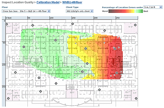
After you perform a calibration on a specific area or map, this data can be reviewed to verify the raw data collected during calibration as shown in Figure 43. It is important to verify the raw data at each data collection point with respect to the physical measurement and associated AP RSSI value. Anomalies in the AP positioning, antenna, or even measurement reference points can easily be identified and corrected before they are applied to the maps. Additional information on the perceived accuracy level and contributing APs can also help to assess the overall location accuracy.
Context Aware – System Performance
In a deployed Context Aware solution, multiple tags and/or clients can move simultaneously. The greater the number of devices that move, the greater the processing load on the MSE. This, in turn, affects the overall latency of the network. Latency in this context refers to the delay between when the MSE receives RSSI information about a device and when its location is calculated by the MSE. These are the maximum number of elements that move at any given instant:
-
100 elements moving/second for MSE-3310
-
650 elements moving/second for MSE-3350
End-to-end latency of the system:
-
Clients and tags: ten seconds under a full load with 650 elements moving/second (starts with WLC software release 5.1)
Latency is also related to the NMSP aggregation window, which can be tuned. See the RFID Tag and WLC Configuration/Tuning section in the subsection entitled “How Much Time Between Iterations?”
-
Maximum number of application sessions: 1024
-
Maximum number of destinations of northbound API: 1024
-
Maximum number of coverage areas: 50/floor
-
Coverage area size cannot be less than typical location accuracy (10m). Typical coverage size is a minimum of 50 feet by 50 feet(2,500 square feet).
-
• Number of APs per floor:
MSE/2710 has no limitations as such. The main restriction is due to the recommendation of having less than 100 AP’s as per WCS recommendations - otherwise WCS maps become unmanageable, provides poor resolution and very slowly builds map details. There is also a limit on how many tracked devices can be viewed on a WCS map.
• Number of Controllers per MSE:
Same controller can be synchronized with more than one MSE with a few exceptions:
-
If controller is on 4.2 or 5.0 code, then multiple NMSP connections are not supported, so they need not be synced to more than one MSE.
-
WLC with wIPS AP cannot establish NMSP connection with more than MSE. This is because of the fact that wIPS AP can only talk to one MSE running wIPS adaptive services.
One WLC can have up to 10 NMSP connections.
One MSE supports up to 500 NMSP connections. But it is important to understand this from CAS deployment perspective. Each WLC is capable of tracking several clients (5000 clients per WLC4400). So in pragmatic deployments with very few controllers MSE CAS reaches its tracking limit upto 18000 devices. There are two glass ceilings which one should keep in mind, one is 5000 clients per controller and other is 18000 devices per MSE 3350. If we hit any of these limits than we maximize the capacity of the system.
There is always a limit on doing scalability testing, and we have performed stress tests with 100 controllers per MSE running location traffic.
• Number of MSEs per WCS:
Although MSE can be managed by single WCS, but WCS can manage multiple MSEs. WCS has bounds from several perspectives, which could determine how many MSEs it could manage based on distribution of those units across MSEs. So the factors such as Maximum number of elements supported, Maximum number of floors supported, or Maximum number of APs supported come into play. Officially we support 5 MSEs per WCS.
• Number of Network Designs:
There are no limits for Network Designs added to MSE. However Aeroscout engine has a limit depending on the number of floors, dimensions and amount of elements for MSE.The maximum number of floors is limited to 255. And assuming devices deployed every 60m and grid resolution of 1m, small installation can support 15 maps and large installation (higher memory requirement) can support 90 maps.
Northbound Notifications
The MSE can forward all known tag data to a northbound SOAP listener. If configured, each time a tag notification frame is reported to the MSE or each time the MSE calculates location for a tag, it can notify the listener. This is useful if third-party applications wish to receive instant updates each time a tag is heard, rather than query it periodically. This can be configured through the Notification Parameters UI: Services > Mobility Services > Context Aware Service > Advanced > Notification Parameters.
In order to support Northbound Notifications, follow these recommendations:
-
Regular tag beacons cannot be less than three to five minutes apart.
-
The tag notification frame interval to move tags must be between one and ten seconds.
-
The queue limit on notification parameters must be set to greater than the number of tags supported.
-
Ensure that the SOAP listener does not go down.
-
Ensure that the SOAP listener returns a valid empty SOAP envelope in response to the notification.
-
Ensure that the SOAP listener processes the inbound notifications speedily.
If these conditions are not met, the notification queue of the MSE can overflow. This condition is visible in the Notification Parameters page as the "Notifications Dropped" counter (see Figure 44).
Figure 44: Northbound Notifications 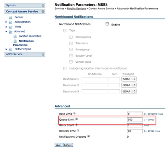
This entire section is only valid if the northbound listener is not able to deal with the traffic of northbound notifications and wants to suppress them unless the tag has something important (or of interest) to report:
Filter northbound notifications based on tag payloads of interest to make the system more scalable. For example, if a tag beacons every few seconds, but the tag payload contains only battery information or movement telemetry that is not of interest, the generation of northbound events on the receipt of these tag payloads can be suppressed.
Northbound event filtering is controlled by six new parameters in the aes-config.xml file:
<entry key="send-event-on-location-calc">true</entry>
<entry key="send-event-on-every-beacon">true</entry>
<entry key="send-event-on-vendor">true</entry>
<entry key="send-event-on-emergency">true</entry>
<entry key="send-event-on-chokepoint">true</entry>
<entry key="send-event-on-telemetry">true</entry>
In order to receive ALL notifications, turn on the send-event-on-location-calc and send-event-on-every-beacon. If every single tag payload is not of importance, set selectively. For example, to have the MSE send out notifications only for a location calculation, a call button press, or a chokepoint encounter, turn it on. (Set to "true" in the file. DO NOT DELETE THESE VALUES!):
send-event-on-location-calc
send-event-on-emergency
send-event-on-chokepoint
Turn off the other three flags.
After install/upgrade, ssh into MSE and issue the following commands :
rm /opt/mse/locserver/conf/aes-config.xml 		(won’t exist for new install)
/etc/init.d/msed start 				(creates the aes-config.xml)
/etc/init.d/msed stop
vi /opt/mse/locserver/conf/aes-config.xml
Change filters to match your requirements. Save the file and exit. Restart the msed process.
/etc/init.d/msed start
For further details on the notification, refer to the API document.
RFID Tag and WLC Configuration/Tuning
An RFID tag is a Wi-Fi device equipped with a transmitter and an antenna. It does not associate to access points, so it does not behave like other wireless clients. An RFID tag transmits information on a periodic basis – referred to as tag notification frames, which are multicast packets sent at low data rates. Every x seconds, the RFID tag sends y tag notification frame on its configured channels. It is recommended that tag notification frames be transmitted with a signal strength of 17 dBm. When it completes a cycle across all configured channels, the RFID tag sits in standby and waits for the next transmit period to transmit tag notification frames.
When you deploy RFID for asset tracking in Wi-Fi, this needs to be configured:
1. How many tag notification frames per channel will the RFID tag transmit?
Due to the nature of multicast traffic on 802.11 networks, it is generally good practice to increase the number of tag notification frames per channel.
In a clean RF environment, APs receive tag updates and report them to their WLC, even if the tag is configured to send one tag notification frame per channel. In real life deployments, there is a high probability that a tag update is missed on a given AP due to RF noise or other activity. Missing a tag update on a nearby AP can lead to incorrect location calculations. Repeat the number of tag notification frames per channel to two or three, instead of the default one, to reduce the possibility of the tag update not to be heard by nearby APs.
Consideration for tag battery life is also an important aspect of accuracy and tag notification frame interval and often a compromise must made. Best practice recommendations to track moving object is the use of motion detection tags. Configure a tag notification frame interval, that is, 3 to 5 minutes when stationary, and have an increased frame interval of 1 or 2 seconds when in motion to yield good accuracy and provide long battery life. Configuration and recommendation for best practices can be obtained from the tag manufacture
Refer to AeroScout Documentation.
Another way to compensate a tag update loss on a certain Access Point is to increase the RFID RSSI expiry value on the WLC. The recommended value must be three times the interval period + 5 seconds. With this value, the last RSSI on the WLC is preserved if an AP does not detect the last iteration from a given tag. New updates are pushed to the MSE together with retained data from previous iterations.
One drawback behind this approach is that it can affect accuracy. If motion transmission is not enabled on an RFID tag and the tag moves out quickly from the last location on which it transmitted a tag notification frame, the location calculation is based on the old data. The recommendation is to enable Motion Probing to always base location calculation on fresh AP data and keep the WLC timers as low as possible to reduce latency.
Note: WLC code 5.x provides a new command that also has an effect on the data retained on the WLC. This expiry timer is individually configurable for RFID tags, clients, and rogues. The default expiry setting is five seconds, which prunes stale data from the controller older than five seconds. The RFID timeout setting controls the total time an RFID tag is retained on the controller after it has gone out of range or stops transmission. The combination of these timers together with complimentary settings on the MSE can provide optimal accuracy with minimal NMSP updates between the controllers and MSEs.
The RFID RSSI expiry can be configured with the WLC CLI:
(Cisco Controller) >config location expiry tags ?

<seconds>      Time in seconds
This is command to see if an AP detect is a given RFID tag:
(Cisco Controller) >show location ap-detect rfid ?

<AP name>      Display information for AP name
2. Which channels?
In 2.4 GHz deployment, channels 1, 6, and 11 are the non-overlapping channels in the spectrum. The recommended channels to be configured on an RFID tag are 1,6, and 11. Note that in some scenarios, an AP is able to hear RFID tag updates on a channel that is different from the one on which it operates. By design, the AP drops these updates and does not forward them to the WLC.
3. How much time between iterations?
Configuration of the tag notification frame interval plays an important role for location tracking since it defines the time separation between location calculations or updates. As stated earlier, the tag notification frame interval must be configured for optimal battery life and location accuracy, that is, 3-5 minutes for stationary tags.
Keep in mind that, when a tag moves, more real time information is required to calculate location. When it tracks moving tags, motion transmission must be enabled on the RFID tag with a tag notification frame interval <10 seconds.
4. How much time does an RFID wait between frame transmissions?
When transmitting frames or beaconing, an Aeroscount RFID tag waits for a preconfigured amount of time between its transmissions. This waiting time can be of 128, 256 or 512 milliseconds and is known as “Message Repetition Interval". If 512 msec is configured and the tag is sending one beacon per channel, then the RFID tag finishes a complete iteration within approximately 1.5 seconds. If two frames are sent per channel with the same “Message Repetition Interval", then the tag finishes a complete iteration within 3 seconds.
The RFID tag transmits the configured amount of frames on a specific channel and then moves to the next channel to do the same routine. The time that separates each frame transmission is known as “Message Repetition Interval".
It is crucial for the WLC to receive tag updates from all contributing APs on channels 1,6, and 11 before it sends this data through NMSP to the MSE. The WLC waits for a configurable amount of time, called the Aggregation Window, before it sends the nearby AP list for an RFID tag to the MSE.
Starting with WLC 5.1 software, the NMSP Aggregation Window is configurable and is set to two seconds by default. On releases prior to 5.1, the Aggregation Window on WLC is eight seconds and is not configurable. If a controller receives the same packet from multiple APs in the same aggregation window, it drops the duplicates. If it receives some packets in one window and the remainder in the next, it sends one duplicate packet (the first in the second window) but drops the rest of the duplicates.
It is important to configure the correct Aggregation Window size in order to ensure that the WLC has received updates from all the APs. This window needs to be greater than the amount of time an RFID tag spends to complete a cycle. The common practice is to add at least one extra second to be sure the WLC waits long enough. Configuration of a low Aggregation Window leads to wrong location calculation.
CCA (Clear Channel Assessment) can add additional time for an RFID tag to complete all three channels updates. Most RFID tags do carrier sensing before they transmit. If the wireless medium is busy, they back off for additional time and refrain from transmission. After a predefined time, if the medium is clear they transmit and move to the next channel. If the medium is still busy, the tag suspends transmission for that channel iteration and move to the next channel. The maximum amount of time for the back off is not fixed and can vary from vendor to vendor.
Note: When you use WLC 4.x or WLC 5.x software releases in conjunction with the MSE, the NMSP aggregation window on the MSE is set to 8 seconds.
WCS and MSE Configuration and Tuning
There are number of important configuration parameters which can be configured in WCS and MSE that can affect Location tracking (see Figure 45).
Figure 45: Location Parameters 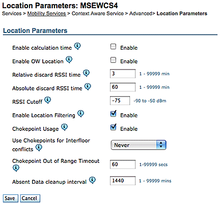
The RSSI Cutoff is an important field that can be tuned for a particular environment. This field specifies the minimum RSSI value below which the MSE ignores when it calculates the location for a given element. This value is only applicable to track clients, that is, it does not apply to tag tracking.
If you specify a very high RSSI Cutoff, such as -60 or -50 with low AP density, it leads to poor location calculation since the MSE excludes RSSI values of reliable hearing APs from its calculation.
If you use a low RSSI Cutoff, such as -85 of -90 and operate in an open space area or with low walls, inter-floor attenuation areas lead to poor location calculation because the MSE includes RSSI values from outlying APs in its calculation.
Although the RSSI Cutoff is a fixed value, the algorithm compensates for missing values when it supplements lower RSSI values from the last iteration or takes values from relative discard repository. Ideally, the optimal RSSI Cutoff value allows for more than five contributing APs with RSSI values higher than -75dBm from the same floor. Buildings that have non-characteristic RF loss can require adjustment of this parameter, but it is normally an indication of a suboptimal deployment.
Jitter: Before the 5.2 release, MSE used to have Location Smoothening mechanism to track clients. Moving average was taken for clients, or, in other words, client movement was averaged. Starting with 5.2 software release, this whole mechanism has been replaced with “Location Filters.” Location Filtering is applied internally on a per client basis. MSE keeps track of which client moves and which is stationary, and it applies filtering accordingly. This reduces the overall jitter of the system. Location filtering is enabled by default. See Figure 46.
Figure 46: Location Filtering 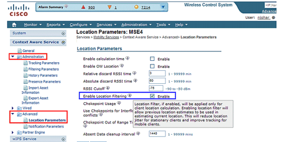
WCS/MSE Communication: This is the deployment recommendation to configure the communication between WCS and MSE:
-
MSE: HTTPS is always enabled (by default). HTTP is disabled by default. Enabling HTTP requires manual configuration through the console access (direct or ssh) into the MSE.
-
WCS: By default, WCS uses HTTPS to communicate with MSE. HTTP can be enabled through WCS GUI.
In certain cases, WCS is not able to communicate with MSE over HTTPS. In this case, adding MSE to WCS or Save on MSE General Properties page keeps reporting the error “HTTPS connection to server failed.” MSE must be pingable (reachable) from WCS, and the ‘getserverinfo’ command on MSE provides status information. It is advised that you enable HTTP on MSE and make WCS communicate with MSE through HTTP.
On MSE, HTTP support is available in releases 5.1, 5.2 and 6.0.
Enable HTTP on MSE that runs version 6.0 software release: Log onto MSE through ssh/console. Issue this command:
root@mse ~]# enablehttp
Enable HTTP on MSE that runs version 5.x software release: Log onto MSE through ssh/console. Issue this command:
[root@mse ~]# getdatabaseparams
<DB PASSWORD>
This command returns the db password. Use this password in this command:
[root@ mse ~]# /opt/mse/locserver/bin/tools/solid/solsql "tcp 2315" dba <DB PASSWORD>
Solid SQL Editor (teletype) v.06.00.1049
Copyright ©) Solid Information Technology Ltd 1993-2008
Connected to 'tcp 2315'.
Execute SQL statements terminated by a semicolon.
Exit by giving command: exit;

update AESSERVERINFO set USEHTTP=1;
Command completed successfully, 1 rows affected.

commit work;
Command completed successfully, 0 rows affected.
Press Control-C to exit the database shell. Perform MSE platform restart with /etc/init.d/msed stop; /etc/init.d/msed start.
Enable HTTP communication from WCS (runs software release 6.x) to MSE:
-
Make sure HTTP is enabled on MSE with the previous steps.
-
In WCS, choose HTTP on the MSE General Properties page. This enables HTTP communication between WCS and MSE. See Figure 47.
Now WCS starts to communicate with MSE over HTTP.
Note: In order to enable HTTP on WCS 5.2, refer to the WCS 5.2 Configuration Guide.
Figure 47: Enabling HTTP communication between MSE and WCS 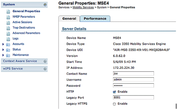
MSE Licensing
MSE licenses are required to retrieve contextual information on tags and clients from access points from 6.0 code onwards. The license of the client includes tracking of wireless/wired clients, rogue clients, and rogue access points. Licenses for tags and clients are offered independently. Licenses for tags and clients are offered in a range of quantities, which range from 1,000, 3,000, 6,000, and 12,000 devices. Cisco offers licenses for clients and tags. The actual creation of licenses and management of SKU related information is handled by FlexLM license system developed and maintained by the SWIFT team.
WCS is the management system used to install client and wIPS licenses on MSE. Licenses for tags have to be activated through AeroScout and installed on the MSE with the AeroScout Systems Manager.
For detailed information on MSE licensing, refer to Cisco 3300 Series Mobility Services Engine Licensing and Ordering Guide.
New Purchases
Clients
-
Customer purchases SW license and receives Product Authorization Key (PAK) by mail (license document).
-
Customer registers PAK for clients on https://tools.cisco.com/SWIFT/Licensing/PrivateRegistrationServlet (registered customers only) .
-
Enter MSE UDI information in the “host ID” field. Accept the agreement and continue. License is sent to customer through email.
-
MSE UDI can be obtained on the WCS through these tabs:
-
Services > Mobility Services > MSE > System > General Properties
-
-
Without a license, the MSE provides “try before you buy” functionality for 60 days (Evaluation License).
-
Evaluation license is usage-based and good for 60 days; it can be extended only once.
-
Evaluation license limits:
-
Clients: 100
-
Tags: 100
-
wIPS APs: 20
-
-
Evaluation license is always enforced, but if the platform limit has been reached based on installed license(s), the evaluation license of separate service can still be used. For example, if a customer has an MSE-3350 and has installed licenses to track 18K devices (clients and/or tags), and 18K devices are actively tracked, they can still use an evaluation license for wIPS, even though the platform limit is exceeded.
-
Evaluation License timer starts from the day it is generated, so the Evaluation License extension needs to be installed immediately.
-
Once the License is installed, it is usage based dependent upon the service is enabled/disabled.
-
If the Evaluation License expires, and the MSE is not restarted, core MSE services continue to run, and licensed services, such as Context Aware, also continue to run, but devices are not tracked.
-
If the Evaluation License expires, and the MSE is restarted, the licensed services does not start. Devices are not tracked.
If you do not have PAK
-
Go to the Sales Order Status Tool at http://tools.cisco.com/qtc/status/tool/action/LoadOrderQueryScreen.
-
From the Type of Query drop-down list, choose Sales Order from.
-
Enter the Sales Order Number in the Value field.
-
Display with Check Show Serial Number and click Search.
-
The window with the MSE order detailed information displays.
-
In the Order detailed window from the table, click expand Line 1.1.
-
Under the Product column, second line, copy the PAK number (starts with 3201J) that you want to register in order to obtain the license.
-
To register PAK, go to https://tools.cisco.com/SWIFT/Licensing/PrivateRegistrationServlet (registered customers only) .
-
Click the Product License registration link from the left, enter the PAK number in the blank field, and submit.
-
Enter the MSE UDI information in the Host ID field. Accept the agreement and continue.
-
A license is generated, and an email is sent to your email ID.
Tags
-
The customer purchases the software license and receives the PAK (Product Authorization Key) by mail (license document).
-
The customer registers the PAK for tags at http://support.AeroScout.com
. -
If you do not have an account, create a new account with the “Create New Account” link.
-
Once the account has been created you receive a notification email that contains your username and password.
-
Log on to the AeroScout Support Portal
. -
Under the Home tab, click the “Register Products Purchased from Cisco” link.
-
Register your products and provide contact details, PAK#, MSE ID (MSE S\N), and the Installation Type. You receive an email message that confirms the registration.
-
The SE Serial number can be obtained from the WCS tabs:
Services > Mobility Services > MSE > Advance Parameters
-
AeroScout verifies your PAK number within two business days. Upon verification, a notification that contains your license key, instructions how to download Context Aware Engine SW, and relevant user guides are sent to your email address. If your PAK number is found to be invalid, you are requested to register a valid PAK number again.
Upgrade – Client License
-
The customer purchases the new license and receives PAK with mail.
-
The customer receives the PAK and obtains license key through email.
-
The customer installs the license key on MSE.
-
Adding evaluation license count (when existing/installed client license count equals MSE max.): WCS allows the evaluation license to be added even though the maximum device (client) count of MSE has been reached. For example, if the customer has MSE-3350, has 18K client license installed, and wants to add tag tracking and/or wIPS, WCS can add an evaluation license for either or both services.
Upgrade – Tag License
-
Adding tag license count (when existing/installed tag license count is less than MSE maximum): The existing tag license is overwritten by a new license, for example, if a customer has an existing license to track 1K tags and wants to upgrade to track 4K tags, they purchase a 3K license to add to their existing 1K license. AeroScout issues a 4K tag license to cover the entire new tag count.
-
Adding tag license count (when existing/installed tag license count equals MSE max.): The AeroScout System Manager returns an error message. The existing tag license remains in place. For example, customer has MSE-3350 and has an 18K tag license installed on MSE. If they attempt to install a 3K tag license, AeroScout System Manager gives an error message. The tag license needs to be manually deleted from MSE since the AeroScout System Manager does not have the ability to delete tag licenses. In order to delete the new tag license, the customer needs to uninstall the MSE image, remove the database option, and reinstall the MSE software.
-
Adding evaluation license count (when existing/installed tag license count equals MSE maximum): WCS allows an evaluation license to be added even though the maximum device (tag) count of MSE has been reached. For example, if the customer has MSE-3350, has an 18K tag license installed, and wants to add client tracking and/or wIPS, it can add an evaluation license for either or both services.
Existing Customers (applies only when upgrading to 6.0 software release)
-
Visit https://tools.cisco.com/SWIFT/Licensing/PrivateRegistrationServlet (registered customers only) to register PAK for clients and get license key as explained above in New Purchases section. If PAK has been misplaced, then customer needs to call Cisco TAC/GLO.
-
Install license file on MSE through WCS.
-
License is tied to MSE UID.
-
Made up of platform (MSE 3310 or 3350) and unique serial number. Example UDI: AIR-MSE-3310-K9:V01:QCN1224001Y. In this example, the serial number is QCN1224001Y.
-
The MSE License is tied to the Unique Device Identifier (UDI). If the same unit is fixable, the UDI is the same, and the same License can be rehosted, but, if the unit has to be replaced, the UDI changes, so a new license has to be generated. MSE does not accept the license if UDI does not match. Customers can call Cisco TAC and provide the old and new UDI. Cisco TAC deactivates the old license and issues a new one.
-
The MSE-3350 can track up to 18,000 devices (any combination of clients and tags) with the proper license purchase. Updates on the locations of elements tracked are provided to the mobility services engine from the Cisco wireless LAN controller.
-
Only those elements designated for tracking by the controller are viewable in Cisco WCS maps, queries, and reports. No events or alarms are collected for non-tracked elements, and none are used to calculate the 18,000-element limit for clients or tags.
After successful installation of License, the license type now shows as “Permanent” as shown in Figure 48.
Figure 48: License Center 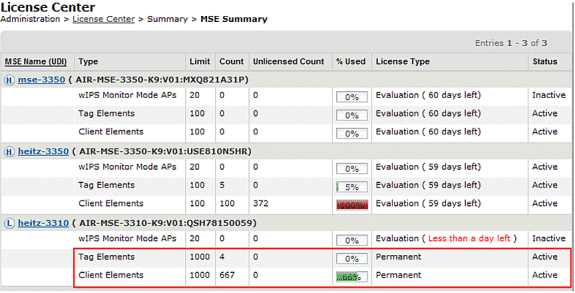
Note: When a client or tag is inactive for 24 hours, they no longer count against their respective license count.
The licensing file is stored at “opt/mse/licensing”.
When you upgrade from MSE 5.x to 6.x, ensure that these steps are followed in sequence:
-
With WCS, perform a MSE database backup of MSE 5.x, that is, the currently running MSE system.
-
In order to back up data and configuration for Tags, refer to the Context-Aware Service Software Configuration Guide.
-
Upgrade MSE to 6.x software. The alert messages display within the upgrade process on the MSE about “Licensing” at installation.
-
Install the MSE license through WCS. A warning message shows if a license greater than the MSE system capacity is installed and the license installation process is blocked. For example, if a customer has an MSE-3310 and attempts to install a 6K client license, a warning message displays since an MSE-3310 can track a maximum of 2K devices.
-
Restore the MSE database with WCS.
-
In order to restore data and configuration for the Tag engine, follow AeroScout Documentation
. -
For details on these steps, refer to Appendix B of this document and the Context Aware Configuration Guide for Release 6.x.
Note: With software release 6.0 for tag tracking, AeroScout engine configurations and license data are preserved within WCS/MSE backup and restore processes. Any configuration performed on MSE that runs software version prior to 6.0 is not preserved automatically. Upgrading from 6.0 to 6.x, this configuration data is maintained when you use the MSE backup/restore procedure as outlined in Cisco documentation. If a customer upgrades from 5.2 to 6.0, they need to follow the manual procedure as per AeroScout Documentation
. Caution: The number of supported clients, tags, and access points (wIPS) is reset to 100 clients, 100 tags, and 20 APs when you upgrade to release 6.x in the absence of the appropriate license. All but 100 elements are marked inactive. The historical data for all elements that were tracked remains in the database and can be queried within the location API on the MSE. These limits correspond to 60-day evaluation licenses that are provided by default on non-licensed MSE.
Modify these tracking parameters with Cisco WCS (see Figure 49):
-
Enable and disable element locations (wired/wireless clients, active asset tags, and rogue clients and access points) that you actively track.
-
Set limits on how many of a specific element you want to track.
-
For example, given a client license of 12,000 trackable devices (wired/wireless), you can set a limit to track only 8,000 client stations (which leaves 4,000 devices available to track rogue clients and rogue access points). Once the tracking limit is met for a given element, the number of elements not tracked is summarized on the Tracking Parameters page.
-
Disable tracking and reporting of ad hoc rogue clients and access points.
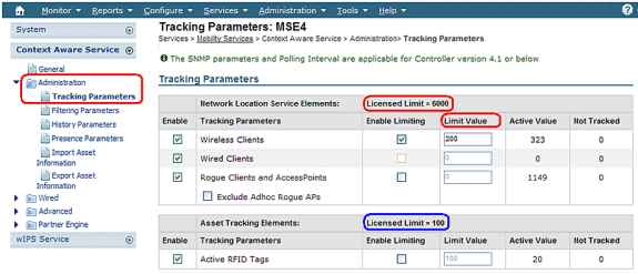
The actual number of tracked clients is determined by the license purchased.
Active Value (see Figure 49): Indicates the number of client stations currently being tracked.
Not Tracked (see Figure 49): Indicates the number of client stations beyond the limit.
Excess elements (tags/clients/rogues) will not be tracked as shown in Figure 50.
Figure 50: License Usage 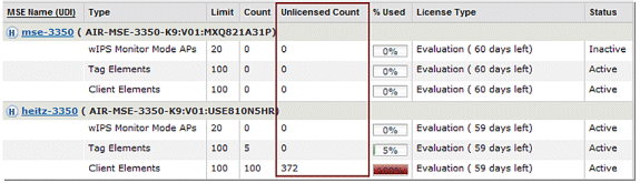
How Multiple Service Are Scaled
The MSE with the 6.0 sw release supports the simultaneous operation of Context-Aware and WIPS. Feature co-existence limits are enforced. Over the limit combinations will be non-TAC supported, and are not even possible as license cannot be added that will cause MSE capacity to be exceeded.
The supported combinations are shown in Figures 51 and 52.
Figure 51: MSE-3350 System Capacity : wIPS Monitor Mode APs & Context-Aware Devices 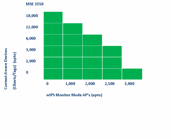
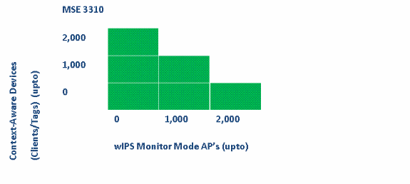
Some examples:
-
Customer is interested in tracking 6K devices using the Context-Aware service, then he/she has capacity to have up to 2,000 wIPS Monitor Mode APs on the MSE 3350
-
Customer is interested in tracking 3K devices using the Context-Aware service, then he/she has capacity to have up to 2,500 wIPS Monitor Mode APs on the MSE 3350
-
Customer is interested in tracking 1K devices using the Context-Aware service, then he/she has capacity to have up to 1,000 wIPS Monitor Mode APs on the MSE 3310 and a capacity to have 2,500 wIPS Monitor Mode APs on the MSE 3350
Troubleshooting
MSE is Unreachable
If MSE is detected as unreachable from the WCS perspective, possible reasons can be these:
-
The API login credentials in WCS are configured incorrectly. The appliance has two sets of credentials: one is for the appliance shell interface and another for the API credentials. WCS needs the API credentials when it adds MSE. Refer to Appendix A of this document.
-
Route and Firewall connectivity rules block connectivity between WCS and MSE. Refer to the “Verify Network Connectivity” section in this document.
-
The WCS Background task “Mobility Service Status” has been disabled. Enable it in WCS through Administration > Background Tasks > Other Background Tasks > Mobility Service Status .
-
The MSE Service Context Aware is enabled and up from the MSE CLI.
-
In rare situations, HTTPS can have a connectivity issue. You can enable the HTTP option under MSE General Properties in WCS. Refer to the “WCS/MSE Communication” section of this document for details.
-
MSE has crashed. On MSE, CLI “getserverinfo” cannot return an output. Collect all logs under/opt/mse/logs directory and contact Cisco TAC.
No Elements are Located
If no elements are located in MSE, possible reasons can be these:
-
MSE is unreachable.
-
The evaluation license has expired.
-
MSE is reachable and license applied, but the MSE Context Aware Module Service is not enabled.
-
Tracking for clients and/or tags is not enabled on the MSE Tracking Parameters page. Refer to the “MSE Licensing” section of this document for details.
-
Network designs and/or controllers have not been synchronized with MSE.
-
Access points were not positioned on WCS Maps.
-
NMSP connections are not established between MSE and Controller(s). Refer to “Verify NMSP Connection Between WLC and MSE” section of this document for details.
-
Access points in WCS have non-Cisco antennas (type chosen was “Other”). In this case, access points in WCS must be set to another similarly supported antenna type and resynchronized network design with MSE.
-
Wireless LAN controller (WLC) does not detect clients. Troubleshoot on WLC with CLI “show client summary”.
-
Wireless LAN controller (WLC) does not detect active RFID tags. Troubleshoot on WLC with CLI “show rfid summary”.
Tags are not Located
When Tags are not located (but other clients are), there can be a problem within the AeroScout Engine; possible reasons are these:
-
Active RFID tags are not being tracked by the WLC. This command must be present in the WLC configuration: config rfid status enable.
-
Wireless LAN controller (WLC) does not detect active RFID tags. Troubleshoot on WLC with CLI “show rfid summary.”
-
Tags are seen by WLC but not seen in WCS. Verify that NMSP notification are sent to MSE with this command: debug rfid nmsp enable.
-
The AeroScout Engine not installed in MSE. In releases 5.1 and 5.2 the engine must be installed separately. From releases 6.0 onwards the engine is bundled with MSE.
-
The license is not installed for the AeroScout Engine.
-
The AeroScout Engine does not register with MSE. Check the Partner Engine status page in WCS.
-
MSE contains too many maps, or the maps are too large. Refer to the AeroScout engine guidelines.
-
After an upgrade, configuration can need to be restored to the AeroScout engine.
-
The floor map does not have an image (resolved in recent releases).
-
MSE tracks only CCX-compatible tags, and the deployment has only unsupported non-CCX tags, or they have not been configured to transmit in CCX format.
Certain Elements are not Located (Clients or Tags)
If MSE tracks certain elements, but others are not visible, possible reasons can be these:
-
MSE runs on an Evaluation License, limited to 100 elements.
-
MSE runs with a valid License, but the capacity has been exceeded, so any extra elements (Clients/Tags/Rogues) are discarded.
-
Certain controllers do not have NMSP connectivity with MSE.
-
The element has disappeared from the network and no longer transmits. MSE stores the element in its history record, but it disappears from WCS screens.
-
Filtering Options have been applied in WCS Maps layers preventing some elements to be displayed.
-
MAC Filtering options are enabled in MSE Filtering Parameters, discarding some elements.
-
MSE tracks only CCX-compatible tags; the deployment has a combination of CCX and non-CCX tags.
-
Client/tag troubleshooting extension for location:
-
Check whether WCS sees this client or not? Through SNMP, this functionality already exists for clients. (Client troubleshooting). This needs to be extended for tags.
-
Look for the client in the location assigned controllers. Use WLC command show client summary.
-
Determine how long ago WLC saw the client use the WLC command show client <MAC address> detail.
-
Determine when APs last saw the client with the WLC command show client <MAC address> detail.
-
WLC not Connected with MSE
When a Controller does not establish connectivity with MSE, possible causes are these:
-
Controller is not reachable from MSE or WCS perspectives.
-
The WCS had temporary connectivity issue with the controller and was unable to push the hash security key for NSMP connection. Verify the SNMP connectivity between WCS and Controller.
-
The controller and MSE do not have a correct NTP configuration or their time difference is significant. Configure times correctly.
-
Controllers older than 4.2 release do not support NMSP.
-
Controllers prior to release 5.1 release do not support multiple MSE connections.
-
If a controller is assigned to an MSE with wIPS enabled, the same controller cannot be assigned to another MSE simultaneously.
-
WCS does not have read/write access to the WLC when sync is done. This results in the inability of the WCS to push the MSE MAC and key hash to the WLC.
Notifications do not Reach External Partner Applications
In situations where a partner application does not receive notifications from MSE, the possible reasons are these:
-
The connectivity between MSE and the external application is not established. Verify XML/API traffic.
-
The external listener application is down.
-
The external listener is slow to parse the incoming notifications. In this case, MSE waits for external listener to process, which can lead to congestion on MSE outbound queues.
-
The MSE drops notifications due to the relatively small size of its outbound queue compared to the amount of tag notification frames expected in the network. Verify that tags have a reasonable configuration, especially for motion acceleration/de-acceleration. Increase the queue size in the MSE Notification Parameters. Refer to the “Northbound Notification” section in this document.
Wired Location does not Work
If no elements are tracked when you use the wired location, the possible reasons are these:
-
NMSP connectivity issue between MSE and Wired Switches.
-
The wired switch runs an older version that does not support wired location.
-
The wired switch has correct version but NMSP is not enabled. Enable it with the CLI option.
-
The wired switch must have IP Tracking Option enabled to start tracking its connected clients.
-
The wired switch was not added to WCS.
-
Possible problems while you add a wired switch in WCS:
-
Wrong SNMP community strings.
-
Switch OID is not supported in WCS.
-
-
The wired switch was added to WCS but is not synchronized with MSE.
-
The wired switch is available for Synchronization. Verify that the switch was added with the “Location Capable” flag enabled in WCS.
-
The wired switches support only one NMSP connection with a MSE.
-
Wired tracking is not enabled in MSE tracking parameters.
MSE Licensing
-
UDI mismatch message when you install the license – MSE licenses are tied to MSE UDI, so make sure that the license installed is created for the correct MSE. You cannot interchange licenses between different MSEs.
-
License installation is blocked due to element that exceeds the allowed limit on that MSE - check the license capacity for each service on different MSE platforms as outlined under Preface section.
-
Error can display if you try to install or delete two licenses in a row – the reason for this is that every time CAS licenses are installed, all the services restart, and every time the wIPS license is installed, the wIPS service restarts. Before you proceed to install another license right away, make sure that all the services have come up.
-
MSE Licenses are installed under /opt/mse/licenses.
Verify Network Connectivity
Ensure that no firewalls block the connectivity between the MSE, WLC and WCS. If you must firewall off these boxes, create wild card rules so that these machines can talk to each other successfully (see Figure 53).
Figure 53: Verify Network Connectivity 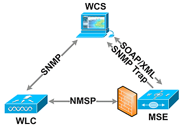
Verify NMSP Connection Between WLC and MSE
(Cisco Controller) >show nmsp status

LocServer IP    TxEchoResp    	RxEchoReq    TxData    RxData
--------------  -----------    	---------   --------   -------
172.20.224.17       18006       	18006        163023      10

(Cisco Controller) >show auth-list

<snip>

Mac Addr                  Cert Type    Key Hash
-----------------------   ----------   ----------------------------------------
00:1e:0b:61:35:60         LBS-SSC      5384ed3cedc68eb9c05d36d98b62b06700c707d9
If the NMSP connection is not established after you add MSE to WCS, one possible reason is clock discrepancy between WLC and MSE. The recommendation is to use an NTP server to synchronize the clocks. If that is not possible, the clocks on the WLC and MSE can be configured manually. The main issue with the system clocks is to ensure that the WLC time is not behind the time that is set on the MSE.
Note: Time synchronization between controllers is essential in large multiple WLC deployments.
If an NMSP session is still not established, the network administrator can manually set up NMSP session by entering the MSE key hash into the WLC.
MSE
root@mse ~]# cmdshell
cmd> show server-auth-info
invoke command: com.aes.server.cli.CmdGetServerAuthInfo
----------------
Server Auth Info
----------------
MAC Address: 00:1e:0b:61:35:60
Key Hash: 5384ed3cedc68eb9c05d36d98b62b06700c707d9
Certificate Type: SSC


WLC
(Cisco controller) >config auth-list add lbs-ssc <MSE Ethernet MAC> <MSE key hash>
Verify MSE is Operational and Receives Tag And Client Info from WLC
The getserverinfo command on the MSE provides this output:
[root@MSEWCS4 ~]# getserverinfo
MSE Platform is up, getting the status

-------------
Server Config
-------------

Product name: Cisco Mobility Service Engine
Version: 6.0.49.0
Hw Version: V01
Hw Product Identifier: AIR-MSE-3350-K9
Hw Serial Number: MXQ828A4L9
Use HTTP: false
Legacy HTTPS: false
Legacy Port: 8001
Log Modules: 262143
Log Level: INFO
Days to keep events: 2
Session timeout in mins: 30
DB backup in days: 2

-------------
Services
-------------

Service Name: Context Aware Service
Service Version: 6.0.35.0
Admin Status: Enabled
Operation Status: Up

Service Name: Wireless Intrusion Protection Service
Service Version: 1.0.1096.0
Admin Status: Enabled
Operation Status: Up

--------------
Server Monitor
--------------

Mon Mar 16 14:43:52 PDT 2009
Server current time: Thu Apr 02 14:55:00 PDT 2009
Server timezone: America/Los_Angeles
Server timezone offset: -28800000
Restarts: 3
Used Memory (bytes): 166925392
Allocated Memory (bytes): 238354432
Max Memory (bytes): 1908932608
DB virtual memory (kbytes): 6694
DB virtual memory limit (bytes): 0
DB disk memory (bytes): 241696768
DB free size (kbytes): 6304

---------------
Active Sessions
---------------

Session ID: 17155
Session User ID: 1
Session IP Address: 172.20.224.30
Session start time: Tue Mar 17 16:50:48 PDT 2009
Session last access time: Thu Apr 02 14:50:30 PDT 2009

-------------
Context Aware Service
-------------

Total Active Elements(Clients, Rogues, Interferers): 2263
Active Clients: 591
Active Tags: 24
Active Rogues: 1648
Active Interferers: 0
Active Wired Clients: 0
Active Elements(Clients, Rogues, Interferers) Limit: 6000
Active Tag Limit: 100
Active Wired Clients Limit: 0
Active Sessions: 1
Clients Not Tracked due to the limiting: 0
Tags Not Tracked due to the limiting: 0
Rogues Not Tracked due to the limiting: 0
Interferers Not Tracked due to the limiting: 0
Wired Clients Not Tracked due to the limiting: 0
Total Elements(Clients, Rogues, Interferers)
   Not Tracked due to the limiting: 0

-------------
Context Aware Sub Services
-------------

Sub Service Name: AeroScout
Version: 3.2.0 - 4.0.14.9
Description: AeroScout® Location Engine
   for RSSI and TDOA asset tracking
Registered: true
Active: true
Watchdog Process ID: 8492
Engine Process ID: 8665
[root@MSEWCS4 ~]#
Verify that RFID Tag is Seen by WLC
Tags must be configured to transmit on 3 channels (1,6,11) and with 3 or more repetitions.
Example: 1,6,11, 1,6,11, 1,6,11
Check global RFID configuration on the controller.
show rfid config
If the RFID tag detection is not enabled, enable it with this command:
config rfid status enable
Verify/set timeout parameters.
config rfid timeout 1200
config rfid auto-timeout disable
Check RSSI expiry timeout.
show location summary
If tag is still not seen by WLC, use these debug commands:
debug mac addr <tag mac addr>
debug rfid receive enable
Check to see if WLC sees the tag.
show rfid summary
show rfid detail <MAC address>
If tag is seen by the WLC but not seen in WCS, see if NMSP notifications are sent to MSE.
debug rfid nmsp enable
Verify NMSP notification is enabled on the WLC
show nmsp subscription summary
Server IP		Services
<MSE IP>	RSSI, Info, Statistics, IDS
Verify if the NMSP layer on the WLC sends notification.
debug nmsp message tx enable
RSSI cutoff: MSE retains the four highest signal strength values plus any signal strength reports that meet or exceed the RSSI cutoff value. Default = -75 dBm
show rfid summary command (WLC)
This command lists all the RFID tags reported by APs, which includes this information:
-
RFID MAC address
-
Closest AP
-
RSSI value
-
Time since the tag was last heard
(Cisco Controller) >show rfid summary
Total Number of RFID   : 4

----------------- -------- ------------------ ------ ---------------------
     RFID ID      VENDOR       Closest AP      RSSI  Time Since Last Heard
----------------- -------- ------------------ ------ ---------------------
00:04:f1:00:04:ea Wherenet sjc14-42b-ap4       -69       52 seconds ago
00:04:f1:00:04:eb Wherenet sjc14-42b-ap4       -75       27 seconds ago
00:0c:cc:5b:fc:54 Aerosct  sjc14-31b-ap9       -87       63 seconds ago
00:0c:cc:5b:fe:29 Aerosct  sjc14-31b-ap2       -92       22 seconds ago
show rfid detail command
This command provides parameter details for an RFID tag when it specifies the MAC address.
(Cisco Controller) >show rfid detail 00:0c:cc:5b:fe:29

RFID address..................................... 00:0c:cc:5b:fe:29
Vendor........................................... Aerosct
Last Heard....................................... 4 seconds ago
Packets Received................................. 561211
Bytes Received................................... 16836330
Detected Polling Interval........................ 14 seconds
Bluesoft Type.................................... TYPE_NORMAL
Battery Status................................... MEDIUM
Nearby AP Statistics:
      sjc14-41b-ap8(slot 0, chan 6) 3 seconds.... -88 dBm

(Cisco Controller) >
Verify that Wi-Fi Client is Seen by WLC
Determine to which APs the client is associated and determine the RSSI values seen by the APs.
show client summary
show client detail <MAC address>
Verify that the RSSI timeouts for client are set to the default values.
show location summary
If RSSI values are different from the default values, set them to default with these configuration commands:
config location expiry client <seconds>
config location rssi-half-life client <seconds>
Enable load-balancing debugs; show which APs heard the client and with what RSSI.
debug mac addr <client mac>
debug dot11 load-balancing enable
Debug notification related issues with these commands:
debug mac addr <client mac>
debug dot11 locp enable
debug nmsp message tx enable
“show client summary” command
(Cisco Controller) >show client summary

Number of Clients................................ 276

<snip>

MAC Address       AP Name           Status        WLAN/Guest-Lan Auth Protocol Port Wired
----------------- ----------------- ------------- -------------- ---- -------- ---- -----

00:02:8a:ea:55:15 sjc14-12b-ap5     Associated    7               Yes  802.11b   2    No
“show client detail” command
Cisco Controller) >show client detail 00:02:8a:ea:55:15

<snip>

Nearby AP Statistics:
	TxExcessiveRetries: 0
	TxRetries: 0
	RtsSuccessCnt: 0
	RtsFailCnt: 0
	TxFiltered: 0
	TxRateProfile: [0,0,0,0,0,0,0,0,0,0,0,0]
      sjc14-11b-ap2(slot 0) .....................
antenna0: 308 seconds ago -86 dBm................
   antenna1: 308 seconds ago -80 dBm
      sjc14-11b-ap1(slot 0) .....................
antenna0: 307 seconds ago -82 dBm................
   antenna1: 307 seconds ago -91 dBm
      sjc14-12b-ap6(slot 0) .....................
antenna0: 307 seconds ago -66 dBm................
   antenna1: 307 seconds ago -66 dBm
      sjc14-12b-ap3(slot 0) .....................
antenna0: 307 seconds ago -76 dBm................
   antenna1: 307 seconds ago -64 dBm
      sjc14-12b-ap5(slot 0) .....................
antenna0: 7217 seconds ago -53 dBm...............
   antenna1: 7217 seconds ago -48 dBm
      sjc14-11b-ap5(slot 0) .....................
antenna0: 7217 seconds ago -79 dBm...............
   antenna1: 7217 seconds ago -75 dBm
Section 4: Final Checklist
Hardware Requirements
Table 3: Cisco MSE 3310 – Hardware Specifications| Item | Description |
|---|---|
| Form Factor | 1U Rack Form Factor 1.75 Inches (4.45 cm) Height, 27.75 Inches (70.5 cm) Depth |
| Processor | Intel Core2 Duo (1.8 GHz) |
| Memory | 4 GB (PC2-5300) |
| Hard Drives | 2 x 250 GB SATA |
| Location Tracking Capacity | Up to 2,000 devices (up to 1,000 clients and up to 1,000 tags) |
| Connectivity | Network: Two Embedded Multifunction Gigabit Network Adapters with TCP/IP Offload Engine |
| Power Supplies | One 120/240V AC |
| Network Management | Cisco WCS Location v5.2 or Greater Running Internet Explorer 6.0/Service Pack 1 or Later |
| Supported Network Devices | Cisco 2100, 4400 Series Wireless LAN Controllers; Cisco Catalyst 6500 Series Wireless Services Module, Cisco Catalyst 3750G Integrated Wireless LAN Controller, Cisco Wireless LAN Controller Module (WLCM and WLCM-E) for Integrated Services Routers; Cisco Aironet Lightweight Access Points |
| Item | Description |
|---|---|
| Form Factor | 1U Rack Form Factor 1.75 Inches (4.45 cm) Height, 27.75 Inches (70.5 cm) Depth |
| Processor | Two Quad-Core Intel Xeon Processor (2.33 GHz) |
| Memory | 8 GB PC2-5300 (4 x 2 GB) |
| Hard Drives | Hot Plug SAS (Serial Attached SCSI) drives: 2 x 146 GB (10K RPM) |
| Location Tracking Capacity | Up to 18,000 devices (any mix of clients and tags) |
| Connectivity | Network: Two Embedded Multifunction Gigabit Network Adapters with TCP/IP Offload Engine |
| Power Supplies | Two Redundant 120/240V AC (Hot Swappable) |
| Network Management | Cisco WCS Location v5.1 or Greater Running Internet Explorer 6.0/Service Pack 1 or Later |
| Supported Network Devices | Cisco 2100, 4400 Series Wireless LAN Controllers; Cisco Catalyst 6500 Series Wireless Services Module, Cisco Catalyst 3750G Integrated Wireless LAN Controller, Cisco Wireless LAN Controller Module (WLCM and WLCM-E) for Integrated Services Routers; Cisco Aironet Lightweight Access Points |
Migrating Location Services from Cisco 2710 to Cisco MSE
Prior to the introduction of the MSE platform, Cisco provided location-based services with the Cisco 2710-based solution. Table 5 provides a comparison between the two solutions and shows the advantages of the MSE solution.
Table 5: Cisco 2710 versus Cisco MSE| Feature | Cisco 2710 | MSE |
|---|---|---|
| Supported customer environments | Indoor low-ceiling (RSSI) | Indoor low-ceiling (RSSI) Indoor high- ceiling (TDOA) Outdoor (TDOA) |
| Supported location technologies | RSSI only | RSSI TDOA |
| Supported location engines | Cisco only | Cisco Partner engine |
| Max. number of tracked Wi-Fi devices | 2,500 | 18,000 |
| Number of services supported | Single (location only) | Multiple (Context Aware Mobility Solution, wIPS, future services) |
| Tags Supported | CCX or non CCX (polling only) | CCX |
| Rails and Regions | Yes (clients and tags) | Yes (clients only) Tags – AeroScout Cells and Masks feature |
| Location Sensors | Not Supported | Not Supported |
For customers with existing Cisco 2710 installations, it is possible to migrate and preserve their configuration to a new Cisco MSE.
Software Requirements
The Cisco Aironet 1000 Series Access Points for Context-Aware software are supported only with version 4.2.xxx (xxx>112).
Note: The Cisco Aironet 1000 Series Access Points is an End-of-Life and End of Sale product. The Cisco Aironet 1000 Series Access Points for Cisco Context-Aware Solution are supported only with version 4.2.xxx (xxx>112). Only the Cisco Context-Aware Solution on the Cisco 3300 Series Mobility Services Engine is supported; no other services on the Cisco 3300 Series Mobility Services Engine are or will be supported. The 5.x.xxx versions and future versions of software do not support the Cisco Aironet 1000 Series Access Points. Customers are encouraged to migrate to the Cisco Aironet 1130, 1140, 1240, or 1250 Series Access Points to utilize the benefits of the latest features introduced. Contact Cisco for further information in regard to the replacement products.
Table 6 lists the software release that must be used on the MSE, WLC, and WCS. Each vertical column represents compatible versions for MSE, WLC, and WCS together.
Table 6: Software Compatibility Matrix| Service | System Component | Minimum Software Release | |||
|---|---|---|---|---|---|
| CAS and wIPS¹ | MSE | Release 5.1.30.0 | Release 5.1.35.0 | Release 5.2.91.0 | Release 6.0.75.0 |
| Cisco Wireless LAN Controller (WLC) | Release 4.2: 4.2.130 (or greater) Release 5.1: 5.1.151.0 (or greater) | Release 4.2: 4.2.130 (or greater) Release 5.1: 5.1.163.0 (or greater) | Release 4.2: 4.2.130 (or greater) Release 5.2: 5.2.157.0 (or greater) Release 5.1: 5.1.151.0 (or greater), or | Release 4.2: 4.2.130 (or greater) Release 5.2: 5.2.157.0 (or greater) Release 5.1: 5.1.151.0 (or greater) Release 6.0: 6.0.182.0 or greater Note: Release 5.0.x does not support MSE. | |
| Cisco WCS | Release 5.1: 5.1.64.0 (or greater) | Release 5.1.65.4 (or greater) | Release 5.2: 5.2.110.0 (or greater) | Release 6.0: 6.0.132.0 or greater | |
| Cisco WCS Navigator | Release 1.3.64.0 (or greater) | Release 1.3.65.4 (or greater) | Release 1.4.110.0 or greater) | Release 1.4.110.0 or greater) | |
Note: ¹ Release 5.2 is the minimum software requirement for support of wIPS on the controller, WCS, and MSE.
Note: WCS software version needs to be equal to MSE software version, that is, if you run MSE 6.0.x, WCS needs to be 6.0.x, as well. Licensing is enforced starting with software release 6.0.
Deployment Checklist
Wireless Planning
-
Follow the proper AP placement guidelines (location and density). Ensure proper AP perimeter coverage. WCS Planning Tool can be used to determine AP density and placement.
-
Verify Wi-Fi coverage utilizing site survey tool as well as WCS (Location Readiness tool).
-
Verify AP placement to eliminate coverage holes. Utilize Location Optimized Monitor Mode APs to fill in coverage holes.
-
Specify which controllers must talk to which MSE with the WCS MSE Synchronization page.
-
Check that certificates are exchanged correctly.
WLC
-
Make sure that all APs/radios are up and Radio Resource Manager (RRM) is enabled
-
Configure NTP server on both WLC and MSE or manually synchronize both the devices (and preferably WCS) with the correct time and time zone.
Note: WLC uses GMT(UTC) time with correct time zone to derive local time, so time needs to be entered in UTC and the correct time zone specified.
-
Check that clients/tags are detected by WLC with this command show [rfid | client] summary
-
Verify that NMSP is established between MSE and the controller with this command on WLC show nmsp status or on WCS through Services > Mobility services > "MSE" > System >Active Sessions
-
Check if WLC has been subscribed for the right services with this command show nmsp subscription summary
-
If you test CCX client accuracy, ensure that the CCX is enabled. config location plm client enable <interval> In order to verify configuration, use this command show location plm
-
WLC must have these default nmsp parameters:
Algorithm used:
Client
-
RSSI expiry timeout: 5 sec
-
Half life: 0 sec
-
Notify Threshold: 0 db
Calibrating Client
-
RSSI expiry timeout: 5 sec
-
Half life: 0 sec
Rogue AP
-
RSSI expiry timeout: 5 sec
-
Half life: 0 sec
-
Notify Threshold: 0 db
RFID Tag
-
RSSI expiry timeout: 5 sec
-
Half life: 0 sec
-
Notify Threshold: 0 db
Configuration command
config location <cmd>In order to check these values
show location summary -
WCS/MSE
-
Configure NTP server on both MSE or manually synchronize both the devices (and preferably WCS) with the correct time and time zone.
-
Ensure that location calculations take place either on the tracking page or the MSE console with the getserverinfo command.
-
Use the “audit” feature in WCS to make sure that WCS values match WLC values.
-
Ensure that all APs are assigned to the map.
-
MSE must be synchronized with network design, WLC(s), wired switches, and events.
-
Ensure that the maps and AP positions are synchronized between the WCS and MSE.
-
Tracking of clients/tags must be enabled on MSE under Services > Mobility Services > <MSE> > Context Aware Service > Administration >Tracking Parameters.
-
Verify that clients/tags are seen by WCS under the Monitor > Client/Tag.
-
If clients and/or tags are not seen by WCS, verify that client/tag licensing is installed on MSE. Also ensure that the correct version of WCS is installed that supports Context Aware (WCS PLUS).
-
Use the calibration tool in WCS to calibrate signal characteristics for the specific environment.
-
Use Location Rails and Regions (for client tracking) and Cells and Masks (for tag tracking) for including/excluding specific areas on the floor map where Wi-Fi clients must/must not appear.
-
Verify the level of location accuracy with the Accuracy Tool in WCS.
For Clients
-
Verify that tracking is enabled on MSE.
-
Verify that clients are detected by WLC.
For Tags
-
Verify that tracking is enabled on MSE.
-
Verify that tags are detected by WLC.
-
Channels 1,6,11 must be enabled.
-
Per channel repetition must be 3.
-
Check the battery status.
Section 5: Frequently Asked Technical Questions
Q. What is RF fingerprinting? Is it the same as RF triangulation?
A. RF fingerprinting is a method of location determination with two focuses: to understand how radio waves interface in a specific environment of the wireless LAN, and to apply these attenuation characteristics to device signal information, so a location can be determined. Triangulation does not take environmental variables into account, and instead relies only on signal strength readings to approximate device location. RF fingerprinting takes specific building characteristics into account because they can affect the propagation of RF signals and the accuracy of location determination.
Q. What kind of location fidelity can I expect?
A. Location is statistical in nature. Cisco cites location accuracy specifications to within ten meters 90% of the time and five meters 50% of the time.
Q. Is the information real time?
A. The response time of location information, as well as associated client information, is primarily a function of system processing. Response times can typically range from a few seconds to a few minutes.
Q. How scalable is the MSE?
A. The Cisco MSE 3350 can track up to 18,000 devices. For support of more devices, additional MSEs can be added to the same system. The upper limit for simultaneous devices is based on the processing capacity of the MSE.
Q. How long can I store location history?
A. The amount of location history that the MSE can store and replay is configurable. The default value is 30 days.
Q. How does location traffic impact my network?
A. The amount of location traffic is dependent on the number of controllers, APs, and ultimately the number of devices that are tracked by a given network infrastructure. As the network grows, more traffic is forwarded from the APs to wireless controllers, which, in turn, are forwarded to the MSE. The amount of traffic for an individual measurement is very small, but the number of measurements is dependent upon the number of devices and how often measurements are taken.
Q. How is the MSE managed?
A. In the case of client tracking with the Context Aware Engine for Clients, all configuration and management of the MSE is performed through the WCS, beyond the initial CLI command-driven setup. When the Context Aware Engine for Tags is used (tracking tags in indoor and outdoor/outdoor-like environments), both Cisco (WCS) and AeroScout (System Manager) network management solutions are required.
Q. What is required of my wireless LAN architecture to support the MSE?
A. The MSE only works with Cisco Centralized Wireless LAN architecture, such as an LWAPP-enabled infrastructure. Proper AP placement is imperative to location. APs must be placed close to the perimeter of coverage areas and internally as described in this document. See the section entitled Considerations for Deploying with Existing Data and Voice Services. WCS with a Context Aware Engine license is required.
Q. What is the difference between the location provided in the WCS versus the MSE?
A. The WCS base indicates which AP can detect a given device, as well as the signal strength at which that device is detected. WCS with Location uses advanced RF fingerprinting and can pinpoint the location of a single device in on-demand fashion. The MSE uses the same location method as the WCS with location, but it can track up to 18,000 devices simultaneously when it uses the Cisco MSE 3350. This allows third-party applications to leverage device information history for applications such as asset tracking.
Q. Do I need client software to locate clients?
A. Client software is not needed. Because location is directly integrated into the wireless LAN infrastructure, APs listen to Wi-Fi devices as they normally do for data, voice, and other applications. CCX Clients are tracked better than non-CCX clients. Consequently, Cisco recommends that you purchase clients that are CCX compatible (v4 or v5).
Q. How long can Wi-Fi tags be operational before the battery needs to be replaced?
A. Tag battery life is a function of specific device battery longevity, as well as how often they beacon or blink. The tags can last anywhere from 100 days to a year or even longer. Some manufacturers advertise that they can last 3-5 years, but it is dependent on the beacon rate.
Q. What is the cost of Wi-Fi tags?
A. Contact a tag manufacturer. Cisco does not manufacture or resell tags. Also, tag prices are variable and depend on volume. These tags are higher priced than passive RFID tags because they provide more continuous location visibility and reusable battery-powered tags. They actively send signals, that typically provide greater ranges (several hundred feet), and come in a variety of form factors with multiple mounting options. The use of active RFID is generally associated with more continuous tracking of more mobile high value assets or high liability assets relative to items that are generally tracked by passive RFID.
Appendix A: MSE Setup
Complete these steps:
-
Log in: Log in with these credentials: root/password.
-
Start the Setup Process: Upon the initial boot up, the MSE prompts the administrator to launch the setup script. Enter ‘yes’ to this prompt.
Note: If the MSE does not prompt for setup, enter this command:
/opt/mse/setup/setup.sh
-
Configure Hostname and DNS Domain Name:
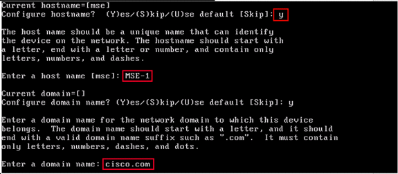
-
Configure Ethernet Interface Parameters:
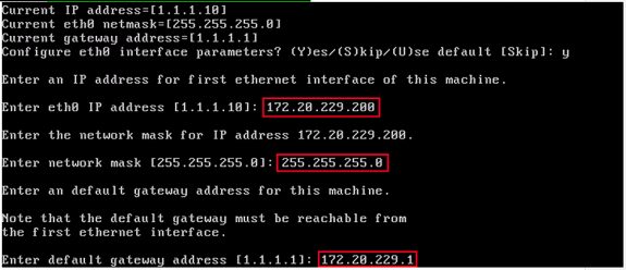
When prompted for the ‘eth1’ interface parameters, enter Skip to proceed to the next step since a second NIC is not required for operation.
Note: The address configured must provide IP connectivity to the prospective Wireless LAN controller(s) and the WCS Management system used with this appliance.
-
Enter DNS Server(s) Information: Only one DNS server is required for successful domain resolution; enter backup servers for resiliency.
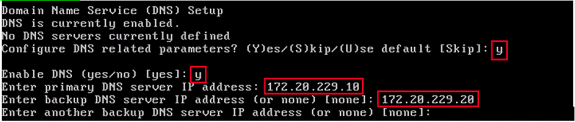
-
Configure Time Zone: If the default time zone of New York is not applicable to your environment, browse through the location menus to set it correctly.
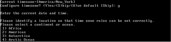
-
Configure NTP or System Time: NTP is optional, but it ensures that your system maintains an accurate system time. If you choose ‘No’ you are prompted to set the current time for the system.
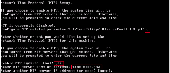
Note: It is imperative that the correct time be set on the Mobility Services Engine, Wireless LAN Controller, and WCS Management System. This can be achieved if you point all three systems to the same NTP server and ensure that they have the correct time zones configured.
-
Enable Local Console Root Login: This parameter is used to enable/disable local console access to the system. This must be enabled, so local troubleshooting can occur.
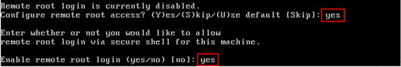
-
Enable SSH (Secure Shell) Root Login: Optional: This parameter is used to enable/disable remote console access to the system. This must be enabled, so remote troubleshooting can occur, but corporate security policies can mandate that you disable this option.
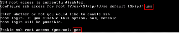
-
Configure Single User Mode and Password Strength: These configuration parameters are not required, and the default setting is to skip them is to enter ‘s’.
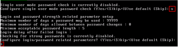
-
Set Login Banner: A login banner is used to inform users of the use of the system and present a warning to keep unauthorized users from accessing the system. Since the login banner can be a multi-line message, a single period (.) ends the message and proceeds to the next step.
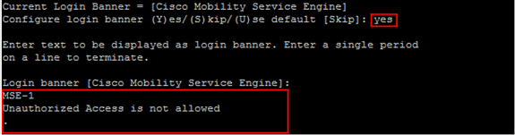
-
Change the Root Password: This step is critical to ensure system security; be sure to pick a strong password that consists of letters and numbers with no dictionary words. The minimum password length is 8 characters.
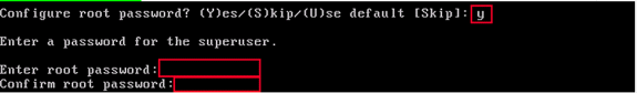
-
Configure a GRUB Password: Optional: This configuration parameter is not required, and the default setting to skip it is to enter ‘s’.

-
Configure a WCS Communication Password.
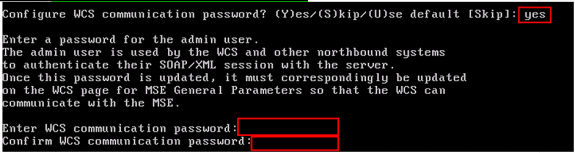
-
Save Changes and Reboot: Once the setup script has completed, save your changes when prompted. After you save, follow the prompts to reboot the MSE, as well as to ensure that all settings are applied successfully.
-
Start the MSE Service: Login to the MSE with the username root and password previously configured in Step 12. Execute the command service msed start to start the MSE service.
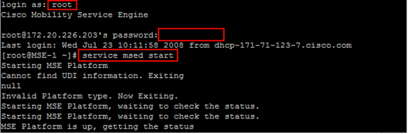
-
Enable the MSE Service to Start at Bootup: Execute the command chkconfig msed on.
Add the MSE to WCS
Complete these steps:
-
Navigate to the Mobility Services Configuration Page: Log in to WCS, and click Mobility Services from the Mobility drop-down menu.
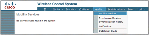
-
Add the Mobility Services Engine to WCS: From the drop-down menu on the right hand side, choose Add Mobility Services Engine, and click Go.
Enter a unique device name for the MSE, the IP address previously configured within the MSE setup, a contact name for support, and the “WCS Communication Password” configured at the MSE setup. Do not change the username from the default of admin.
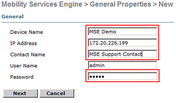
-
Choose the Context Aware Service to Run on the MSE.
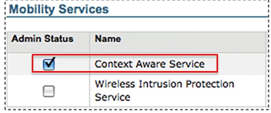
-
Synchronize: Make sure to synchronize Network Designs, Controllers and Event Groups.
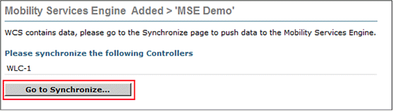
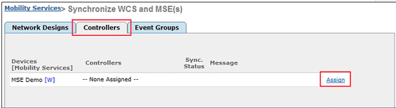
-
Controllers to Synchronize: A popup displays with a list of controllers to synchronize the MSE with. Choose the desired controllers for synchronization, and click OK.
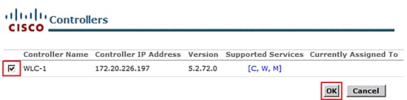
After the popup window has closed, click Synchronize at the bottom of the “Synchronize WCS and MSE(s) dialog.”
Note: The Cisco Context Aware Service is highly dependent upon a synchronized clock amongst the Wireless LAN Controller, WCS, and MSE. If all three of these systems are not pointed to the same NTP server and configured with the same time zone settings, Context Aware does not function correctly. Before you attempt to troubleshoot, ensure that the system clock is the same on all components of the Context Aware system.
Appendix B: WLC and MSE Commands
WLC Commands
config location expiry ?
client         Timeout for clients
calibrating-client Timeout for calibrating clients
tags           Timeout for RFID tags
rogue-aps      Timeout for Rogue APs

show location ap-detect ?
all            Display all (client/rfid/rogue-ap/rogue-client) information
client         Display client information
rfid           Display rfid information
rogue-ap       Display rogue-ap information
rogue-client   Display rogue-client information
(Cisco Controller) >show location ap-detect client

show client summary
Number of Clients................................ 7
MAC Address       AP Name           Status        WLAN/Guest-Lan Auth Protocol Port Wired
----------------- ----------------- ------------- -------------- ---- -------- ---- -----
00:0e:9b:a4:7b:7d AP6               Probing       N/A            No   802.11b  1    No
00:40:96:ad:51:0c AP6               Probing       N/A            No   802.11b  1    No
(Cisco Controller) >show location summary
 Location Summary
 Algorithm used:                 Average
 Client
        RSSI expiry timeout:     5 sec
        Half life:               0 sec
        Notify Threshold:        0 db
 Calibrating Client
        RSSI expiry timeout:     5 sec
        Half life:               0 sec
 Rogue AP
        RSSI expiry timeout:     5 sec
        Half life:               0 sec
        Notify Threshold:        0 db
 RFID Tag
        RSSI expiry timeout:     5 sec
        Half life:               0 sec
        Notify Threshold:        0 db

show rfid config

RFID Tag data Collection......................... Enabled
RFID  timeout.................................... 1200 seconds
RFID mobility.................................... Oui:00:14:7e : Vendor:pango  State:Disabled

(Cisco Controller) >config location ?
plm            Configure Path Loss Measurement (CCX S60) messages
algorithm      Configures the algorithm used to average RSSI  and SNR values
notify-threshold Configure the LOCP notification threshold for RSSI measurements
rssi-half-life Configures half life when averaging two RSSI readings
expiry         Configure the timeout for RSSI values

config location expiry client ?
<seconds>      A value between 5 and 3600 seconds

config location rssi-half-life client ?
<seconds>      Time in seconds (0,1,2,5,10,20,30,60,90,120,180,300 sec)

show nmsp subscription summary
Mobility Services Subscribed:
Server IP                Services
---------                --------
172.19.32.122            RSSI, Info, Statistics, IDS
MSE Commands
to determine status of MSE services
[root@MSE ~]# getserverinfo

to start Context Aware engine for client tracking
[root@MSE ~]# /etc/init.d/msed start

to determine status of Context Aware engine for client tracking
[root@MSE ~]# /etc/init.d/msed status

to stop Context Aware engine for client tracking
[root@MSE ~]# /etc/init.d/msed stop

diagnostics command
[root@MSE ~]# rundiag
Note: The rundiag command can also be used to view MSE UDI information that is required to obtain the license file for Context Aware Engine for clients.
Appendix C: MSE Upgrade from 5.X to 6.0
Complete these steps:
-
Back up the pre 6.x image MSE database from WCS; navigate to this link: Service >Mobility Services >select MSE >Maintenance >Backup.
-
In order to back up data and configuration for tags, follow the AeroScout Documentation
. -
Download 6.x image onto MSE from WCS; navigate to this link: Services >Mobility Service > choose MSE then from left pane, go to Maintenance >Download Software, browse to choose the MSE image from your PC, and click Download. Once downloaded, the MSE image automatically gets unzipped and put into the /opt/installers folder of MSE. You have to manually install the image from MSE CLI.
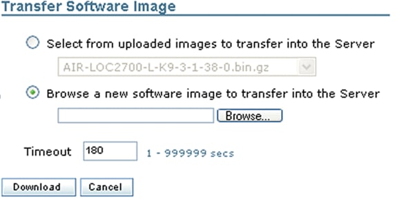
-
Issue this command to stop the MSE framework: /etc/init.d/msed stop.
-
From the MSE console, issue cd /opt/installers. In this directory, you see the file you downloaded in Step 3. The directory looks like this:
[root@heitz-3350 installers]# cd /opt/installers
[root@heitz-3350 installers]# ls
CISCO-MSE-L-K9-6-0-73-0-64bit.bin  diagnostics.log
CISCO-MSE-L-K9-6-0-75-0-64bit.bin  MSE_6_0_70_0.bin
[root@heitz-3350 installers]#
-
In order to install the MSE image, execute the file and follow the prompts:
[root@heitz-3350 installers]# ./CISCO-MSE-L-K9-6-0-73-0-64bit.bin
Note: Warning message for license requirements on MSE to track elements appears upfront with 6.0 MR1 release onwards. This warning message also appears in the end after the installation is complete. With the 6.0 release this message only appears in the end after the installation is complete. Upfront warning has been added with 6.0 MR1 to give extra alert to the user about the licensing enforcement.
The message looks like this: “Licensing on the Mobility Services Engine will be enforced with this release of software. Please ensure you have the Product Authorization Key (PAK) available and refer to the instructions outlined in the paper PAK certificate and the MSE User Guide to enable licensing on the system.”
Within the execution of the file, the user has the option to keep database or remove it.
-
Once the image is installed, execute this command to start the MSE framework: /etc/init.d/msed start .
-
MSE starts to use the evaluation licenses that are included with 6.0 software release.
-
Add the permanent license that you have received by registering a PAK number from WCS; navigate to this link: Administration > License Center > Files > MSE Files > Add . Choose MSE from the drop-down menu, browse for the license file on your PC, and upload it.
-
MSE services restart after the license is uploaded to MSE, so wait several minutes before you perform any other operation. Obtain the MSE status when you issue the /etc/init.d/msed status command.
-
Within installation of the MSE image, if you chose to keep the database option as in Step 6, you do not need to restore the previously backed up database (for clients and tags); otherwise you do need to restore the MSE database. Navigate to Service >Mobility Services, choose MSE from left panel Maintenance, and click Restore.
Note: In order to restore tag information, follow the AeroScout Documentation
.
Appendix D: MSE Database Restore
MSE DB can be restored in three different ways:
-
Option 1:
While you upgrade the MSE image to 6.0, choose to continue when the installer finds that the MSE is already running. The message shows this: “The system appears to have a Cisco Mobility Services Engine already installed. If you choose Continue, all the currently installed components will be removed permanently (Only database and license files will be preserved).”
-
Option 2:
While you uninstall the MSE image, you have two options. The first option is to keep the database, and second option is to remove the database. If the database is kept, no manual restore is required. If the database is removed, follow the third option.
-
Option 3:
Perform a fresh install, which means that you either take a new MSE box with a pre 6.0 image or an MSE with the database removed. You need to restore the backed up database (see Option 1 to MSE running 6.0).
If the backed up MSE image has been restored to another MSE, the license needs to be re-hosted so that it can be used on the current MSE. MSE licenses are tied to MSE UDI.
Within the restore, the user receives a message in WCS: “You may have to re-host the licenses if you are restoring the backup to a different MSE appliance.”
Related Information
- Cisco 3350 Mobility Services Getting Started Guide
- Cisco 3310 Mobility Services Engine Getting Started Guide
- Cisco Mobility Services Engine - Context Aware Mobility Solution Deployment Guide
- Mobility Groups FAQ
- Wi-Fi Location-Based Services 4.1 Design Guide
- Cisco 3300 Series Mobility Services Engine Licensing and Ordering Guide
- RFID Tags, a closer look to them and to their configuration
- Cisco Aironet Antennas and Accessories Reference Guide
- AeroScout Support
- Technical Support & Documentation - Cisco Systems
Revision History
| Revision | Publish Date | Comments |
|---|---|---|
1.0 |
02-Oct-2014
|
Initial Release |
 Feedback