Feedback
Table Of Contents
Context-Aware Planning and Verification
Planning for Data, Voice, and Location Deployment
Creating and Applying Calibration Models
Inspecting Location Readiness and Quality
Inspecting Location Readiness Using Access Point Data
Inspecting Location Quality Using Calibration Data
Using the Location Accuracy Tool to Test Location Accuracy
Using Scheduled Accuracy Testing to Verify Accuracy of Current Location
Using On-Demand Location Accuracy Testing
Using Chokepoints to Enhance Tag Location Reporting
Adding Chokepoints to the Cisco WCS
Removing Chokepoints from Cisco WCS
Using Wi-Fi TDOA Receivers to Enhance Tag Location Reporting
Adding Wi-Fi TDOA Receivers to Cisco WCS
Removing Wi-Fi TDOA Receivers from Cisco WCS
Using Tracking Optimized Monitor Mode to Enhance Tag Location Reporting
Defining Inclusion and Exclusion Regions on a Floor
Defining an Inclusion Region on a Floor
Defining an Exclusion Region on a Floor
Defining a Rail Line on a Floor
Modifying Context-Aware Service Parameters
Modifying Filtering Parameters
Enabling Notifications and Configuring Notification Parameters
Filtering Northbound Notifications
Configuring Notification Parameters
Configuring a Location Template
Enabling Location Services on Wired Switches and Wired Clients
Adding a Catalyst Switch to Cisco WCS
Assigning and Synchronizing a Catalyst Switches to a Mobility Services Engine
Verifying a NMSP Connection to a Mobility Services Engine
Context-Aware Planning and Verification
This chapter describes a number of tools and configurations that can be used to enhance the location accuracy of elements (clients, tags, rogue clients, and rogue access points) within an indoor or outdoor area.
Context-Aware Service (CAS) installed on a mobility services engine retrieves location information as well as other contextual information such as temperature and asset availability about a client or tag (Cisco CX version 1 or later) from access points.
Note
Non-Cisco CX tags are not tracked or mapped by Cisco WCS.
Note
This chapter contains the following sections:
•
•
•
•
•
•
•
•
•
•
•
•
You must purchase licenses from Cisco to retrieve contextual information on tags and clients from access points. Licenses for tags and clients are offered separately. (The clients license also includes tracking of rogue clients and rogue access points).
Refer to the Cisco 3300 Series Mobility Services Engine Licensing and Ordering Guide:
http://www.cisco.com/en/US/products/ps9742/products_data_sheets_list.html
For details on adding client and tag licenses to the mobility services engine, refer to Chapter 2.
Planning for Data, Voice, and Location Deployment
You can calculate the recommended number and location of access points based on the services (data, voice, location, or a combination) that are active.
To calculate the recommended number and placement of access points on a floor, follow these steps:
Step 1
Step 2
If you selected a building map, select a floor map from the Building View window.
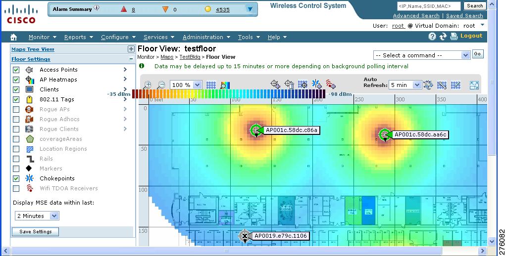
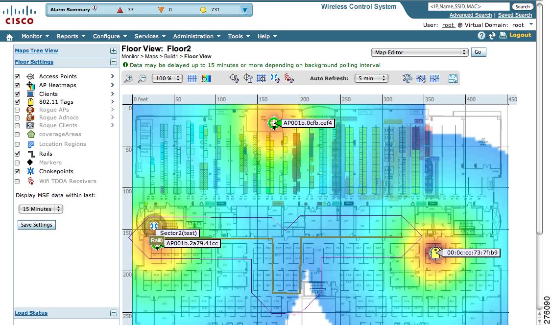
Figure 7-1 Monitor > Maps > Device Name Window
A map appears showing placement of all installed elements (access points, clients, tags) and their relative signal strength (RSSI). RSSI is indicated by the colored rings that surround the element. To identify the exact RSSI for that element, refer to the RSSI legend (color bar) at the top of the page.
Note
Step 3
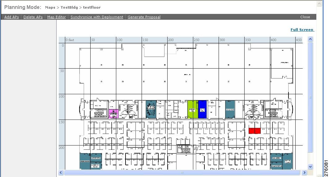
A map appears with planning mode options at the top of the window (see Figure 7-2).
Figure 7-2 Planning Mode Window
Step 4
In the window that appears, drag the dashed rectangle over the map location for which you want to calculate the recommended access points.
Note
Step 5
The recommended number of access points appears.
Note
Note
Step 6
Note
Creating and Applying Calibration Models
If the provided RF models do not sufficiently characterize your floor layout, you can create and apply a calibration model to your floor that better represents its attenuation characteristics. In environments in which many floors share common attenuation characteristics (such as in a library), you can create one calibration model and apply it to floors with the same physical layout and same deployment.
You can collect data for a calibration using one of two methods:
•
•
Note
Note
Use a laptop or other wireless device to open a browser to Cisco WCS and perform the calibration process.
To create and apply data point and linear calibration models, follow these steps:
Step 1
Step 2
Step 3
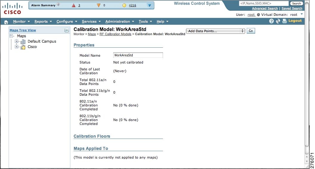
The new model appears along with the other RF calibration models, but its status is listed as Not Yet Calibrated.
Step 4
Figure 7-3 New Calibration Model Details Window
Note
Step 5
Step 6
Step 7
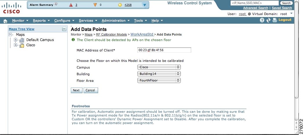
Figure 7-4 Starting to Calibrate
Step 8
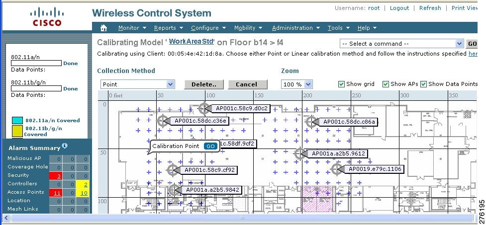
Using these locations as guidelines, you can perform either a point or linear data collection by appropriate placement of either the Calibration Point pop-up (point) or the Start and Finish pop-ups (linear) that appear on the map when the respective options appear. Figure 7-5 shows the starting window for a point calibration.
Figure 7-5 Positioning Calibration Points
a.
1.
2.
Note
3.
Note
Note
4.
Note
b.
1.
2.
3.
4.
Note
5.
Note
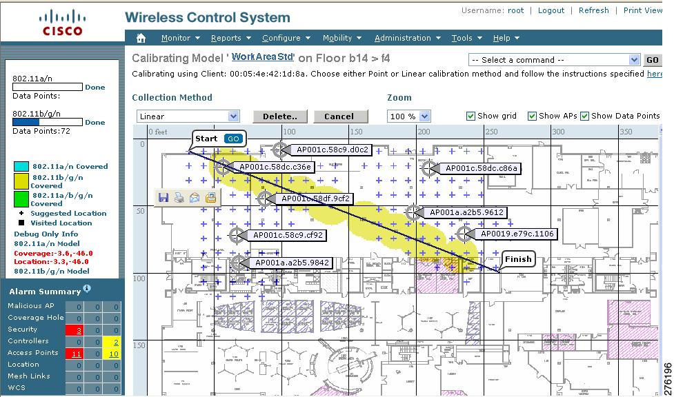
Figure 7-6 Linear Data Collection
Note
6.
Note
Step 9
Step 10
Step 11
Step 12
Step 13
Note
Inspecting Location Readiness and Quality
You can configure Cisco WCS to verify the ability of an existing access point deployment to estimate the true location of a client, rogue client, rogue access point, or tag within 10 meters at least 90% of the time. Location readiness calculation is determined the by number and placement of access points.
Using data points gathered during a physical inspection and calibration you can verify that a location meets the location specification (10m, 90%).
Inspecting Location Readiness Using Access Point Data
To inspect location readiness using access point data, follow these steps:
Step 1
Step 2
A map appears showing placement of all installed access points, clients, and tags and their relative signal strength.
Note
Note
Note
Step 3
A color-coded map appears showing those areas that do (Yes) and do not (No) meet the 10 meter, 90% location specification.
Inspecting Location Quality Using Calibration Data
After completing a calibration model based on data points generated during a physical tour of the area, you can inspect the location quality of the access points.
To inspect location quality based on calibration, follow these steps:
Step 1
Step 2
A list of defined calibration models appears.
Step 3
Details on the calibration including date of last calibration, number of data points by signal type (802.11a, 802.11 b/g) used in the calibration, location, and coverage are displayed.
Step 4
A color-coded map noting percentage of location errors appears.
Note
Verifying Location Accuracy
By verifying for location accuracy, you are ensuring that the existing access point deployment can estimate the true location of an element within 10 meters at least 90% of the time.
You can analyze the location accuracy of non-rogue and rogue clients and asset tags by using the Accuracy Tool.
The Accuracy Tool enables you to run either a scheduled or on-demand location accuracy test. Both tests are configured and executed through a single window.
Using the Location Accuracy Tool to Test Location Accuracy
There are two ways to test location accuracy:
•
•
Both are configured and executed through a single window.
Using Scheduled Accuracy Testing to Verify Accuracy of Current Location
To configure a scheduled accuracy test, follow these steps:
Step 1
Step 2
Step 3
Step 4
Step 5
Step 6
Step 7
Step 8
Note
Step 9
Note
Step 10
Step 11
When you check the MAC address check box for a client or tag, two overlapping icons appear on the map for that element.
One icon represents the actual location and the other the reported location.
Note
Step 12
Note
Step 13
Step 14
Note
Step 15
The Scheduled Location Accuracy Report includes the following information:
•
•
•
•
•
Using On-Demand Location Accuracy Testing
An on-demand accuracy test is run when elements are associated but not pre-positioned. On-demand testing allows you to test the location accuracy of clients and tags at a number of different locations. You generally use it to test the location accuracy for a small number of clients and tags.
To run an on-demand accuracy test, follow these steps:
Step 1
Step 2
Step 3
Step 4
Step 5
Step 6
Step 7
Step 8
Step 9
Step 10
Step 11
Step 12
Step 13
Step 14
Step 15
Step 16
The on-demand accuracy report includes the following information:
•
•
•
Step 17
a.
b.
The Download Logs option downloads the logs for all accuracy tests for the selected test(s).
The Download Logs for Last Run option downloads logs for only the most recent test run for the selected test(s).
Using Chokepoints to Enhance Tag Location Reporting
Installing chokepoints (also known as exciters) provides enhanced location information for active RFID tags. When an active Cisco CX version 1 compliant RFID tag enters the range of a chokepoint, it is stimulated by the chokepoint. The MAC address of this chokepoint is then included in the next beacon sent by the stimulated tag. All access points that detect this tag beacon then forward the information to the controller and mobility services engine.
Using chokepoints in conjunction with active Cisco CX compliant tags provides immediate location information on a tag and its asset. When a Cisco CX tag moves out of the range of a chokepoint, its subsequent beacon frames do not contain any identifying chokepoint information. Location determination of the tag defaults to the standard calculation methods based on RSSIs reported by access point associated with the tag.
Note
Adding Chokepoints to the Cisco WCS
After you install and configure the chokepoint using Aeroscout System Manager, you can add the chokepoint to the location database and position it on a Cisco WCS map.
To add a chokepoint to Cisco WCS, follow these steps:
Step 1
The Chokepoints summary window appears.
Step 2
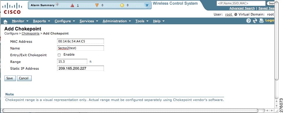
The Add Chokepoint entry screen appears (see Figure 7-7).
Figure 7-7 Add Chokepoint Window
Step 3
Note
Step 4
Tip
Step 5
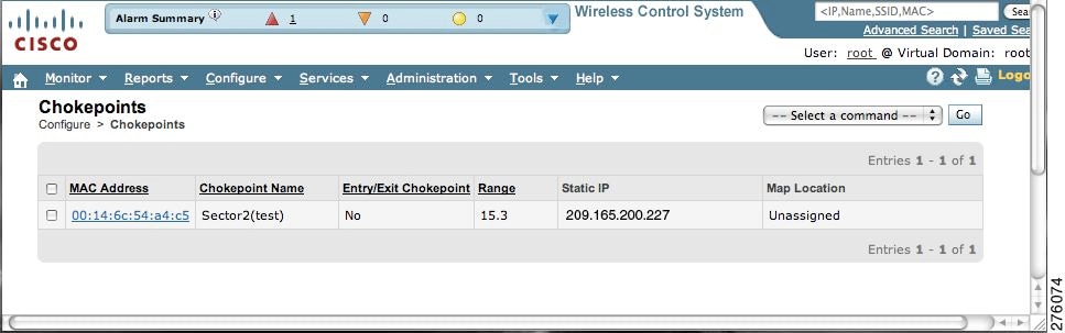
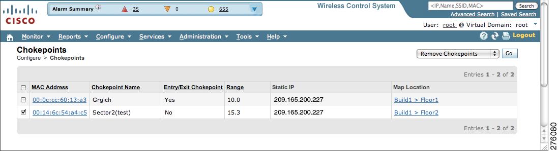
The Chokepoints summary window appears with the new chokepoint entry listed (see Figure 7-8).
Figure 7-8 Chokepoints Summary Window
Note
Step 6
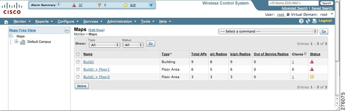
Figure 7-9 Monitor > Maps Window
Step 7
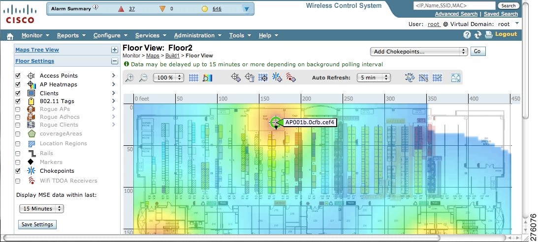
Figure 7-10 Selected Floor Map Window
Step 8
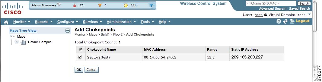
The Add Chokepoints summary window appears (see Figure 7-11).
Note
Figure 7-11 Add Chokepoints Summary Window
Step 9
A map appears with a chokepoint icon in the top-left corner. You can now place the chokepoint on the map.
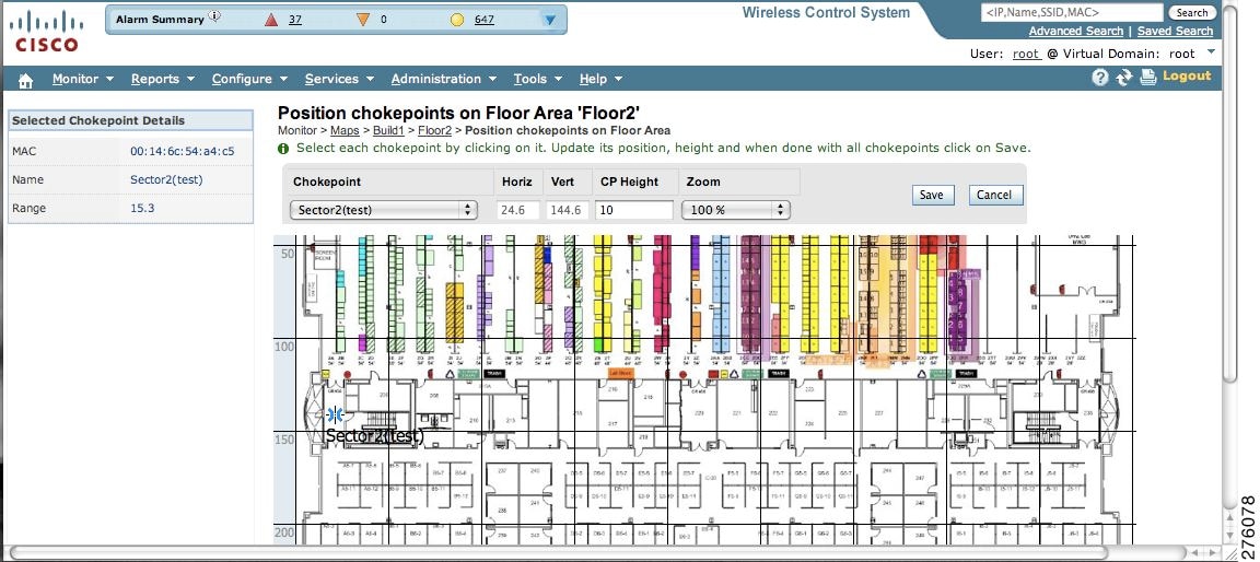
Step 10
Figure 7-12 Chokepoint Icon is Positioned on the Floor Map
Note
Step 11
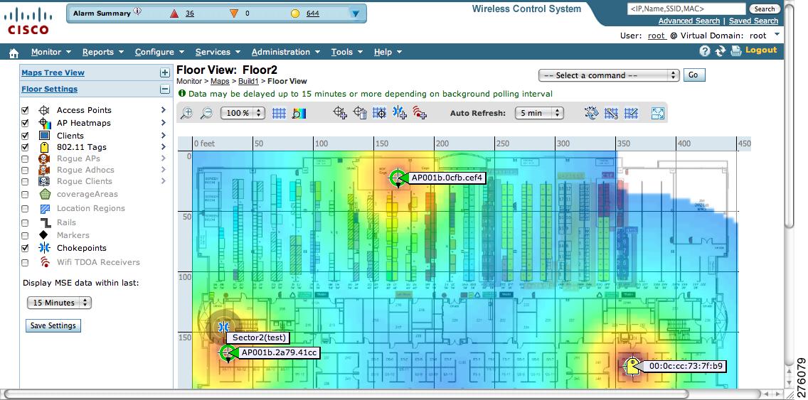
The floor map reappears with the added chokepoint (see Figure 7-13).
Note
Figure 7-13 New Chokepoint Displayed on Floor Map
Note
Note
Removing Chokepoints from Cisco WCS
You can remove one or more chokepoints at a time.
To delete a chokepoint, follow these steps:
Step 1
Step 2
Step 3
Figure 7-14 Removing a Chokepoint
Step 4
The Chokepoints window reappears and confirms deletion of the chokepoints. The deleted chokepoints are no longer listed in the window.
Using Wi-Fi TDOA Receivers to Enhance Tag Location Reporting
The Wi-Fi TDOA receiver is an external system designed to receive signals transmitted from a tagged, tracked asset. These signals are then forwarded to the mobility services engine for used in calculating location of a tagged asset. TDOA receivers use the Time Difference of Arrival (TDOA) method to calculate tag location. TDOA uses data from a minimum of three TDOA receivers to generate a tagged asset's location.
Note
Before using a TDOA receiver within the Cisco Unified Wireless Network, you must:
1.
Refer to Chapter 2, "Adding and Deleting Mobility Services Engines and Licenses," for details on adding a mobility services engine.
2.
Refer to the "Adding Wi-Fi TDOA Receivers to Cisco WCS" section for details on adding the TDOA receiver to Cisco WCS.
3.
Refer to Chapter 3, "Synchronizing Mobility Services Engines," for details on synchronization.
4.
Note
Adding Wi-Fi TDOA Receivers to Cisco WCS
After you add TDOA receivers to Cisco WCS maps and synchronize, use the AeroScout System Manager application rather than Cisco WCS to modify the TDOA receiver configuration.
Note
To add a TDOA receiver to the Cisco WCS database and appropriate map, follow these steps:
Step 1
Step 2
Step 3
Step 4
Note
Step 5
Step 6
Step 7
Note
Figure 7-15 Monitor > Maps > Add WiFi TDOA Receivers Window
Step 8
The Add WiFi TDOA Receivers summary window appears.
Note
Step 9
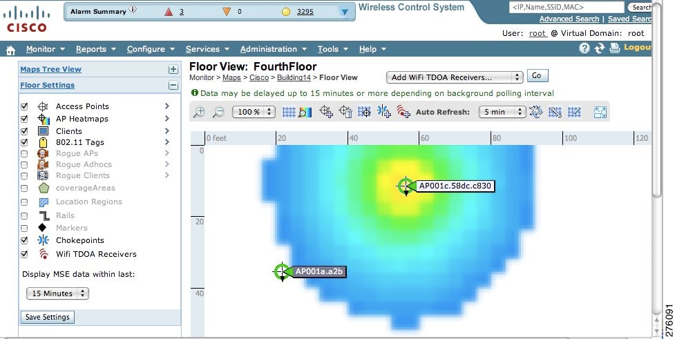
A map appears with a TDOA receiver icon in the top-left corner. You are now ready to place the TDOA receiver on the map (see Figure 7-16).
Figure 7-16 Placing WiFi TDOA Receiver on the Map
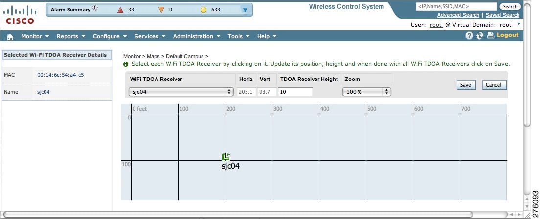
Step 10
Note
Note
Step 11
Step 12
The floor heat map reappears with the added TDOA receiver.
Note
Removing Wi-Fi TDOA Receivers from Cisco WCS
You can remove one or more Wi-Fi TDOA receivers at a time. If you remove a TDOA receiver from a map it remains in the WCS database but is labeled as unassigned.
To delete a TDOA receiver from WCS, follow these steps:
Step 1
Step 2
Step 3
Step 4
The All WiFi TDOA Receivers window. A message confirming deletion of the TDOA receiver appears. The deleted TDOA receiver is no longer listed in the window.
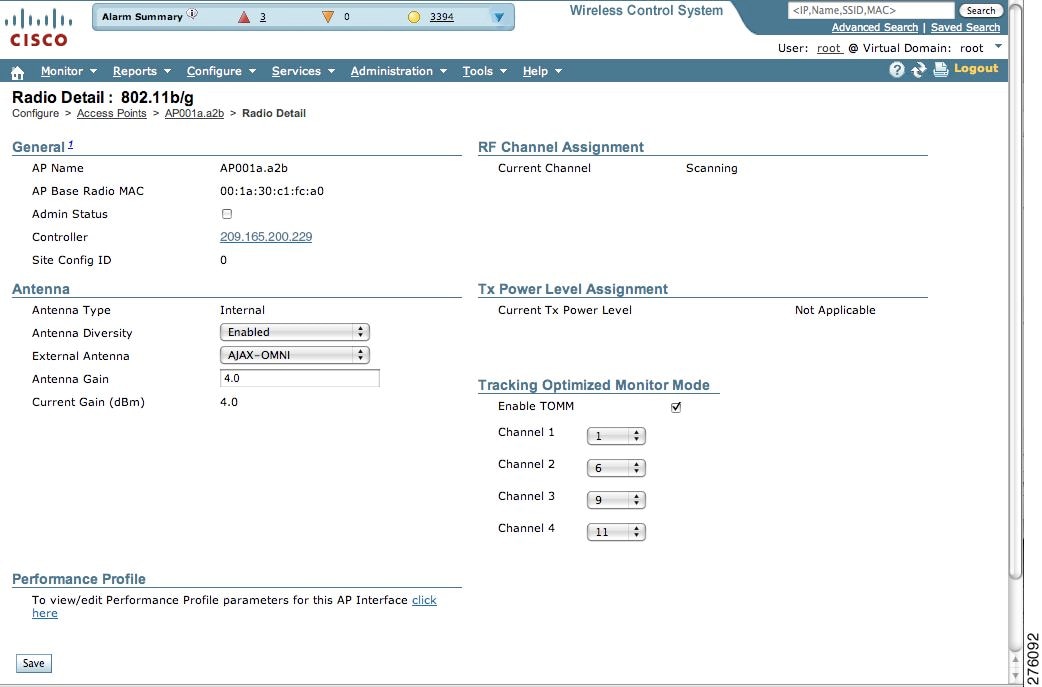
Using Tracking Optimized Monitor Mode to Enhance Tag Location Reporting
To optimize monitoring and location calculation of tags, you can enable TOMM on up to four channels within the 2.4-GHz band (802.11b/g radio) of an access point. This allows you to focus channel scans only on those channels on which tags are usually programmed to operate (such as channels 1, 6, and 11).
You must enable monitor mode at the access point level before you can enable TOMM and assign monitoring channels on the 802.11 b/g radio of the access point.
Step 1
a.
b.
Note
Step 2
a.
b.
c.
Figure 7-17 Configure > Access Point > 802.11 b/g
d.
e.
Note
f.
g.
h.
The AP Mode appears as Monitor on the Monitor > Access Points window.
Defining Inclusion and Exclusion Regions on a Floor
To further refine location calculations on a floor, you can define the regions that are included (inclusion areas) in the calculations and those regions that are not included (exclusion regions).
For example, you might want to exclude regions such as an atrium or stairwell within a building but include a work area (such as cubicles, labs, or manufacturing floors).
Note
Guidelines
Consider the following when configuring exclusion and inclusion areas:
•
•
•
•
•
Defining an Inclusion Region on a Floor
To define an inclusion region, follow these steps:
Step 1
Step 2
Step 3
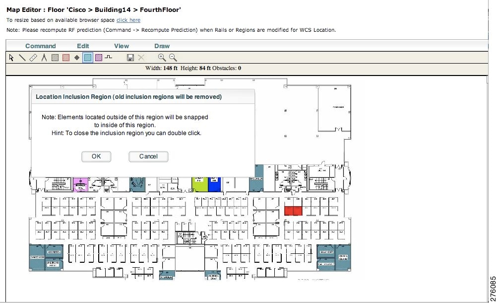
Step 4
A message box appears reminding you that only one inclusion region can be defined at a time. Defining a new inclusion region automatically removes the previously defined inclusion region. By default, an inclusion region is defined for each floor when it is added to Cisco WCS.
Figure 7-18 Map Editor Window
Step 5
Step 6
Step 7
Step 8
Figure 7-19 Inclusion Area Defined
Step 9
Note
Step 10
Step 11
Step 12
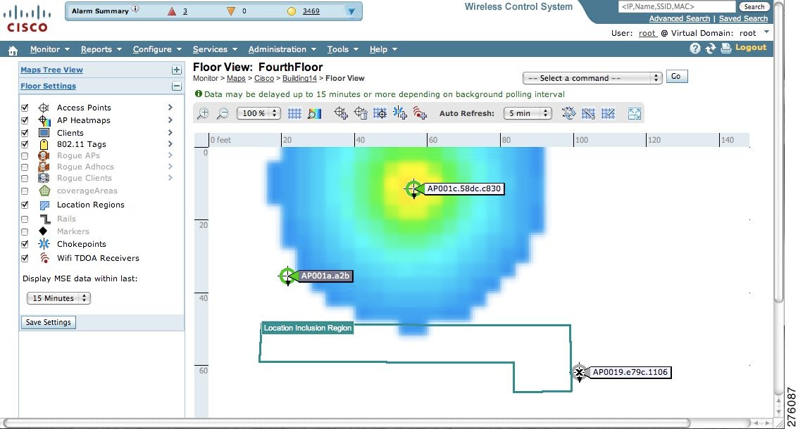
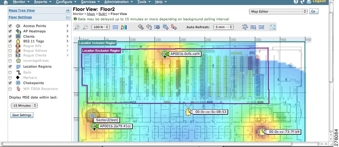
The defined inclusion region appears on the map (see Figure 7-20).
Figure 7-20 Monitor > Maps > Floor
Step 13
Step 14
Look at the Sync. Status column to ensure that the synchronization is successful (two green arrows).
Note
Defining an Exclusion Region on a Floor
To further refine location calculations on a floor, you can define regions that are excluded (exclusion regions) in the calculations.Exclusion regions are generally defined within the borders of an inclusion region.
To define an exclusion region, follow these steps:
Step 1
Step 2
Step 3
Step 4
Step 5
Step 6
Step 7
Step 8
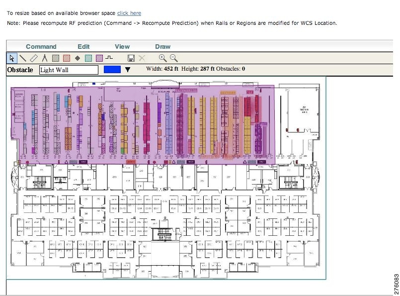
Step 9
Figure 7-21 Defining Exclusion Areas on Floor Map
Step 10
Note
Step 11
Step 12
Figure 7-22 Location Exclusion Region
Step 13
Step 14
Check the Sync. Status column to ensure that the synchronization is successful (two green arrows).
Defining a Rail Line on a Floor
You can define a rail line on a floor (such as a conveyor belt) that indicates an area where clients are expected to be.
Note
Additionally, you can define an area (east and west or north and south) of the rail that expands the area that clients are expected to populate. This expanded area is known as the snap-width and further assists location calculations. Any client located within the snap-width area is plotted on the rail line (majority) or just outside of the snap-width area (minority).
The snap-width area is defined in feet or meters (user-defined).
To define a rail on a floor, follow these steps:
Step 1
Step 2
Step 3
Step 4
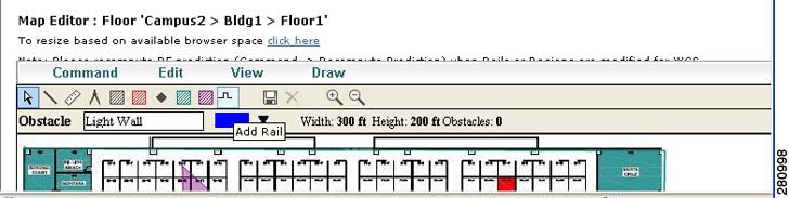
Figure 7-23 Rail Icon on Map Editor Tool Bar
Step 5
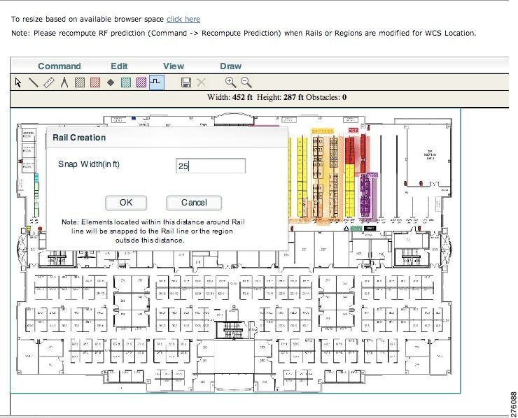
Figure 7-24 Defining Rail Width
Step 6
Step 7
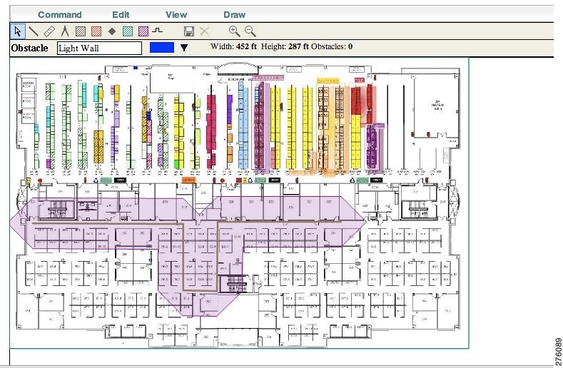
Figure 7-25 Defining Rail Line in Map Editor
Note
Step 8
Step 9
Figure 7-26 Rail Line on Heat Map
Step 10
Step 11
Look at the Sync. Status column to ensure that the synchronization is successful (two green arrows).
Modifying Context-Aware Service Parameters
You can specify the type and number of clients or tags that are tracked and whether or not locations are calculated for those clients or tags.
You can also modify parameters that affect the location calculation of clients and tags such as Receiver Signal Strength Indicator (RSSI) measurements.
Note
Modifying Tracking Parameters
The mobility services engine can track up to 18,000 clients (including rogue clients, rogue access points, and wired clients) and tags (combined count) with the proper license purchase and mobility services enigne. Updates on the locations of tags and clients being tracked are provided to the mobility services engine from the controller.
Note
Only those tags and clients that the controller is tracking are seen in Cisco WCS maps, queries and reports. No events and alarms are collected for non-tracked elements and none are used in calculating the 18,000 element limit for clients or tags.
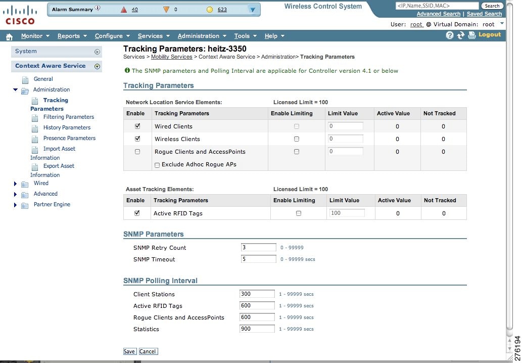
You can modify the following tracking parameters using Cisco WCS:
•
Wired client location tracking enables servers in a data center to more easily find wired clients in the network. Servers are associated with wired switch ports in the network.
•
For example, given a client license of 12,000 trackable units, you could set a limit to track only 8,000 client stations (leaving 4,000 units available to allocate between rogue clients and rogue access points). Once the tracking limit is met for a given element, the number of elements not being tracked is summarized on the Tracking Parameters page.
•
To configure tracking parameters for a mobility services engine, follow these steps:
Step 1
Step 2
Step 3
Figure 7-27 Context Aware Service > Administration > Tracking Parameters
Step 4
:
Step 5
Modifying Filtering Parameters
In addition to tracking parameters, you can use filtering to limit the number of clients, tags, and rogue clients and access points whose locations are tracked. You can filter by MAC address and probing clients.
•
Specific MAC addresses can be entered and labeled as allowed or disallowed from location tracking. You can import a file with the MAC addresses that are to be allowed or disallowed, or you can enter them individually from the WCS GUI window.
The format for entering MAC addresses is xx:xx:xx:xx:xx:xx. If a file of MAC addresses is imported, the file must follow a specific format as noted below:
–
–
–
Note
EXAMPLE file listing:
[Allowed]
00:11:22:33:*
22:cd:34:ae:56:45
02:23:23:34:*
[Disallowed]
00:10:*
ae:bc:de:ea:45:23•
Probing clients are clients that are associated with one controller but whose probing activity enables them to appear to another controller and count as an element for the probed controller as well as its primary controller.
To configure filtering parameters for a mobility services engine, follow these steps:
Step 1
Step 2
Step 3
Step 4
Step 5
Modifying History Parameters
You can use Cisco WCS to specify how long to store (archive) histories on client stations, asset tags, and rogue clients and access points. Controllers associated with the mobility services engine send it histories.
You can also program the mobility services engine to periodically prune (remove) duplicate data from its historical files, which increases the amount of memory available for other functions.
To configure mobility services engine history settings, follow these steps:
Step 1
Step 2
Step 3
Step 4
:
Step 5
Enabling Location Presence
You can enable location presence on a mobility services engine in order to expand civic (city, state, postal code, country) and geographic (longitude, latitude) location information beyond the Cisco default settings (campus, building, floor, and X, Y coordinates). You an then request this information for wireless and wired clients on demand for use by location-based services and applications.
You can also import advanced location information such as the MAC address of a wired client and the wired switch slot and port to which the wired client is attached.
You can configure location presence when a new campus, building, floor or outdoor area is added or configure it at a later date.
Once enabled, the mobility services engine can provide any requesting Cisco CX v5 client its location.
Note
Note
To enable and configure location presence on a mobility services engine, follow these steps:
Step 1
Step 2
Step 3
Step 4
Step 5
a.
–
b.
–
c.
–
Step 6
a.
b.
c.
Step 7
Step 8
Step 9
Step 10
Importing Asset Information
To import asset, chokepoint, and TDOA receiver information for the mobility services engine using Cisco WCS, follow these steps:
Step 1
Step 2
Step 3
Step 4
Specify information in the imported file in the following formats:
•
•
•
X, Y, and Z represent map coordinates
LS refers to the TDOA receiver
•
X, Y, and Z represent map coordinates.
CP refers to the chokepoint
IsPerimeter is only required if the chokepoint is a perimeter chokepoint
Step 5
Exporting Asset Information
To export asset, chokepoint, and TDOA receiver information from the mobility services engine to a file using Cisco WCS, follow these steps:
Step 1
Step 2
Step 3
Information in the exported file is in the following formats:
•
•
•
X, Y, and Z represent map coordinates
LS refers to the TDOA receiver
•
X, Y, and Z represent map coordinates.
IsPerimeter indicates that the chokepoint is a perimeter chokepoint.
CP refers to the chokepoint.
Step 4
Step 5
Note
Modifying Location Parameters
You can use Cisco WCS to modify parameters that affect location calculations such as Receiver Signal Strength Indicator (RSSI) measurements for clients.
You can also apply varying smoothing rates to manage location movement of a client.
Note
To configure location parameters, follow these steps:
Step 1
Step 2
Step 3
Step 4
Step 5
Enabling Notifications and Configuring Notification Parameters
Enabling Notifications
You can use Cisco WCS to define and enable user-configured conditional notifications and northbound notifications.
User-configured conditional notifications manage which notifications the mobility services engine sends to Cisco WCS. Refer to "Adding, Deleting, and Testing Event Definitions" section on page 6-2.
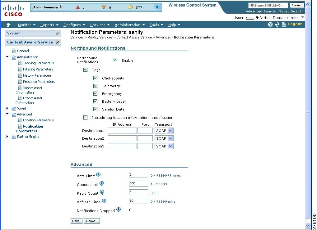
Northbound notifications define which tag notifications the mobility services engine sends to third-party applications. Client notifications are not forwarded. By enabling northbound notifications in Cisco WCS, the following five event notifications are sent: chokepoints, telemetry, emergency, battery, and vendor data. To send a tag location, you must enable that notification separately.
The mobility services engine sends all northbound notifications in a set format. Details are available on the Cisco developers support portal at:
http://www.cisco.com/en/US/products/svcs/ps3034/ps5408/ps5418/serv_home.html
Filtering Northbound Notifications
Filtering on northbound notifications is possible in release 6.0 and later. Similar to user-configured conditional notifications, you can limit which event notifications are forwarded.
You can use filtering to focus on specific notifications important to tag monitoring within your network and to limit the overall number of notifications sent. The latter might preserve processing and storage capacity on the northbound platform.
Note
You can filter on six northbound parameters as summarized below:
<entry key="send-event-on-location-calc">true</entry><entry key="send-event-on-every-beacon">true</entry><entry key="send-event-on-vendor">true</entry><entry key="send-event-on-emergency">true</entry><entry key="send-event-on-chokepoint">true</entry><entry key="send-event-on-telemetry">true</entry>To send all six northbound notifications with each beacon, ensure that the send-event-on-location-calc and send-event-on-every-beacon notification types are marked as true.
To limit the number of notifications, edit (but do not delete) the specific event entry in the aes-config.xml file by marking it as false.
For example, to send emergency and chokepoint notifications only change the other four notification types (location, beacon, vendor, and telemetry) to false.
The modified aes-config.xml file would read as:
<entry key="send-event-on-location-calc">false</entry><entry key="send-event-on-every-beacon">false</entry><entry key="send-event-on-vendor">false</entry><entry key="send-event-on-emergency">true</entry><entry key="send-event-on-chokepoint">true</entry><entry key="send-event-on-telemetry">false </entry>Configuring Notification Parameters
You can limit the rate at which a mobility services engine generates notifications, set a maximum queue size for notifications, and set a retry limit for notifications with in a certain period.
Notification parameter settings apply to user-configurable conditional notifications and northbound notifications except as noted in Table 7-5.
Note
To enable northbound notifications and to configure notification parameters, follow these steps:
Step 1
Step 2
Step 3
Figure 7-28 Mobility Services Engine > Context Aware Service > Advanced > Notification Parameters
Step 4
Step 5
Note
Step 6
Note
Step 7
Step 8
Step 9
Step 10
Configuring a Location Template
You can define a location template for the controller that you can download to multiple controllers.
You can set the following general and advanced parameters on the location template.
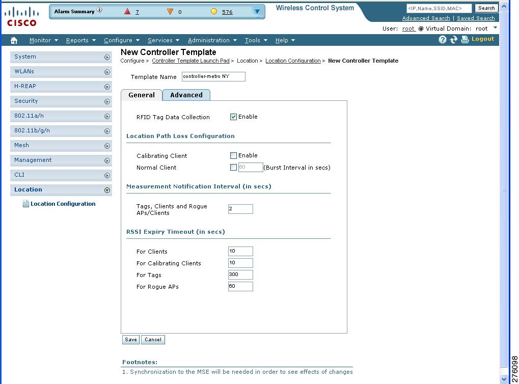
General parameters-Enable RFID tag collection, set the location path loss for calibrating or normal (non-calibrating) clients, measurement notification for clients, tags, and rogue access points, set the RSSI expiry timeout value for clients, tags, and rogue access points.
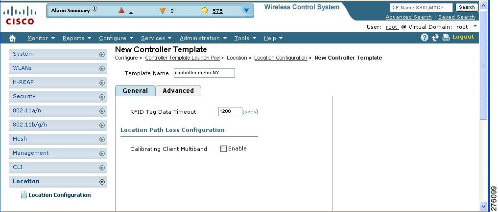
Advanced parameters-Set the RFID tag data timeout value and enable the location path loss configuration for calibrating client multi-band.
To configure a new location template for a controller, follow these steps:
Step 1
Step 2
Figure 7-29 Configure > Controller Template Launch Pad Window
Step 3
Figure 7-30 Location Configuration > New > General Panel
Step 4
Step 5
Table 7-7 describes each of the advanced parameters.
Figure 7-31 Location Configuration > New > Advanced Panel
Step 6
Enabling Location Services on Wired Switches and Wired Clients
You can import the location of wired Catalyst stackable switches (3750, 3750-E, 3560, 2960, IE-3000 switches), switch blades (3110, 3120, 3130, 3040, 3030, 3020), and switch ports into the mobility services engine.
The following Catalyst 4000 series are also supported:
WS-C4948, WS-C4948-10GE, ME-4924-10GE, WS-4928-10GE, WS-C4900M, WS-X4515, WS-X4516, WS-X4013+, WS-X4013+TS, WS-X4516-10GE, WS-X4013+10GE, WS-X45-SUP6-E, and WS-X45-SUP6-LE
Once you define a wired switch and synchronize it with a mobility services engine, details on wired clients connected to a wired switch are downloaded to the mobility services engine over the NMSP connection. You can then view wired switches and wired clients using Cisco WCS.
Import and display of civic and emergency location information (ELIN) meets specifications of RFC4776 which is outlined at:
http://tools.ietf.org/html/rfc4776#section-3.4
Note
To support location services for wired clients and wired Catalyst switches, you must do the following:
1.
2.
3.
Configuring a Catalyst Switch
To configure location service on a wired switch or wired client, and apply it to an interface, follow these steps:
Note
Step 1
Switch > enSwitch#Switch# Configure terminalStep 2
Switch(Config)# nmspSwitch(config-nmsp)# enableStep 3
Switch(config)# snmp-server community wired-locationStep 4
Switch(config)# ip device trackingStep 5
Note
Enter configuration commands, one per line. End with Ctrl-Z.
Example civic location configuration is noted below.
Switch(config)# location civic-location identifier 6Switch(config-civic)# name "switch-loc4"Switch(config-civic)# seat "ws-3"Switch(config-civic)# additional code "1e3f0034c092"Switch(config-civic)# building "SJ-14"Switch(config-civic)# floor "4"Switch(config-civic)# street-group "Cisco Way"Switch(config-civic)# number "3625"Switch(config-civic)# type-of-place "Lab"Switch(config-civic)# postal-community-name "Cisco Systems, Inc."Switch(config-civic)# postal-code "95134"Switch(config-civic)# city "San Jose"Switch(config-civic)# state "CA"Switch(config-civic)# country "US"Switch(config-civic)# endStep 6
Note
Switch(config)# location elin-location "4084084000" identifier 6Switch(config)# endStep 7
A switch has a specified number of switch ports, and clients and hosts are connected at these ports. When configuring location for a specific switch port, the client connected at that port is assumed to have the port location.
If a switch (switch2) is connected to a port (such as port1) on another switch (switch1) all the clients connected to switch2 are assigned the location that is configured on port1.
Format for defining port is: interface {GigabitEthernet | FastEthernet} slot/module/port
Enter only one location definition on a line, and end the line by entering Ctrl-Z.
Switch(config)# interface GigabitEthernet 1/0/10Switch(config-if)# location civic-location-id 6Switch(config-if)# location elin-location-id 6Switch(config-if)# endStep 8
The following is configured on the FastEthernet network management port of the switch.
Enter configuration commands, one per line. End with Ctrl-Z.
Switch(config)# interface FastEthernet 0Switch(config-if)# location civic-location-id 6Switch(config-if)# location elin-location-id 6Switch(config-if)# end
Adding a Catalyst Switch to Cisco WCS
All Catalyst switches must be configured with location service before they are added to Cisco WCS. Refer to the "Configuring a Catalyst Switch" section.
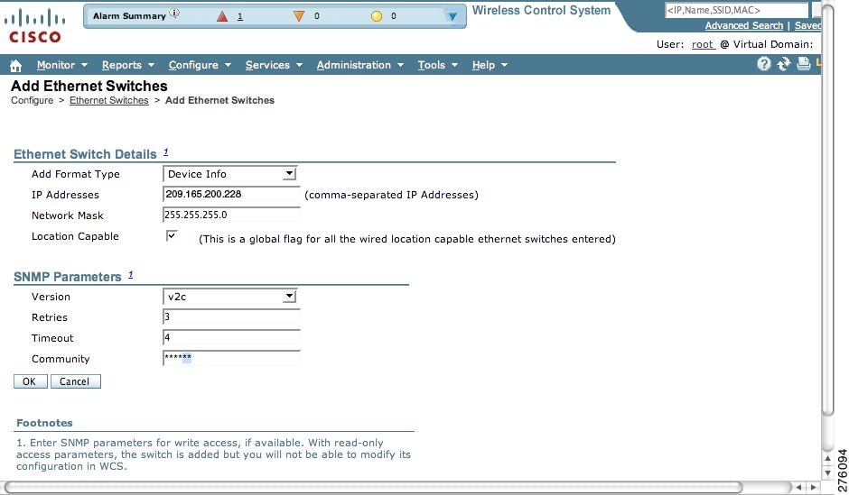
To add a Catalyst switch configured for wired location service to Cisco WCS, follow these steps:
Step 1
Step 2
Figure 7-32 Configure > Ethernet Switches > Add Ethernet Switches
Step 3
Note
Step 4
Step 5
Step 6
Step 7
Step 8
Note
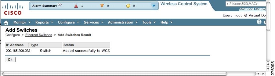
Step 9
Figure 7-33 Add Switches Result Window
Step 10
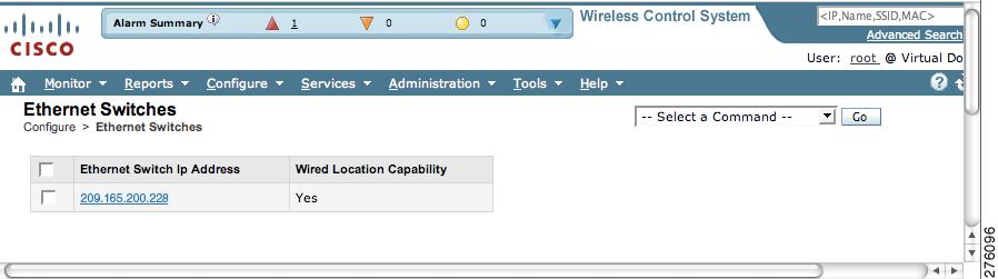
Figure 7-34 Ethernet Switches Summary Window
Assigning and Synchronizing a Catalyst Switches to a Mobility Services Engine
After adding a Catalyst switch to Cisco WCS you need to assign it to a mobility services engine and then synchronize the two systems. Once they are synchronized, an NMSP connection between the controller and the mobility services engine is established.
All information on wired switches and wired clients connected to those switches downloads to the mobility services engine.
Note
Step 1
Step 2
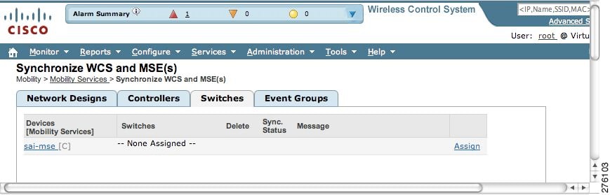
Figure 7-35 Switches Assignment Tab
Step 3
Step 4
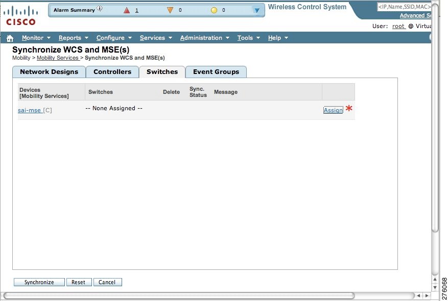
An updated switches panel within the Synchronize WCS and MSE(s) window appears (see Figure 7-36). A red asterisk (*) appears next to the Assign link.
Figure 7-36 Updated Switches Panel Showing Pending Synchronization of Switch Assignment
Step 5
To undo assignments prior to synchronization, click Reset. To go back to the Synchronize WCS and MSE(s) window without making any changes, click Cancel.
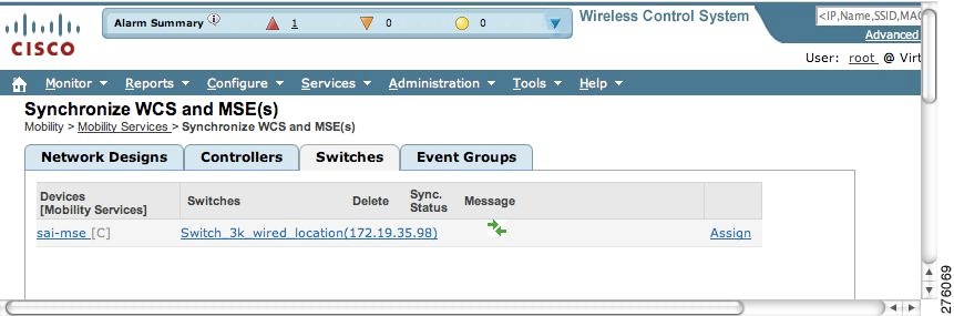
Figure 7-37 Updated Switches Panel Confirming Synchronization
Step 6
Note
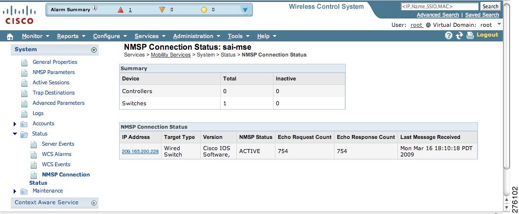
Verifying a NMSP Connection to a Mobility Services Engine
NMSP manages communication between the mobility services engine and a controller or a location-capable Catalyst switch. Transport of telemetry, emergency, and chokepoint information between the mobility services engine and the controller or location-capable Catalyst switch is managed by this protocol.
To verify a NMSP connection between a mobility services engine and a controller or a location-capable Catalyst switch, follow these steps:
Step 1
Step 2
Step 3
Figure 7-38 NMSP Connection Status
Step 4
If not active, resynchronize the Catalyst switch or controller and the mobility services engine.
Note