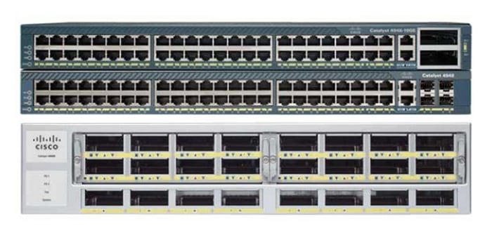
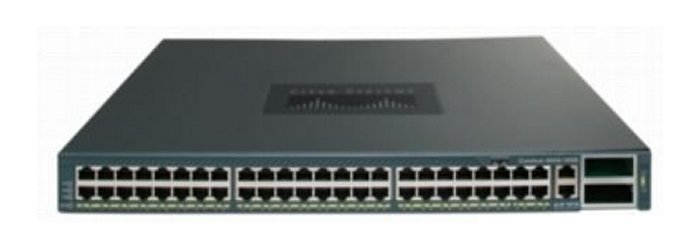
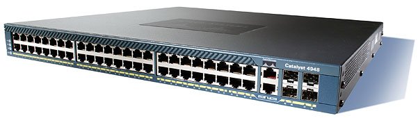
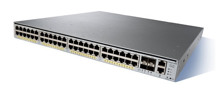
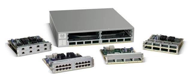
Table Of Contents
Transceiver, Chassis Connectors, and Cable and Adapter Specifications
Transceiver Support for Uplink Ports
1-GB SFP Transceivers
CWDM SFP Transceivers
DWDM SFP Transceivers
10-GB SFP+ Transceivers
Console Port
Ethernet Management Port
Cables and Adapters
Rollover Cable
Rollover Cable RJ-45 to DB-9 Adapter (For Connecting to a PC)
Transceiver, Chassis Connectors, and Cable and Adapter Specifications
Revised: January 4, 2012
This appendix covers the transceivers supported by the Catalyst 4948E and the Catalyst 4948E-F switches, the connectors on the front panel of the chassis, and the cables and adapters supplied in the accessory kit. The appendix is divided into the following topics:
•
Transceiver Support for Uplink Ports
•
Console Port
•
Ethernet Management Port
•
Cables and Adapters
Tip
For additional information about the Cisco Catalyst 4948E and the Catalyst 4948E-F switches (including configuration examples and troubleshooting information), see the documents listed on this page:
http://www.cisco.com/en/US/products/ps6021/tsd_products_support_series_home.html
Transceiver Support for Uplink Ports
Both the Catalyst 4948E and the Catalyst 4948E-F chassis have four uplink ports that support both 1-GB SFP and 10-GB SFP+ transceivers.
1-GB SFP Transceivers
Table B-1 lists the 1-GB SFP transceivers that are supported on the chassis uplink ports.
Table B-1 1-GB SFP Transceiver Support
SFP Transceiver
|
Description
|
GLC-T
|
(1000BASE-T)
|
GLC-SX-MM
|
(1000BASE-SX)
|
GLC-LH-SM
|
(1000BASE-LH/LX)
|
GLC-ZX-SM
|
(1000BASE-ZX)
|
GLC-BX-D
|
(1000BASE-BX10)
|
GLC-BX-U
|
(1000BASE-BX10)
|
The four uplink ports also support 1-GB CWDM and 1-GB DWDM SFP transceivers, which are described in separate sections.
Figure B-1 shows a 1000BASE-X (optical) SFP transceiver with the major features of the transceiver identified. Figure B-2 shows a 1000BASE-T (copper) SFP transceiver with the major features of the transceiver identified.
Figure B-1 1-GB Optical SFP Transceiver Features
Figure B-2 1-GB Copper SFP Transceiver Features
1
|
RJ-45 connector
|
3
|
Bail-clasp shown in the open (unlocked) position
|
2
|
Bail-clasp shown in the closed (locked) position
|
|
|
Table B-2 lists the specifications for the 1000BASE-T and 1000BASE-X SFP transceivers.
Table B-2 1000BASE-T and 1000BASE-X SFP Transceiver Specifications
SFP Transceiver Module and Product Number
|
Interface Connector
|
Nominal Wavelength (nm)
|
Network Cable Type
|
Fiber Core Size (micron)
|
Modal Bandwidth (MHz/km)
|
|
1000BASE-T (GLC-T=)
|
RJ-45
|
—
|
Category 5, 5e, or 6 UTP/FTP
|
—
|
—
|
328 ft (100 m)
|
1000BASE-SX (GLC-SX-MM=)
|
LC duplex
|
850
|
MMF
|
62.5 62.5 50.0 50.0
|
160 200 400 500
|
722 ft (220 m) 902 ft (275 m) 1640 ft (500 m) 1804 ft (550 m)
|
1000BASE-LX/LH (GLC-LH-SM=)
|
LC duplex
|
1300
|
MMF2
SMF
|
62.5 50.0 50.0 G.6523
|
500 400 500 —
|
1804 ft (550 m) 1804 ft (550 m) 1804 ft (550 m) 6.21 mi (10 km)
|
1000BASE-ZX (GLC-ZX-SM=)
|
LC duplex
|
1550
|
SMF
|
G.6523
|
—
|
43.4 to 62 mi (70 to 100 km)4
|
1000BASE-BX10 (GLC-BX-D=)
|
LC single
|
1490 (downstream)
|
SMF
|
G.6523
|
—
|
6.21 mi (10 km)
|
1000BASE-BX10 (GLC-BX-U=)
|
LC single
|
1310 (upstream)
|
SMF
|
G.6523
|
—
|
6.21 mi (10 km)
|
Table B-3 lists the fiber loss budgets for the 1000BASE-T and 1000BASE-X SFP transceivers.
Table B-3 Fiber Loss Budgets for the 1-GB SFP Transceivers
1-GB SFP Transceiver Product Number
|
Transmit Power (dBm)
|
Receive Power (dBm)
|
Transmit and Receive Wavelengths (nm)
|
GLC-SX-MM
(1000BASE-SX)
|
-4 (maximum)
-9.5 (minimum)
|
0 (maximum)
-17 (minimum)
|
770 to 860
|
GLC-LH-SM
(1000BASE-LX/LH)
|
-3 (maximum)
-9.5 (minimum)
|
-3 (maximum)
-20 (minimum)
|
1260 to 1355
|
GLC-ZX-SM
(1000BASE-ZX)
|
5 (maximum)
0 (minimum)
|
-3 (maximum)
-23 (minimum)
|
1500 to 1580
|
GLC-BX-D (1000BASE-BX-D)
|
-3 (maximum)
-9 (minimum)
|
-3 (maximum)
-19.5 (minimum)
|
1480 to 1500 (transmit)
1260 to 1360 (receive)
|
GLC-BX-U (1000BASE-BX-U)
|
-3 (maximum)
-9 (minimum)
|
-3 (maximum)
-19.5 (minimum)
|
1260 to 1360 (transmit)
1480 to 1500 (receive)
|
Note
For the GLC-ZX-SM, the minimum attenuation between the transmit bore (TX) and the receive bore (RX) is 8 db. When using short distances of single-mode fiber cable, you might need to insert an inline optical attenuator in the link to avoid overloading the receiver.
Table B-4 lists the physical and environmental specifications for the 1-GB SFP transceivers.
Table B-4 1-GB SFP Transceiver Physical and Environmental Specifications
Item
|
Specification
|
Dimensions (H x W x D)
|
0.04 x 0.53 x 2.22 in. (8.5 x 13.4 x 56.5 mm)
|
Operating temperature
Storage temperature
|
32° to 122°F (0° to 50°C)
-40° to 185°F (-40° to 85°C)
|
Note
You can use any combination of SFP modules that your Cisco device supports. The only restrictions are that each SFP port must match the wavelength specifications on the other end of the cable and that the cable must not exceed the stipulated cable length for reliable communications.
CWDM SFP Transceivers
The four uplink ports on the switches also support CWDM SFP transceivers. The CWDM SFP transceiver uses an LC optical connector to connect to single-mode fiber-optic (SMF) cable. You can connect the CWDM SFPs to CWDM passive optical system optical add/drop multiplexer (OADM) modules or multiplexer/demultiplexer plug-in modules using single-mode fiber-optic cables. The supported CWDM SFP transceivers, their associated wavelengths, and their connector color codes are listed in Table B-5
Table B-5 CWDM SFP Transceivers
CWDM SFP Transceiver Product Number
|
Description
|
Connector Color Code
|
CWDM-SFP-1470=
|
1000BASE-CWDM, 1470 nm
|
Gray
|
CWDM-SFP-1490=
|
1000BASE-CWDM, 1490 nm
|
Violet
|
CWDM-SFP-1510=
|
1000BASE-CWDM, 1510 nm
|
Blue
|
CWDM-SFP-1530=
|
1000BASE-CWDM, 1530 nm
|
Green
|
CWDM-SFP-1550=
|
1000BASE-CWDM, 1550 nm
|
Yellow
|
CWDM-SFP-1570=
|
1000BASE-CWDM, 1570 nm
|
Orange
|
CWDM-SFP-1590=
|
1000BASE-CWDM, 1590 nm
|
Red
|
CWDM-SFP-1610=
|
1000BASE-CWDM, 1610 nm
|
Brown
|
Table B-6 lists the optical specifications for the CWDM SFP transceivers.
Table B-6 CWDM SFP Optical Specifications
Parameter
|
Minimum
|
Typical
|
Maximum
|
Units
|
Notes and Conditions
|
Transmitter Center Wavelength
|
(x-4)
|
—
|
(x + 7)
|
nm
|
Available center wavelengths are 1470, 1490, 1510, 1530, 1550, 1570, 1590, and 1610 nm
|
Side-Mode Suppression Ratio
|
30
|
—
|
|
dB
|
|
Transmitter Optical Output Power
|
0
|
—
|
5.0
|
dBm
|
Average power coupled into single-mode fiber
|
Receiver Optical Input Power (BER <10-12 with PRBS 2-7-1)
|
-28.0
|
—
|
-7.0
|
dBm
|
Measured at 2.12 Gbps, 140°F (60°C) case temperature
|
Receiver Optical Input Power (BER <10-12 with PRBS 2-7-1)
|
-29.0
|
—
|
-7.0
|
dBm
|
Measured at 1.25 Gbps, 140°F (60°C) case temperature
|
Receiver Optical Input Wavelength
|
1450
|
—
|
1620
|
nm
|
|
Transmitter Extinction Ratio
|
9
|
—
|
|
dB
|
|
Dispersion Penalty at 100 km
|
—
|
—
|
3
|
dB
|
Measured at 2.12 Gbps
|
Dispersion Penalty at 100 km
|
—
|
—
|
2
|
dB
|
Measured at 1.25 Gbps
|
Table B-7 lists the physical and environmental specifications for the CWDM SFP transceivers.
Table B-7 1-GB CWDMSFP Transceiver Physical and Environmental Specifications
Item
|
Specification
|
Dimensions (H x W x D)
|
0.04 x 0.53 x 2.22 in. (8.5 x 13.4 x 56.5 mm)
|
Operating temperature
Storage temperature
|
32° to 122°F (0° to 50°C)
-40° to 185°F (-40° to 85°C)
|
DWDM SFP Transceivers
The four uplink ports on both the Catalyst 4948E and the Catalyst 4948E-F switches also support DWDM SFP transceivers. The DWDM SFP transceiver uses an LC optical connector to connect to single-mode fiber-optic (SMF) cable. You can connect the DWDM SFPs to DWDM passive optical system optical add/drop multiplexer (OADM) modules or multiplexer/demultiplexer plug-in modules using single-mode fiber-optic cables. The supported CWDM SFP transceivers, their associated wavelengths, and their connector color codes are listed in Table B-8.
Table B-8 DWDM SFP Transceiver Product Numbers, Wavelengths, and
ITU Channel Numbers
DWDM SFP Product Number
|
Description
|
ITU Channel
|
DWDM-SFP-6061
|
1000BASE-DWDM 1560.61 nm SFP
|
21
|
DWDM-SFP-5979
|
1000BASE-DWDM 1559.79 nm SFP
|
22
|
DWDM-SFP-5898
|
1000BASE-DWDM 1558.98 nm SFP
|
23
|
DWDM-SFP-5817
|
1000BASE-DWDM 1558.17 nm SFP
|
24
|
DWDM-SFP-5655
|
1000BASE-DWDM 1556.55 nm SFP
|
26
|
DWDM-SFP-5575
|
1000BASE-DWDM 1555.75 nm SFP
|
27
|
DWDM-SFP-5494
|
1000BASE-DWDM 1554.94 nm SFP
|
28
|
DWDM-SFP-5413
|
1000BASE-DWDM 1554.13 nm SFP
|
29
|
DWDM-SFP-5252
|
1000BASE-DWDM 1552.52 nm SFP
|
31
|
DWDM-SFP-5172
|
1000BASE-DWDM 1551.72 nm SFP
|
32
|
DWDM-SFP-5092
|
1000BASE-DWDM 1550.92 nm SFP
|
33
|
DWDM-SFP-5012
|
1000BASE-DWDM 1550.12 nm SFP
|
34
|
DWDM-SFP-4851
|
1000BASE-DWDM 1548.51 nm SFP
|
36
|
DWDM-SFP-4772
|
1000BASE-DWDM 1547.72 nm SFP
|
37
|
DWDM-SFP-4692
|
1000BASE-DWDM 1546.92 nm SFP
|
38
|
DWDM-SFP-4612
|
1000BASE-DWDM 1546.12 nm SFP
|
39
|
DWDM-SFP-4453
|
1000BASE-DWDM 1544.53 nm SFP
|
41
|
DWDM-SFP-4373
|
1000BASE-DWDM 1543.73 nm SFP
|
42
|
DWDM-SFP-4294
|
1000BASE-DWDM 1542.94 nm SFP
|
43
|
DWDM-SFP-4214
|
1000BASE-DWDM 1542.14 nm SFP
|
44
|
DWDM-SFP-4056
|
1000BASE-DWDM 1540.56 nm SFP
|
46
|
DWDM-SFP-3977
|
1000BASE-DWDM 1539.77 nm SFP
|
47
|
DWDM-SFP-3998
|
1000BASE-DWDM 1539.98 nm SFP
|
48
|
DWDM-SFP-3819
|
1000BASE-DWDM 1538.19 nm SFP
|
49
|
DWDM-SFP-3661
|
1000BASE-DWDM 1536.61 nm SFP
|
51
|
DWDM-SFP-3582
|
1000BASE-DWDM 1535.82 nm SFP
|
52
|
DWDM-SFP-3504
|
1000BASE-DWDM 1535.04 nm SFP
|
53
|
DWDM-SFP-3425
|
1000BASE-DWDM 1534.25 nm SFP
|
54
|
DWDM-SFP-3268
|
1000BASE-DWDM 1532.68 nm SFP
|
56
|
DWDM-SFP-3190
|
1000BASE-DWDM 1531.90 nm SFP
|
57
|
DWDM-SFP-3112
|
1000BASE-DWDM 1531.12 nm SFP
|
58
|
DWDM-SFP-3033
|
1000BASE-DWDM 1530.33 nm SFP
|
59
|
Table B-9 lists the DWDM SFP transceiver optical specifications.
Table B-9 DWDM SFP Transceiver Optical Specifications
Specification
|
Value
|
Transmitter spectral width
|
0.2 nm
|
Transmitter optical output power
|
• 0 dBm (minimum
• 4.0 dBm (maximum)
|
Receiver optical input wavelength
|
• 1530 nm (minimum)
• 1565 nm (maximum)
|
Receiver optical input power
|
• -28.0 dBm (minimum)1
• -22.0 dBm (minimum)2
• -9.0 dBm (maximum)
|
Table B-10 lists the physical and environmental specifications for the DWDM SFP transceivers.
Table B-10 DWDMSFP Transceiver Physical and Environmental Specifications
Item
|
Specification
|
Dimensions (H x W x D)
|
0.04 x 0.53 x 2.22 in. (8.5 x 13.4 x 56.5 mm)
|
Operating temperature
Storage temperature
|
32° to 122°F (0° to 50°C)
-40° to 185°F (-40° to 85°C)
|
10-GB SFP+ Transceivers
The Small Form-Factor Pluggable, enhanced (SFP+) 10-Gigabit Ethernet transceiver module is a bidirectional transceiver. It has a 20-pin connector on the electrical interface and a duplex LC connector on the optical interface. The following SFP+ transceivers are supported in the uplink ports:
•
SFP-10G-SR
•
SFP-10G-LR
•
SFP-10G-LRM
•
SFP-H10GB-CU1M
•
SFP-H10GB-CU3M
•
SFP-H10GB-CU5M
Figure B-3 shows an SFP+ optical transceiver with the major features identified. Figure B-4 shows a copper (twinax) transceiver.
Figure B-3 SFP+ Optical Transceiver
Figure B-4 shows the SFP+ copper (twinax) transceiver.
Figure B-4 SFP+ 10-Gigabit Ethernet Copper (Twinax) Transceiver
Note
When switching from 1-GB SFPs to 10-GB SFP+ transceivers or from an SFP+ to an SFP, the chassis recognizes the change in speed and sets the port accordingly.
The 10-GB SFP+ transceiver cabling specifications are listed in Table B-11.
Table B-11 10-GB SFP+ Transceiver Cabling Specifications
SFP+ Transceiver
|
Wavelength (nm)
|
Cable Type
|
Core Size (µm)
|
Modal Bandwidth (MHz/km)
|
Cable Distance
|
SFP-10G-SR
(Beige bail-clasp)
|
850
|
MMF
|
62.5 62.5 50.0 50.0 50.0
|
160 200 400 500 2000
|
85 ft (26 m) 108 ft (33 m) 216 ft (66 m) 269 ft (82 m) 984 ft (300 m)
|
SFP-10G-LR
(Blue bail-clasp)
|
1310
|
SMF
|
G.652
|
—
|
6.2 miles (10 km)
|
SFP-10G-LRM
|
1310
|
MMF
SMF
|
62.5 50.0 50.0
G.652
|
500 400 500
—
|
722 ft (220 m) 328 ft (100 m) 722 ft (220 m)
984 ft (300 m)
|
SFP-H10GB-CU1M
|
—
|
Twinax cable, 30AWG cable assembly
|
—
|
—
|
3.28 ft (1 m)
|
SFP-H10GB-CU3M
|
—
|
Twinax cable, 30AWG cable assembly
|
—
|
—
|
9.84 ft (3 m)
|
SFP-H10GB-CU5M
|
—
|
Twinax cable, 30AWG cable assembly
|
—
|
—
|
16.4 ft (5 m)
|
Table B-12 lists the SFP+ transceiver optical transmit and receive specifications.
Table B-12 SFP+ Transceiver Module Optical Transmit and Receive Specifications
SFP+ Transceiver Module Model
|
Transceiver Type
|
Transmit Power (dBm)
|
Receive Power (dBm)
|
Transmit and Receive Wavelength (nm)
|
SFP-10G-SR
|
10GBASE-SR, 850-nm MMF
|
-1.3 (Max) -7.3 (Min)
|
-1.0 (Max) -9.9 (Min)
|
840 to 860
|
SFP-10G-LR
|
10GBASE-LR, 1310-nm SMF
|
0.5 (Max) -8.2 (Min)
|
0.5 (Max) -14.4 (Min)
|
1260 to 1355
|
SFP-10G-LRM
|
10GBASE-LRM, 1310-nm MMF and SMF
|
0.5 (Max) -6.5 (Min)
|
0.5 (Max) -8.4 (Min average) -6.4 (Min in OMA)
|
1260 to 1355
|
Table B-13 lists the physical and environmental specifications for the 10-GB SFP+ transceivers.
Table B-13 10-GB SFP+ Transceiver Physical and Environmental Specifications
Item
|
Specification
|
Dimensions (H x W x D)
|
0.04 x 0.53 x 2.22 in. (8.5 x 13.4 x 56.5 mm)
|
Operating temperature
Storage temperature
|
32° to 122°F (0° to 50°C)
-40° to 185°F (-40° to 85°C)
|
Console Port
Both the Catalyst 4948E and the Catalyst 4948E-F switches can be accessed through a serial console port located on the chassis front panel. The console port is 10/100/1000BASE-T port that uses an RJ-45 connector. The console port allows you to access the switch either locally (with a console terminal or PC) or remotely (with a modem).
Table B-14 lists the console port pinouts.
Table B-14 Console Port Pinouts
Pin
|
Signal
|
Direction
|
Description
|
1
|
RTS
|
output
|
request to send
|
2
|
DTR
|
output
|
data terminal ready
|
3
|
TXD
|
output
|
transmit data
|
4
|
GND
|
—
|
—
|
5
|
GND
|
—
|
—
|
6
|
RXD
|
input
|
receive data
|
7
|
DSR
|
input
|
data set ready
|
8
|
CTS
|
input
|
clear to send
|
The two-color LINK LED associated with the console port provides visual status for the port:
•
Green—Link is established
•
Amber—Administrative disabled
•
Off—No link is detected
Ethernet Management Port
The Ethernet management port supports10/100/1000BASE-T Ethernet. It can autonegotiate to operate at any line speed (10, 100, 1000 Mbps); full and half duplex modes for 10 and 100 Mbps line speed, and only full duplex at 1000 Mbps. The Ethernet management port has an RJ-45 connector with an associated Link Status LED. Table B-15 lists the 10/100BASE-T port pinouts.
Table B-15 10/100/1000BASE-T Ethernet Management Port Pinout
Pin
|
Signal
|
Direction
|
Description
|
1
|
RXDP
|
input
|
receive data
|
2
|
RXDN
|
input
|
receive data
|
3
|
TXDP
|
output
|
transmit data
|
4
|
unused
|
—
|
—
|
5
|
unused
|
—
|
—
|
6
|
TXDN
|
output
|
transmit data
|
7
|
unused
|
—
|
—
|
8
|
unused
|
—
|
—
|
The two-color LINK LED associated with the Ethernet management port provides visual status for the port:
•
Green—Link is established.
•
Amber—Administrative disabled.
•
Off—No link is detected.
Cables and Adapters
One cable adapter plug is supplied in the accessory kit for both switches.
Note
A console cable is not provided in the accessory kit. It can be ordered as an option.
Rollover Cable
You can use an optional RJ-45 rollover cable and the supplied RJ-45/DSUB F/F adapter to connect the chassis console port to a computer running terminal emulation software. Table C-2 lists the pinouts for the console port, the RJ-45 rollover cable, and the RJ-45/DSUB F/F adapter.
You can identify a rollover cable by comparing the two ends of the cable. Holding the cables side by side, with the tab at the back, the wire connected to the pin on the outside of the left plug should be the same color as the wire connected to the pin on the outside of the right plug. (See Figure B-5.) If your cable was purchased from Cisco Systems, pin 1 will be white on one connector, and pin 8 will be white on the other. (A rollover cable reverses pins 1 and 8, 2 and 7, 3 and 6, and 4 and 5.)
Figure B-5 Identifying a Rollover Cable
Rollover Cable RJ-45 to DB-9 Adapter (For Connecting to a PC)
Use an RJ-45-to-RJ-45 rollover cable and the RJ-45-to-DB-9 female DTE adapter (labeled Terminal) to connect the console port to a PC running terminal emulation software. Table B-16 lists the pinouts for the asynchronous serial console port, the RJ-45-to-RJ-45 rollover cable, and the RJ-45-to-DB-9 female DTE adapter.
Table B-16 Port Mode 1 Signaling and Pinouts (DB-9 Adapter)
Console Port
|
RJ-45-to-RJ-45 Rollover Cable
|
RJ-45-to-DB-9 Terminal Adapter
|
Console
Device
|
Signal
|
RJ-45 Pin
|
RJ-45 Pin
|
DB-9 Pin
|
Signal
|
RTS
|
11
|
8
|
8
|
CTS
|
DTR
|
2
|
7
|
6
|
DSR
|
TxD
|
3
|
6
|
2
|
RxD
|
GND
|
4
|
5
|
5
|
GND
|
GND
|
5
|
4
|
5
|
GND
|
RxD
|
6
|
3
|
3
|
TxD
|
DSR
|
7
|
2
|
4
|
DTR
|
CTS
|
81
|
1
|
7
|
RTS
|